enhanced automaticity
re-entry
triggered activity.
Table 11.1 Characteristics of automatic and re-entry tachycardiasa | |||||||||||||||||||||||||||
|---|---|---|---|---|---|---|---|---|---|---|---|---|---|---|---|---|---|---|---|---|---|---|---|---|---|---|---|
| |||||||||||||||||||||||||||
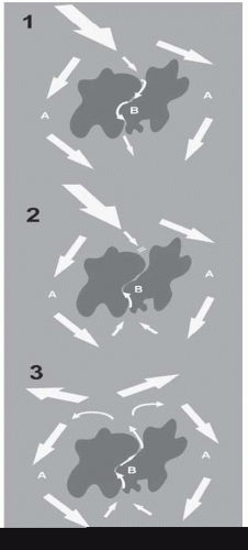
A myocardial scar acts as an area of block, around which a normal sinus wavefront passes via normal myocardium (A) and slowly through it via diseased myocardium (B)—hence there are two distinct pathways.
The sinus beat is followed closely by a ventricular ectopic, which is conducted around A normally but is blocked in B, which is still refractory following the last sinus beat.
The distal end of B, however, is now excitable and the wavefront passes backwards up B, which has had time to fully recover by the time it reaches the proximal end. Conduction is sufficiently slow up B that now A is excitable again and the wavefront can pass down A.
incremental pacing: the pacing interval is started just below the sinus interval and lowered in 10 ms steps until block occurs or a predetermined lower limit (often 300 ms) is reached
extrastimulus pacing: following a train of 8 paced beats at a fixed cycle length, a further paced beat (the extra stimulus) is introduced at a shorter coupling interval (the time between the last stimulus of the drive and the first extrastimulus). The stimuli of the drive train are conventionally termed S1, the first extra stimulus S2, the second extrastimulus S3, and so on. Extra stimuli can also be introduced after sensed heart beats (‘sensed extras’)
burst pacing: pacing at a fixed cycle length for a predetermined time.
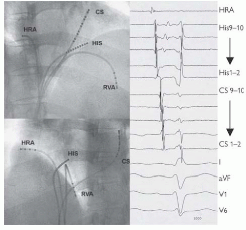
 Fig. 11.2 Standard positions of catheters in the EP study and intracardiac electrograms at those sites. Catheters have been passed up into the right heart from sheaths in the femoral veins under fluoroscopic guidance. These images from the right anterior oblique (above) and left anterior oblique (below) demonstrate the standard positions at the high right atrium (HRA) close to the SAN, on the His bundle (HIS), at the RV apex (RVA) and a catheter passed through the os of the coronary sinus (CS), which wraps around the left posterior atrioventricular groove. From this position, ICegrams are recorded from the left atrium and ventricle. This catheter is often inserted via the left or right subclavian veins. The ICegrams are conventionally ordered HRA, HIS, CS, and RV (not displayed here), with an ECG lead at the bottom. On each catheter, bipoles are then ordered proximal to distal. In SR then activation is seen to start at the HRA, pass across the His bundle, and then along the CS catheter proximally to distally. Earliest ventricular activation is at the RVA (where the Purkinje fibres insert). Normal sinus intervals are PA = 25-55 ms, AH = 50-105 ms, HV 35-55 ms, QRS <120 ms, corrected QT <440 ms men, <460 ms women. |
Table 11.2 A standard basic electrophysiology study | ||||||||||||||||||||||||||||||
|---|---|---|---|---|---|---|---|---|---|---|---|---|---|---|---|---|---|---|---|---|---|---|---|---|---|---|---|---|---|---|
| ||||||||||||||||||||||||||||||
Diagnose the mechanism of documented symptomatic tachycardia (usually proceed immediately to ablation)
Diagnose the mechanism of tachycardia in a patient with palpitations and suspected arrhythmia (may proceed immediately to ablation)
Determine electrical properties of the accessory pathway (Wolff-Parkinson-White (WPW))—stratify the risk of sudden cardiac death (SCD) and need for ablation
Risk stratification of SCD in patient with impaired left ventricular (LV) function or inherited arrhythmia, e.g. Brugada syndrome and need for implantable cardiac defibrillator (ICD)
Diagnose the mechanism of syncope—when arrhythmia is strongly suspected
Look for evidence of AV nodal conduction disease (measure HV interval) and need for pacemaker.
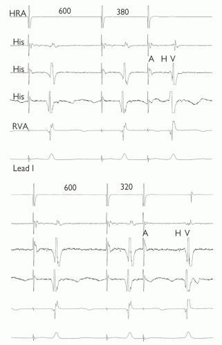
 Fig. 11.3 AV nodal jump demonstrated during anterograde conduction curve. In both panels, 5 ICegrams are shown; top to bottom: high right atrium (HRA), 3 bipolar recordings from the bundle of His (His), right ventricular apex (RVA) and lead 1 of the ECG are displayed. 8 paced beats (drive train) have been delivered through the HRA at 600 ms and then a single extra stimulus. Only the final two beats of the drive train and the extra stimulus are shown. The coupling interval of the extra stimulus is 380 ms and 320 ms in the top and bottom panels respectively. Despite only a slight shortening of the coupling interval, there is dramatic lengthening of the AH (and AV) time, suggesting dual AVN physiology. |
to aid programming of the device:
is VT well tolerated haemodynamically?
is it easily terminated with overdrive pacing?
is there VA conduction? During V pacing or VT?
are other arrhythmias present and easily induced?
From the RV apex, extrastimulus pacing, reduce the coupling interval until refractory:
1 extrastimulus during SR
2 extrastimuli during SR
1 extrastimulus following 8 paced beats at 600 ms
2 extrastimuli following 8 paced beats at 600 ms
1 extrastimulus following 8 paced beats at 400 ms
2 extrastimuli following 8 paced beats at 400 ms
3 extrastimuli during SR
2 extrastimuli following 8 paced beats at 600 ms
3 extrastimuli following 8 paced beats at 400 ms
If no ventricular arrhythmia is induced, repeat from RV outflow tract.
controlled by a computer mouse on a desktop. Sensei (Hansen Medical) is a robotic navigation system in which a steerable sheath is controlled by a robotic arm attached to the table. This responds to manipulation of a 3D joystick at a purpose-built workstation. The sheath can house any ablation catheter and therefore is compatible with any other mapping system.
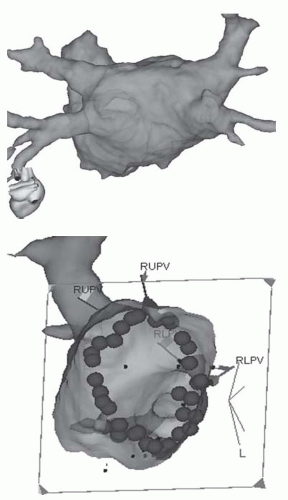
 Fig. 11.4 Image integration. The top image of a LA from the PA perspective reconstructed from an MR scan of the heart taken pre-procedure. The image is registered with the 3D mapping system. The bottom image is the LA viewed from within at a left lateral projection so that the ablation lesions that have been delivered around the right pulmonary veins are visible. |
Stay updated, free articles. Join our Telegram channel

Full access? Get Clinical Tree


