Chapter 24
Intravascular Ultrasound
Donald B. Reid, Frank R. Arko III,
Based on a chapter in the seventh edition by Katja C. Vogt and Torben V. Schroeder
Intravascular ultrasound (IVUS) is a catheter-based guidance system that is used during endovascular procedures. Whereas it was originally introduced in interventional cardiology, IVUS is now used in a wide variety of peripheral vascular interventions.1–6 The IVUS probe is passed into the vessel lumen, and because the ultrasound probe is in such proximity, great resolution of detail is possible with significant magnification. IVUS provides histologic detail of the vessel wall and also demonstrates blood flow within the lumen.7,8 It has two main clinical roles. It provides a diagnostic ability to assess and to measure the severity of disease before treatment and also demonstrates the completeness of treatment after intervention.9,10
The main limitation of catheter angiography is that it defines only the lumen and not the disease in the vessel wall.7 The increased complexity of endovascular interventions has required improved vascular imaging. Whereas computed tomographic angiography (CTA), magnetic resonance imaging, and duplex ultrasonography allow excellent imaging, these modalities have little to offer at the time of intervention. Duplex ultrasound has been used to assess the completeness of treatment after open surgical procedures and some peripheral endoluminal interventions. However, it is technician dependent and limited in thoracic, abdominal, and pelvic examinations.11–13
The first clinical use of IVUS began in the late 1980s in the coronary circulation because it provided additional information to that obtained by arteriography, namely, detailed arterial wall characteristics with a close relationship between the histologic section and the corresponding ultrasonic cross section (with regard to the location, plaque thickness, and extent of atherosclerosis along the circumference of the vessel wall).1 Arteriography provides the endovascular surgeon with details of the vessel contour, collateral circulation, quality of flow, and inflow and outflow. IVUS, however, allows greater appreciation of the vessel wall disease than only the lumen and can distinguish between soft plaque and calcification.14 Intimal flaps, thrombus formation, and ulceration are visible with IVUS, and the luminal diameter and cross-sectional areas can also be measured.15 IVUS can also detect lesions missed on conventional arteriography.9 Given that it can detect such clinically important findings, IVUS has been used to guide percutaneous transluminal angioplasty, stenting, atherectomy, laser, thrombolysis, and endoluminal grafting.4,5,10,16–21
Its clinical value within the operating room at assessing the severity of disease and subsequently the completeness of treatment was quickly appreciated. This very practical assistance within the operating room environment has become much easier to use with the developments of three-dimensional, color-flow, and virtual histology IVUS (VH IVUS). Its use is described in detail in this chapter together with the latest technical advances of IVUS and its application in different peripheral situations.
Technical Considerations
Intravascular Ultrasound Systems
There are two commercially available types of IVUS systems. The first is a mechanical system in which the ultrasound transducer is located at the tip of a flexible high-torque catheter. This allows fast rotation of the transducer. Older systems were subject to the imaging artifact of the adjacent wire. However, newer systems have a dual-purpose channel that allows catheter access over a guide wire that can then be withdrawn and replaced with the IVUS transducer. This mechanical rotation system is commercially available through Boston Scientific Corporation (Natick, Mass).
The second IVUS system type sweeps the ultrasound signal around the circumference of the probe electronically using 64 miniaturized transducer elements positioned circumferentially around the tip of the catheter. The transducers are electronically activated in sequence to produce an array of images in a plane perpendicular to the long axis of the catheter. This phased array system is currently manufactured by Volcano Corporation (Rancho Cordova, Calif).
Both types of catheters transmit sound waves covering 360 degrees of the vessel wall and create an axial image of the lumen and the vessel wall at the tip of the catheter.
Catheters and Probes
All IVUS catheters are connected to a separate console that displays the images and allows recording of still images as well as video loops. Measurements including diameter, circumference, and area can then be obtained on the workstation.
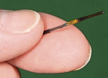
The resolution of IVUS is determined by the frequency of its beam. The higher the frequency, the greater the resolution is between two juxtaposed points of an image. When the frequency is increased, however, penetration distance is decreased because of the effects of absorption of the ultrasound beam as it propagates deeper into tissue. Thus, the appropriate catheter for a particular vessel depends on choosing the appropriate frequency for its size and depth. For example, with the Volcano system, three catheters are available: 0.014-inch and 0.018-inch catheters, which are 20 MHz, and a 0.035-inch probe at 10 MHz (Fig. 24-1). Catheters with higher frequencies between 20 and 45 MHz enable resolutions of 0.2 to 0.5 mm in the lateral direction. Frequencies between 8 and 12 MHz are best suited for the aorta, inferior vena cava (IVC), and iliac aneurysms; frequencies around 20 MHz are best suited for visualizing smaller vessels, such as occlusive iliac arteries and carotid, superficial femoral, popliteal, and tibial vessels. Higher frequencies, such as 45 MHz, are best suited for the very small diameter coronary vessels.
Lower frequency catheters, such as the 10-MHz catheter, generally require a larger 9F sheath; the higher frequency catheters can be delivered through 7F and smaller. All catheters are delivered over a guide wire. The larger catheters with lower frequency are delivered over the wire; the small catheters with higher frequencies are often on a rapid exchange system.
Another specialized catheter that is available is the Pioneer catheter (Medtronic, Minneapolis, Minn). This catheter is also on a rapid exchange system using a 0.014-inch wire. It works on a Volcano workstation and is used to gain reentry in treating aortic dissections or crossing chronic total occlusions in the subintimal space. The dual-lumen catheter integrates a phased array IVUS probe for site control and a reentry needle made of nitinol in which the depth of penetration can be controlled on the catheter. Color-flow ultrasound is used to direct the needle in the 12-o’clock position. Once reentry is obtained, a second 0.014-inch wire is then passed through the second channel into the true lumen.22
Intravascular Ultrasound Images
IVUS creates a two-dimensional gray-scale image that allows complete visualization of the three layers of the arterial wall. The intima appears as bright and echogenic, whereas the media is darker and more echolucent. The adventitia is brighter than the intima. However, the demarcation of the adventitia to the surrounding tissue is much more difficult to discern. There is a demarcation of the blood-filled lumen and the vessel wall in both arteries and veins. This allows quantification of the free luminal area and evaluation of the degree of stenosis and the distribution of plaque.
As is seen with other forms of ultrasound, calcified lesions evaluated with IVUS are bright and cause characteristic posterior shadowing. This is due to the lack of penetration of the ultrasound through calcification. In comparison, soft plaque containing lipids is more echolucent and appears darker, whereas fibrotic plaques (associated with restenosis) are brighter but without the posterior shadowing seen in heavily calcified lesions.9
Color-Flow Intravascular Ultrasound
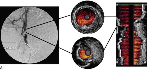
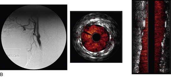
Color-flow IVUS is currently available only on the Volcano system. ChromaFlo is the computer software that detects blood flow and colors it red.8,23,24 The software detects differences between adjacent IVUS frames. As the blood cells move through the artery, they move through the IVUS image frames. The software detects differences between adjacent frames where there has been movement of blood and colors this red. ChromaFlo also detects faster flowing blood and colors it yellow. However, at present, flow velocities cannot be measured by this technique. ChromaFlo does not use the Doppler effect.25 Color-flow IVUS has been a helpful addition because it shows clearly where the lumen meets the vessel wall (Fig. 24-2).
Three-Dimensional Intravascular Ultrasound
A longitudinal reconstruction provides an image similar to an angiogram. The longitudinal image is created by performing a “pullback” of the IVUS probe through the vessel. Computer software that automatically detects the borders of layers of the artery (intima/lumen and intima/media) or the vein (intima/lumen) facilitates reconstruction of the image. Longitudinal images are generally used in conjunction with axial IVUS images to interpret the pullback. However, whereas axial images allow accurate diameter measurements, a longitudinal reconstruction is not anatomic. In tortuous vessels, the catheter tip is not always in the center of the lumen. This causes distortion as the reconstruction assumes that the catheter follows a straight path. Length measurements with the longitudinal reconstruction are therefore not accurate.26
Virtual Histology Intravascular Ultrasound
Conventional gray-scale IVUS images are created by use of the intensity (amplitude) of the returning signal. The vessel wall is either brightly reflective (echogenic, white), dark (echolucent), or in between (gray).8
VH IVUS creates an image using the frequency as well as the amplitude of the returning signal: different tissues reflect ultrasound at different frequencies.27,28 Meticulous correlation of IVUS frequency data from diseased coronary arteries with subsequent tissue histopathologic sections of the explanted vessels has enabled virtual histology data to be classified into four histologic components: fibrous, fibrofatty, calcified, and necrotic lipid core.29,30 A color-coded map of atherosclerotic plaque is produced by the VH IVUS software: dark green, fibrous; yellow/green, fibrofatty; white, calcified; and red, necrotic lipid core plaque (Fig. 24-3).
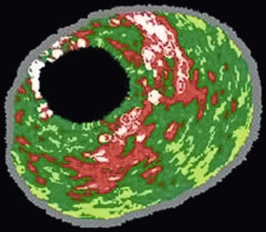
Figure 24-3 Virtual histology IVUS produces a color-coded map of the histologic components of the plaque. Dark green, fibrous; yellow/green, fibrofatty; white, calcified; red, necrotic.
VH IVUS is available only on the Volcano system and with the Eagle Eye catheter (Volcano Corporation). This catheter requires a 0.014-inch guide wire. Therefore, it is possible to use virtual histology only in relatively small vessels, such as the carotid, renal, and superficial femoral arteries. After a pullback of the probe through an arterial stenosis, an assessment of the plaque type can be made.31,32
The diagnostic accuracy of VH IVUS to correctly identify plaque types in peripheral vascular disease was investigated and validated in the Carotid Artery Plaque Virtual Histology Evaluation (CAPITAL) study, in which VH IVUS interpretation was compared with the true histopathology of carotid plaque.33 In a Food and Drug Administration–approved study and with institutional review board ethical approval, patients undergoing carotid endarterectomy had an antegrade puncture of the common carotid artery after surgical exposure of the carotid artery bifurcation. An access sheath was placed and VH IVUS was performed with use of a cerebral protection filter device. Carotid endarterectomy was then completed and the endarterectomy specimen sent for histopathologic examination. In this double-blinded study, 153 VH IVUS images were compared with the true histopathology sections from the endarterectomy specimens. The predictive accuracy of VH IVUS to agree with true histology in the different carotid plaque types was 99.4% for thin-cap fibroatheroma, 96.1% for calcified thin-cap fibroatheroma, 85.9% for fibroatheroma, 85.5% for fibrocalcific, 83.4% for pathologic intimal thickening, and 72.4% for calcified fibroatheroma. This study found that VH IVUS accurately diagnoses the different carotid artery plaque types. It was most accurate in “vulnerable plaque” types (thin-cap fibroatheroma and calcified thin-cap fibroatheroma (Fig. 24-4).
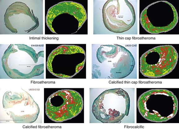
Figure 24-4 The six plaque types with examples of true histologic sections compared with the corresponding images of virtual histology IVUS that was performed immediately before carotid endarterectomy during the CAPITAL study. (From Diethrich EB, et al: Virtual histology intravascular ultrasound assessment of carotid artery disease: the Carotid Artery Plaque Virtual Histology Evaluation [CAPITAL] study. J Endovasc Ther 14:676-686, 2007.)
An interesting finding relating to plaque characterization in the CAPITAL study was that proportionally less necrotic core plaque was found in patients taking aspirin (this was statistically significant; P < .05). Similarly, the finding that nodules projecting into the lumen were statistically significantly associated with previous neurologic symptoms gives an indication of the clinical importance of these different morphologic characteristics of carotid plaque (Fig. 24-5).
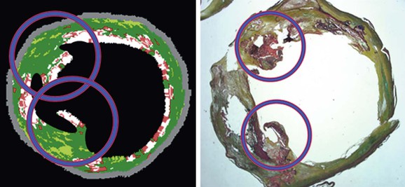
Figure 24-5 Virtual histology IVUS image and true histopathology section of carotid artery plaque show calcified projections (circled). The presence of such calcified projections was statistically associated with previous neurologic symptoms. (From Diethrich EB, et al: Virtual histology intravascular ultrasound assessment of carotid artery disease: the Carotid Artery Plaque Virtual Histology Evaluation [CAPITAL] study. J Endovasc Ther 14:676-686, 2007.)
The clinical value of VH IVUS is that with knowledge of the plaque type, the interventionalist can anticipate how the plaque is likely to behave at the moment of treatment: will it resist complete stent expansion or will it break up and embolize debris?28 VH IVUS has been used mostly in carotid artery stenting, where such information guides the way in which the patient is treated in the operating room, and it has the potential to make carotid stenting a safer procedure.34–38 However, it requires considerable experience and understanding of VH IVUS imaging and histopathology (Fig. 24-6).39–44
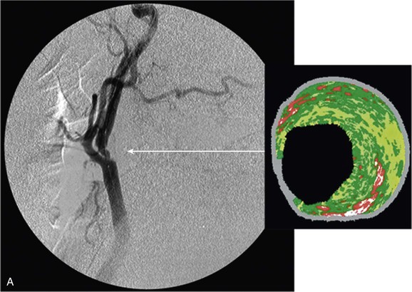
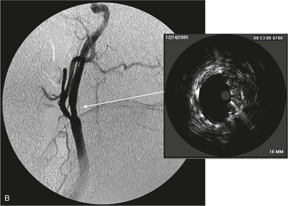
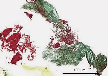
Figure 24-6 A, Angiography and IVUS demonstrate a focal stenosis at the origin of the right internal carotid artery in an asymptomatic 70-year-old man. At the narrowest point of the stenosis, the virtual histology IVUS shows predominantly fibrous (dark green) and calcified (white) areas. B, As anticipated, after stenting, there was incomplete stent expansion with midstent “waisting” despite repeated dilation at high pressures. C, Light microscopy of fibrous collagen fragments and blood clot from particles collected in the cerebral protection filter after treatment. (From Irshad K, et al: Virtual histology intravascular ultrasound in carotid interventions. J Endovasc Ther 14:198-207, 2007.)
Stay updated, free articles. Join our Telegram channel

Full access? Get Clinical Tree


