58 Intravascular Ultrasound
Intravascular ultrasound (IVUS) has evolved as the first clinical imaging method to directly visualize atherosclerosis and other pathologic conditions within the walls of blood vessels. Because the ultrasound signal is able to penetrate below the luminal surface, the entire cross-section of an artery—including the complete thickness of a plaque—can be imaged in real time. This offers the opportunity to gather diagnostic information about the process of atherosclerosis and to directly observe the effects of various interventions on the plaque and arterial wall. The first ultrasound imaging catheter system was developed by Bom and colleagues in Rotterdam in 1971 for intracardiac imaging of chambers and valves. In the early to mid-1980s, several groups began work on different catheter systems designed to image plaque and facilitate balloon angioplasty and other catheter-based interventions. The first images of human vessels were recorded by Yock and colleagues in 1988, with coronary images produced the next year by the same group and by Hodgson and colleagues.1 The intervening period has seen rapid technical improvements of the systems, with significant enhancement in image quality and miniaturization of the imaging catheters.
 Imaging Systems and Procedures
Basic Principles
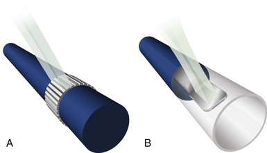
IVUS imaging systems use reflected sound waves to visualize the vessel wall in a two-dimensional, tomographic format, analogous to a histologic cross-section. These systems use significantly higher frequencies than noninvasive echocardiography, achieving greater radial resolutions at the expense of limited beam penetration. The resolution, depth of penetration, and attenuation of the acoustic pulse by tissue are dependent on the geometric and frequency properties of the transducer. Current IVUS catheters used in the coronary arteries have center frequencies ranging from 20 to 45 megahertz (MHz), providing theoretical lower limits of resolution (calculated as half the wavelength) of 31 and 19 µm, respectively. In practice, the radial resolution is at least two to five times poorer (80 to 150 µm), determined by factors such as the length of the emitted pulse and the position of the imaged structures relative to the transducer. There are two basic catheter designs, based on solid-state or mechanical approaches (Fig. 58-1). Both types of catheters generate a 360-degree, cross-sectional image plane that is perpendicular to the catheter tip.
Head-to-Head Comparisons
Mechanical systems have traditionally offered advantages in image quality compared with the solid-state systems because of the higher center frequencies and the larger effective aperture of a transducer element. Particularly, near-field resolution is excellent with mechanical catheters so that the digital subtraction of the ring-down artifact is not required. In addition, a stationary outer sheath of mechanical catheters allows the transducer to be moved through a segment of interest in a precise and controlled manner. Conversely, the longer rapid-exchange design of the solid-state catheter may track better than the short rail design of the mechanical systems in complex coronary anatomy. The distance of the transducer from the catheter tip is shorter than that of mechanical systems, which may also be beneficial in IVUS-guided intervention of chronic total occlusion (CTO) of lesions. The solid-state catheter includes no moving parts and, thus, is free from nonuniform rotational image distortion (NURD) (Fig. 58-2). This artifact can occur with mechanical systems when bending of the drive cable interferes with uniform transducer rotation, causing a wedge-shaped, smeared image to appear in one or more segments of the image. This may be corrected by straightening the catheter and motor drive assembly, lessening tension on the guiding catheter, or loosening the hemostatic valve of the Y-adapter.
Imaging Procedures
Before IVUS imaging, an intravenous injection of 5000 to 10,000 units of heparin or equivalent anticoagulation should be administered, as well as intracoronary (IC) nitroglycerine (100 to 300 mg), to reduce the risk for spasm. Mechanical catheters require a saline flush before insertion to eliminate any air in the protective sheath. Incomplete flushing can leave microbubbles adjacent to the transducer, resulting in poor image quality once the catheter is inserted (see Fig. 58-2). In either approach, image integrity should be checked before inserting the catheter. With a solid-state catheter, the catheter tip is first positioned in the aorta or a large proximal coronary vessel (not adjacent to any vessel wall) so that the ring-down artifact (a “halo” surrounding the catheter) can be electronically subtracted from the image before entering the coronary artery. If a significant ring-down artifact is observed with a mechanical catheter, microbubbles within the protective sheath may be suspected, requiring repeated saline flush procedures until the artifact is removed (see Fig. 58-2). The technique for delivering IVUS catheters is generally similar to that used for standard angioplasty or stent catheters. The imaging element is advanced distal to the area of interest, and the length of the target vessel is systemically scanned by withdrawal of the entire catheter (solid-state system) or by retracting the transducer within the protective sheath (mechanical system) over a standard 0.014-inch angioplasty guidewire. Automated pull-back devices withdraw the imaging element at a steady rate of 0.5 or 1.0 mm per second, which allows accurate axial registration of each cross-section for serial studies or precise longitudinal distance measurements.
 Safety
As with other interventional procedures, the risks of spasm, dissection, and thrombosis exist when intravascular imaging catheters are used. Early multi-center studies documented complication rates at 1% to 3%, including transient spasm as the most frequently reported event. Major complications, such as dissection, thrombosis, and abrupt closure with “certain relation” to IVUS, were identified in less than 0.5%. These studies were performed with first-generation catheters in the early 1990s, and it is likely that the incidence of spasm and other complications is substantially lower with the current generation of catheters. No acceleration in the progression of atheroma or allograft vasculopathy of arteries previously imaged by IVUS has been reported compared with noninstrumented arteries.2,3
 Image Interpretation
Three-Layered Appearance of Arterial Wall
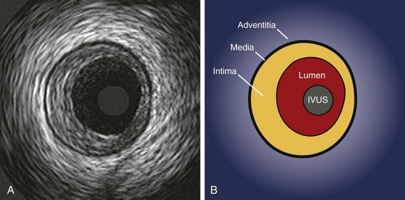
The interpretation of IVUS images relies on the fact that the layers of a diseased arterial wall can be identified separately. Particularly in muscular arteries, such as the coronary tree, the media of the vessel stands out as a dark band compared with the intima and adventitia (Fig. 58-3). Media are less distinctly seen by IVUS in elastic arteries such as the aorta and the carotid, so differentiation of the layers in those vessels can be problematic. However, most of the vessels currently treated by catheter techniques are muscular or transitional, and identification of the medial layer is usually possible (this includes the coronary, ilio-femoral, renal, and popliteal systems).
The relative echolucency of the media compared with the intima and the adventitia gives rise to a three-layered appearance (bright–dark–bright) (see Fig. 58-3). The lower ultrasound reflectance of the media is caused by the presence of less collagen and elastin than in the neighboring layers. Because the intimal layer reflects ultrasound more strongly compared with the media, a spill-over effect, known as “blooming,” is seen in the image. This results in a slight overestimation of the thickness of the intima and a corresponding underestimation of the medial thickness. Conversely, the media–adventitia border is accurately rendered because a step-up in echo reflectivity occurs at this boundary and no blooming appears. The adventitia and periadventitial tissues are similar enough in echo-reflectivity that a clear outer adventitial border cannot be defined.
Image Orientation
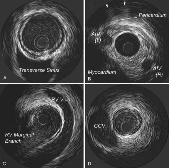
Another important aspect of image interpretation is determining the position of the imaging plane within the artery. The IVUS beam penetrates beyond the artery, providing images of perivascular structures, including the cardiac veins, the myocardium, and the pericardium. These structures have a characteristic appearance when viewed from various positions within the arterial tree, so they provide useful landmarks with regard to the position of the imaging plane (Fig. 58-4). The branching patterns of the arteries are also distinctive and help identify the position of the transducer. In the left anterior descending (LAD) coronary artery system, for example, the septal perforators usually branch at a wider angle compared with the diagonals; on the IVUS scan, the septals appear to bud away from the LAD artery much more abruptly compared with the diagonals. The combination of perivascular landmarks and branching patterns allows the experienced operator to identify the vessel and the segment from the IVUS image alone. It is also important to understand that with the current systems, the rotational orientation of an IVUS image as presented on the screen is arbitrary and can vary between imaging runs. Here again, the branching pattern and perivascular landmarks, once understood, can provide a reference to the actual orientation of the image in space. Some operators prefer to have a standard rotational orientation for each imaging run and take the time to adjust the presentation on the screen by rotating it electronically so that the branches always appear in a uniform position.
Quantitative Vessel Measurements
Unlike coronary angiograms, IVUS has an intrinsic distance calibration, which is usually displayed as a grid on the image. Electronic caliper (diameter) and tracing (area) measurements can be performed at the tightest cross-section, as well as at reference segments located proximal and distal to the lesion.4 In general, the reference segment is selected as the most normal-looking cross-section (i.e., largest lumen with smallest plaque burden) occurring within 10 mm of the lesion with no intervening major side branches. At lumen assessment, stagnant blood flow, the use of higher frequency IVUS, or both can increase the intensity of blood speckle, which may obscure the blood–tissue interface on a still image. A review of moving images can help identify the true lumen border. At procedure, saline can be injected through the guiding catheter to reduce blood speckle.
Plaque Composition on Gray-Scale Intravascular Ultrasound
The early changes of atherosclerotic disease, the so-called “fatty streaks,” are too thin to be visualized with IVUS. As plaque continues to develop, it can be resolved on IVUS, with different acoustic properties, depending on the composition of the plaque. A plaque with extensive lipid infiltration has low echo-reflectivity (less than the adventitia) on IVUS. Plaques with predominantly fibrous tissue are more echogenic than fat-laden plaques and can cause signal attenuation to some degree. Calcified plaque is recognized by a bright interface that overlies a dark shadow extending radially outward (Fig. 58-5). This acoustic shadowing, often accompanied by “reverberations” (regularly spaced arcs deep to the initial bright interface), obscures the true thickness of the calcified plaque as well as any deeper tissue. Calcium is seen by IVUS in 60% to 80% of lesions undergoing intervention, only half of which are detected by fluoroscopy or angiography. A rough rule of thumb is that an arc of calcium must occupy two quadrants (180 degrees) on IVUS to be visible on fluoroscopy. Calcium on IVUS is seen more frequently with increasing age and in patients with stable (as opposed to unstable) angina, and correlates more with plaque burden than lesion severity. One of the major limitations of IVUS in tissue identification is the difficulty in discriminating thrombus from soft plaque, which has a similar signal, or “texture,” and brightness. IVUS clues to the presence of thrombus include (1) a nodular appearance or clefts in the tissue; (2) small channels within the mass; (3) scintillating appearance (reminiscent of amyloidosis on trans-thoracic echocardiography [TTE]); or (4) tissue that moves (wiggles) in response to motion of the vessel wall.4
Advanced Tissue Characterization
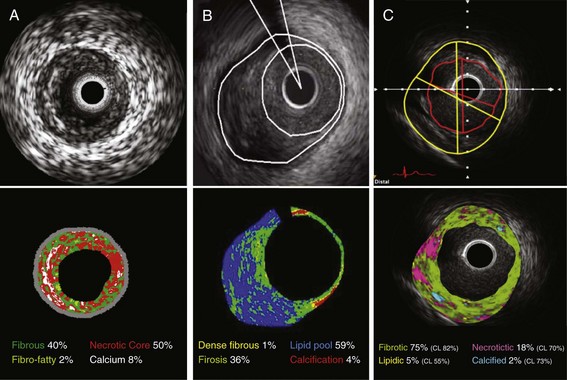
To enhance the accuracy of in vivo plaque characterization by IVUS, several advanced signal analysis techniques have been developed and introduced into the research and clinical arenas. Current commercialized systems attempt to identify tissue components directly or the deformability of the tissue (“palpography”) using computer-assisted analysis of raw radiofrequency (RF) signals in the reflected ultrasound beam.5 This analysis is based on the fact that there is greater information contained in the backscattered ultrasound signal than is revealed by the conventional amplitude-based image presentation alone. One system simply uses integrated backscatter values, calculated as the average power of the backscattered ultrasound signal from a sample tissue volume, to differentiate tissue types (IB-IVUS, YD Co., Ltd.). Two other systems employ spectral RF analyses with a classification tree algorithm developed from ex vivo coronary datasets (Virtual Histology™, Volcano Corporation) or a pattern recognition technique based on the degree of spectral similarity between the backscattered signal and a reference library of spectra from known tissue types (iMap™, Boston Scientific Corporation).6 All systems generate color-mapped images of the vessel wall, with a distinct color for each plaque component category (Fig. 58-6). When combined with automated pull-back and border detection techniques, these systems can provide a quantitative assessment of each tissue category over a three-dimensional coronary artery volume. Current technical limitations include limited spatial resolution (100 to 250 µm), no classifications for thrombus, blood, or intimal hyperplasia, and potential errors caused by poor ultrasound penetration through extensive calcification.
All systems have demonstrated a correlation of IVUS-determined plaque compositions with corresponding histopathology of coronary specimens.5
Stay updated, free articles. Join our Telegram channel

Full access? Get Clinical Tree


