45 Imaging for Intracardiac Interventions
 Introduction
Interventional cardiac procedures rely on various imaging modalities for their safety and efficacy. Traditionally, x-ray fluoroscopy and cine-angiography have been used to guide coronary angioplasty procedures, and they remain an integral part of intracardiac interventions. Fluoroscopy creates a two-dimensional view of a three-dimensional object by superimposing images. Accurate position of an object in a three-dimensional space can be determined by viewing multiple different projections or by observing motion of an object that is moving in a known direction (e.g., catheter). The major limitation of fluoroscopy is that only radiopaque objects are visible; therefore, to visualize soft tissue structures such as the myocardium, the inter-atrial and interventricular septa, and cardiac valves, radiopaque dye has to be injected. Fusion of CT images with intra-procedural three-dimensional CT and fluoroscopy can improve fluoroscopic guidance tremendously.1,2 Ultrasound-based imaging is another imaging modality that is used to guide intracardiac interventions. Both TEE and ICE depict a two-dimensional image from a two-dimensional plane. Ultrasound imaging allows visualization of soft tissue without injection of contrast material; this allows for real-time imaging during device manipulation. Although the spatial resolution of ultrasound is not as good as cine-angiography, it is adequate for visualization of most intracardiac structures. The precise location of an object in a three-dimensional space can be obtained by capturing the image of an object in multiple planes or by manipulating the ultrasound probe in a known direction. A particular limitation of ICE and TEE imaging is the difficulty of recognizing the specific aspect of a device; for instance, the tip of a catheter may appear indistinguishable from the shaft just a few millimeters proximal to the tip. However, three-dimensional TEE has helped overcome this limitation in a major way. Other limitations include restricted areas where the probe can be placed (esophagus or cardiac chambers), limiting imaging at times because of shadowing caused by metallic objects, calcium, and air. The most comprehensive approach to intracardiac imaging is the complementary use of fluoroscopy along with ultrasound imaging; this allows for combining the strengths of these imaging modalities while compensating for their weaknesses. This chapter will discuss how the structural anatomy is highlighted by using each of these imaging techniques and how imaging pearls for different intracardiac procedures are synthesized.
 Fluoroscopy
Left Ventriculogram
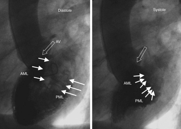
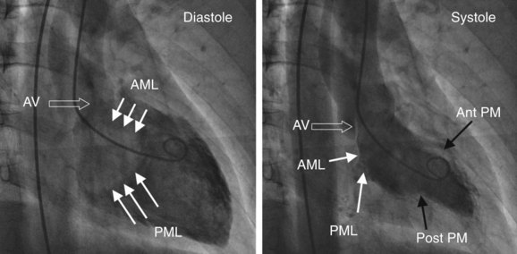
The left ventricle is typically divided into inflow and outflow segments.3 The inflow consists of the mitral valve apparatus, and the outflow portion includes the apex, the left ventricular outflow tract (LVOT), and the aortic valve. The angle between the inflow and outflow tract is around 30 degrees in young age and increases with “unfolding of the aorta.” Since the interventricular septum maintains its position while the aorta is transposed anteriorly and more horizontally, there can be “bulging” of the septum. Most commonly, this location is in the inflow portion of the left ventricular midcavity away from the septum as seen in the left anterior oblique (LAO) projection. Left ventriculogram is typically performed in the 30-degree right anterior oblique (RAO) projection; however, different views should be considered, according to the purpose of the procedure. The RAO projection delineates the separation of atria from ventricles. Various structures seen on the RAO projection are delineated in Fig. 45-1. Anterior and inferior walls and the apex are seen without overlap in this view. The lateral wall and the septum are overlapped, and their motion is perpendicular to the x-ray beam, which makes it difficult to assess them. Anterior and posterior mitral valve leaflets are seen from the side in a longitudinal plane along with the inflow portion of the ventricle. This relationship is critical and must be recognized when performing mitral valve intervention, in which devices have to be advanced coaxially in the inflow (e.g., Inouve balloon). Anterolateral and posteromedial commissures superimpose in this view; therefore, there is significant overlap between the various segments of the anterior and posterior leaflets of the mitral valve. The aortic valve and the coronary sinus can be appreciated in this view. Typically, the right coronary sinus is well separated from the posteriorly superimposed noncoronary and left sinuses. The noncoronary sinus is typically lower than the left sinus in this projection. Different structures seen on the LAO view are outlined in Fig. 45-2. To align the mitral inflow to the apex of the ventricle, some caudal angulation can be added to the LAO projection, depending on patient habitus. This allows visualization of the left ventricle in the end-on projection, where papillary muscles as well as anterior and posterior leaflets can be clearly identified. Note that the inflow and outflow of the ventricle are typically well separated in this view. (See Fig. 45-2.) The left coronary sinus is seen clearly, but the right and the noncoronary sinuses typically overlap in this projection. Unconventional views allow better delineation of certain parts of the left ventricle. The LAO cranial projection provides a better view to assess LVOT. The purpose of this projection is to visualize the anterior leaflet of the mitral valve in a longitudinal view when it does not overlap the interventricular septum. It is also the view of choice to visualize the interventricular septum in the muscular portion for the assessment of ventricular septal defect (VSD). LAO caudal projection allows the end-on view of the mitral valve. One important fluoroscopic landmark that helps “coronary interventionalists” identify mitral commissures is the coronary artery. The anterolateral commissure is located close to the division of the left main trunk (LMT) in the left anterior descending (LAD) artery and the left circumflex (LCx) artery, and the posterolateral commissure is close to the origin of the posterior descending artery.
Right Ventriculogram
The right ventricle is a trabeculated ventricle with the inflow and outflow tracts at right angles to each other. Most typically, right ventriculogram is performed in anteroposterior and lateral projections, with the catheter positioned in midcavity to prevent ventricular ectopy. The pigtail catheter or the National Institute of Health (NIH) catheter can be used to perform a right ventriculogram. The rate of injection has to be higher to identify the details (>25 cc/second). A right ventriculogram can be used to assess the pulmonary valve, the tricuspid valve, and right ventricular outflow tract (RVOT) obstruction (Fig. 45-3).
Right Atrial Angiogram
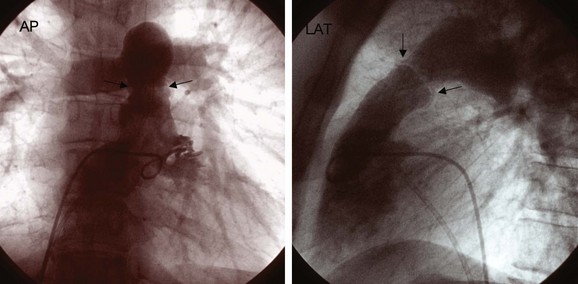
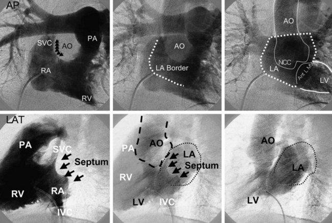
A right atrial angiogram is performed to visualize the inter-atrial septum by using the pigtail catheter or the NIH catheter with a rapid injection rate. Various anatomic structures are shown in Figure 45-4. This procedure can be used for trans-septal puncture and for the closure of patent foreman ovale (PFO) or atrial septal defect (ASD). The right atrial angiogram is performed after ASD closure to determine the relationship of the device to surrounding structures such as the aorta and left atrial walls.
Left Atrial Angiogram
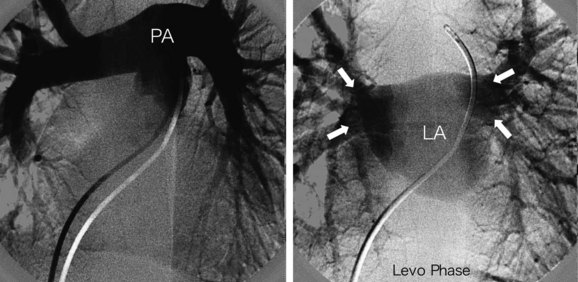
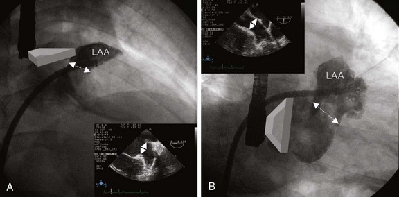
A left atrial angiogram is rarely performed by direct injection but the left atrium (LA) is frequently seen on the levo phase of the right-sided angiogram. Frequently, pulmonary artery angiogram is performed in the anteroposterior and lateral views to visualize the LA and assess pulmonary vein drainage before ASD closure (Fig. 45-5). Direct injection in the left atrial appendage (LAA) is performed to evaluate the anatomy before percutaneous closure (Fig. 45-6). The RAO cranial view shows the LAA opening in the mediolateral diameter, and the RAO caudal view delineates the superoinferior opening diameter (see Fig. 45-6). These views are also important to study the shape of the LAA, which is critical to planning percutaneous closure.
Aortogram
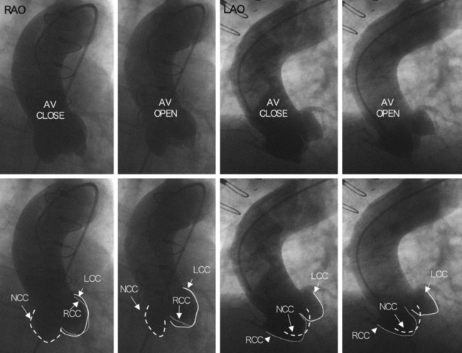
An ascending aortogram is performed to examine the aortic valve and root, aortic aneurysms, and, rarely, aortic dissections. It is performed in the RAO (30 degrees) and LAO (40 degrees) projections. High rate of injection (20 cc/second for 2–3 seconds) and proper catheter positioning allow for assessment of different aortic cusps. The aortogram is usually performed with a multi-side-hole pigtail catheter positioned just 2 to 3 cm above the sinus of Valsalva (Fig. 45-7). Various anatomic relationships must be recognized on fluoroscopy, including the relationship of the noncoronary cusp to the inter-atrial septum for trans-septal puncture, to the superior vena cava (SVC) for ICE imaging, and to the anterior leaflet of the mitral valve for antegrade interventions. These relationships are well demonstrated in a posteroanterior view on the right atrial angiogram (see Fig. 45-4).
Pulmonary Angiogram
Pulmonary angiography is the gold standard technique for diagnosing a pulmonary embolism.4 In addition, it is used to assess a variety of other conditions such as pulmonary valve stenosis, pulmonary artery stenosis, anomalous pulmonary venous return, and pulmonary arteriovenous malformation. Most commonly, multi-side-hole pigtail or NIH catheter are used with a high injection rate (40 cc/second) to visualize pulmonary veins. The dextro and levo phases of the injections are shown in Figure 45-5.
 Trans-Esophageal Echocardiography
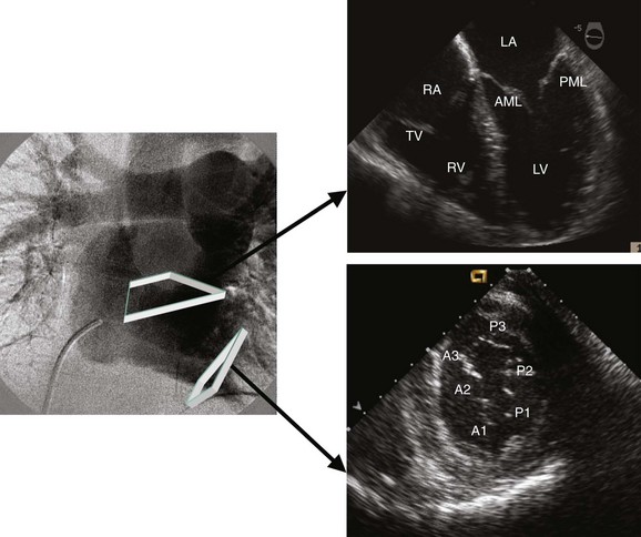
TEE has become an integral part of invasive cardiac procedures, including ASD and PFO closures, mitral valvuloplasty, aortic valvuloplasty, percutaneous aortic valve replacement, and mitral valve E-clip.5 TEE is a relatively safe procedure; however, in rare cases, esophageal tearing has been reported. Most patients in the cath lab are able to tolerate this procedure in the supine position without endotracheal intubation. Judicious use of short-acting sedatives such as midazolam and good suction of the posterior pharynx are critical for patient comfort. The TEE probe contains a 3- to 7.5-MHz (megahertz) ultrasound transducer at its tip and can be advanced to the esophagus or the stomach for proper visualization of cardiac structures.6 The tip of the probe can be anteflexed, retroflexed, or moved side to side, as needed. The currently available TEE transducers are multi-plane and consist of a single array of crystals that can be rotated from 0 degrees to 180 degrees. The common views include the 0, 40 to 60, 90, and 120 degrees. The common positions for the TEE transducer are the upper mid-esophagus, mid-esophagus, and trans-gastric positions. Three important planes can be visualized at 0 degrees from the upper esophagus to the lower esophagus (Fig. 45-8). From the upper mid-esophagus in the horizontal (0 degree) view or the basal short-axis view, the aortic arch, the pulmonary artery, the LAA, pulmonary veins, and the aortic valve can be visualized by scanning from left to right. At 0 to 20 degrees, in the mid-esophageal view or the four-chamber view, the LA, the left ventricle, the right atrium (RA), the right ventricle, the mitral valve, the tricuspid valve, and the inter-atrial septum can all be seen (see Fig. 45-8). The 0-degree trans-gastric view shows a cross-section of the left ventricle and the mitral valve (see Fig. 45-8). At 40 to 60 degrees, in the upper to mid-esophageal view, two important planes can be seen (Fig. 45-9). From the 40- to 60-degree view, the aortic valve, RVOT, the RA, the inter-atrial septum, and the LA can all be seen (see Fig. 45-9). From the 60-degree mid-esophageal level (the mitral commissural view) the mitral valve, the left ventricle, and the LA can be seen (see Fig. 45-9). In this view, the posterior mitral leaflet is to the left of the image display, and the anterior leaflet is to the right (see Fig. 45-9). Typically, A2 is located in the middle of the left ventricular inflow tract, with P1 and P3 on each side (see Fig. 45-9). At 80 to 100 degrees, with the view from the upper esophagus to the lower esophagus, three important planes can be visualized (Fig. 45-10). From the 90-degree upper-to-mid-esophageal view (the bicaval view), the SVC, the RA, the inferior vena cava (IVC), the inter-atrial septum, and the LA can all be seen (see Fig. 45-10). From the 80- to 100-degree mid-esophagus (two chamber) view, the anterior and inferior left ventricular walls, the LAA, the mitral valve, and the coronary sinus can be visualized (see Fig. 45-10). In this view, the LAA can be examined for the presence of thrombi. Similarly, in this view, P3 is to the left of the image display, and A1 is to the right (see Fig. 45-10).