LEARNING OBJECTIVES
Learning Objectives
The student will be able to describe basic chest radiographic patterns and identify normal contours created by the boundary of intrathoracic structures with aerated lung tissue.
The student will be able to recognize common abnormal radiographic patterns and be able to localize lung pathology and gather clinical information from the radiographs.
The student will be able to identify the basic anatomical unit of lung structure and how different diseases variably affect these structures on chest CT scans.
The student will be able to apply knowledge of chest x-rays and CT scans to assist in the diagnostic interpretation of clinical cases.
Imaging the chest with radiographs (x-rays) and computed tomography (CT) is an integral part of the diagnostic work-up of patients with symptoms of respiratory disease. The natural contrast of aerated pulmonary tissue provides a window into the body allowing for x-ray and CT evaluation of diseases involving the lungs, tracheobronchial tree, and pleura, as well as the thoracic lymph nodes, thoracic skeleton and chest wall, heart, esophagus, and upper abdomen. For chest x-rays in particular, it is important to understand fundamental aspects of image acquisition and the technical factors that can limit the utility of the resulting studies and interpretation of their findings. Simplistically, radiography uses ionizing x-ray radiation to generate a film image. Interactions of the x-rays with the targeted matter and the subsequent fate of x-ray photons collectively determine the generation of an image, whose characteristics will vary according to whether the radiation is completely absorbed, transmitted unchanged through the patient, or scattered within the body (Fig. 15.1).
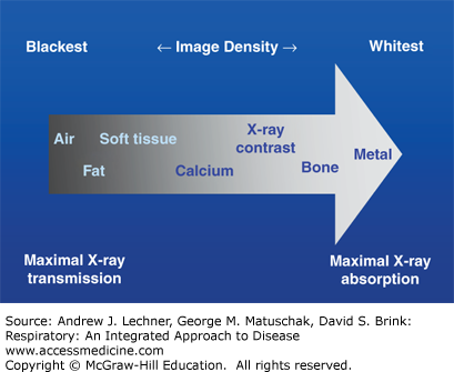
Normal anatomical features of the respiratory system, as well as pathologies of the lungs and cardiothoracic system are visualized by the interplay among seven different radiographic densities (Fig 15.1): air, fat, soft tissue (eg, muscle vs blood or fluid), calcium, x-ray contrast media, and metal (≅ dense bone). Discrimination among these features is accomplished because of differential absorption of radiation by various normal or diseased tissues that ultimately results in the creation of radiographic images. Of note, an intra-thoracic structure is best rendered visible by the juxtaposition of two different radiographic densities. Moreover, it is necessary for the x-ray beam to tangentially strike the interface between tissues of different density in order to appear as a well-defined boundary line on chest radiographs. Because diseases of the respiratory system often result in differential x-ray absorption, both the absence of a normal radiographic interface and the presence of an unexpected interface are valuable clues to underlying pathological changes.
By convention, the routine frontal chest x-ray view is taken in the radiological suite with the patient upright and during full inspiration. In this view the x-ray beam is horizontal to the patient, and the x-ray tube is ~2 m from the film detector as the beam traverses the patient from a posterior to anterior (PA) direction or view. This distance used in acquiring the PA view reduces unnecessary magnification and enhances sharpness as does the close apposition of the chest and the film. In contrast, it is frequently necessary in hospitalized and critically ill patients to obtain portable chest x-ray images at the bedside, which are performed using an anteroposterior (AP) direction or view. Such AP films involve less powerful radiation energy and a shorter x-ray tube-to-film distance, resulting in greater magnification but reduced anatomical resolution.
Using only the PA view, it is often difficult to detect chest lesions located behind the heart, near the mediastinum, or near the hemidiaphragms because these are radiographically denser structures with poor interfaces. For this reason, the lateral chest x-ray view is also performed to pinpoint such lesions three-dimensionally and localize them within the lungs. The lateral view is routinely taken with the left side of the patient against the film cassette.
INTERPRETATION OF CHEST X-RAYS
A systematic approach is essential for evaluating the normal anatomy of the lungs and thorax, and for recognizing the basic patterns of respiratory diseases. Such an approach minimizes diagnostic errors while guiding additional studies to achieve the correct diagnosis in a given patient. In reviewing chest x-ray images, it is important to simultaneously assess the quality of the study with respect to technical aspects including film exposure, since overexposure will decrease and underexposure will increase radiographic densities. Attention should also be paid to the positioning of the patient and the degree of the inspiratory effort at the instant of image capture.
The keys to successful reading of chest x-rays well are a sound understanding of normal anatomy and an orderly search pattern. The following structures are easily recognized on a PA and lateral film and should be recognized on every examination. The arrows on Figs. 15.2 and 15.3 correspond to the numbered descriptions below, respectively.
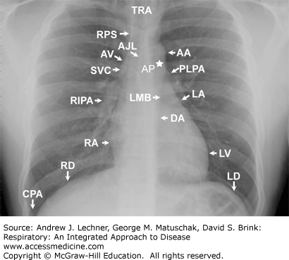
The aortic arch (AA) normally dominates the left superior cardiomediastinal contour of the patient, although it may form part of the right cardiomediastinal contour in older individuals.
The left lateral wall of the descending aorta (DA) is usually visible as it courses inferiorly through the thorax.
The proximal left pulmonary artery (PLPA) is visible in the left hilar region just inferior to the aortic arch. When visualized, the left interlobar pulmonary artery (LIPA) is noted to be inferior and lateral to PLPA.
The aorto-pulmonary window is the concavity created by the overlap of the aortic arch and the left pulmonary artery shadow.
The left mainstem bronchus (LMB) is often seen on frontal views just below the main pulmonary artery segment and the left pulmonary artery.
The appendage of the left atrium (LA) projects slightly inferior to the left mainstem bronchus and along the left cardiomediastinal contour. The left ventricle (LV) completes the rest of the left cardiomediastinal contour.
The superior vena cava (SVC) is seen in the most superior portion of the patient’s right cardiomediastinal contour.
The right paratracheal stripe (RPS) is the soft tissue stripe created by the interface of the right lateral tracheal wall and right upper lobe. Near the inferior RPS in the right tracheobronchial angle the azygos vein (AV) may be seen.
The right interlobar pulmonary artery (RIPA) exits through the right hilum inferiorly and laterally and is the predominant shadow in this region.
The right atrium (RA) forms the right cardiac border, and occasionally coursing through the cardiophrenic angle between the heart and the right diaphragm is the shadow representing the inferior vena cava (IVC).
The trachea (TRA) is usually easily seen on PA or AP (frontal) radiographs.
The right diaphragm (RD) and left diaphragm (LD) contours are clearly visible.
The costophrenic angle (CPA) is visible in the lower left portion of the thorax.
The anterior junction line (AJL) may be seen as an obliquely oriented line overlying the mediastinum representing points of contact between the two lungs.
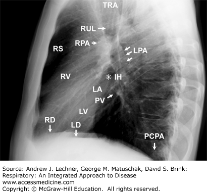
The lateral radiograph complements frontal images. Here students should focus on recognizing the normal anatomical shadowing and understand structural relationships.
The retrosternal space (RS) is the clear region anterior to, and just beneath, the sternum. This space is decreased with enlargement of the right ventricle during conditions that result in pulmonary hypertension (PHT).
The TRA is again easily visualized as in the frontal view.
The bronchial orifice of the right upper lobe (RUL) appears as a circular lucency that projects over the continuation of the tracheal air column.
The posterior wall of the bronchus intermedius is represented by the soft tissue stripe just below the orifice of the right upper lobe bronchus.
The left pulmonary artery (LPA) appears as a structure having soft tissue density that courses over the bronchus of the left upper lobe (LUL).
The right pulmonary artery (RPA) is visible as a rounded soft tissue density. It is anterior and inferior to the orifice of the RUL bronchus (#3 above).
The infrahilar window (IH, at the ✸ in Fig. 15.3) is seen just beneath the RPA; normally, this area is clear and contains only vessels and bronchi. Therefore, unexpected contouring may represent pathological adenopathy or a lung mass.
The left atrium (LA) is visible along the postero-superior aspect of the cardiac contour and just below the RPA. One or more pulmonary veins (PVs) may be seen as tubular or nodular soft tissue densities projecting over this region.
The LV forms the posteroinferior cardiac contour.
The right ventricle (RV) comprises the anterior and superior portions of the cardiac contour on lateral x-rays. The RV contour is rarely visible on AP x-rays.
One or both posterior costophrenic angles (PCPA) are visible inferiorly.
The RD and LD contours are visible inferiorly.
CLINICAL CORRELATION 15.1
Additional radiographic projections may be used in the chest x-ray evaluation of patients with diseases of the respiratory system. For example, lateral decubitus views obtained with the patients lying on their right side, left side, or both sides in sequence are helpful in distinguishing pleural effusions
Stay updated, free articles. Join our Telegram channel

Full access? Get Clinical Tree


