Integrated Imaging Modalities in the Cardiac Catheterization Laboratory


Integrated Imaging Modalities in the Cardiac Catheterization Laboratory


Robert A. Quaife

John D. Carroll


Cardiac catheterization is undergoing a major change that involves the emergence of a multitude of new therapeutic interventions.1 This revolution is the result of the development of two critical technologies and the skills to use them. The first technology includes the therapeutic devices, often accompanied by novel delivery systems, and the second technology is the medical imaging that allows the use of therapeutic devices.2 The subject of this chapter is the new cardiac catheterization imaging paradigm, which includes new imaging modalities and their integration into the cardiac catheterization laboratory. The paradigm shift can also be described by a movement to three-dimensional (3D) imaging complementing (and in the future possibly replacing) two-dimensional (2D) imaging formats.

Cardiac catheterization is intensely image guided. It is useful to first consider what this means, how image guidance initially evolved, and how the emergence of new interventions is having a profound impact on image guidance technologies. Unlike surgeons who use their eyes to directly observe cardiac and vascular structures during a traditional open heart operation, proceduralists cannot see or locate their catheters and guide where they are going without the visualization provided by medical imaging. Rather, the proceduralist views a monitor that displays a medical image. The image is an abstraction of the reality that is defined by direct observation and by specific visual skills that allow recognition of the key objects. There are many specific nuances that must be learned by the proceduralist. The early success of cardiac catheterization was made possible by the development of this unique visual skill set, the creation of catheters for diagnostic and therapeutic uses, and the development of high-quality fluoroscopy and cineangiography.


LIMITATIONS OF TRADITIONAL IMAGING SYSTEMS

Fluoroscopy is a real-time imaging modality; the proceduralist activates the x-ray system with the foot pedal and is able to immediately see the instantaneous movement of catheters, assuming they are manufactured with materials that are radiopaque. The format of the resultant image is one of the limitations of fluoroscopic imaging; the image is abstract and not inherently a complete anatomic image. This flat 2D projection is analogous to a “shadow image” but with a broader range of gray scales proportional to the variable penetration of x-rays. Years of experience and technology refinements have made fluoroscopy the workhorse modality of the cardiac catheterization laboratory.

In response to the inability to appreciate depth in the x-ray image, the cardiac catheterization imaging system was developed to allow the proceduralist to easily change the imaging perspective by altering the gantry position. Other imaging aids were developed such as road mapping using angiographic images. In addition, diagnostic and therapeutic procedures such as percutaneous coronary intervention (PCI) extensively use a system for catheter advancement called the “over-the-wire” technique. This technique is used as an alternative to the difficulty and potential danger associated with unassisted advancement of catheters in the 3D branching vascular beds both leading to the heart but also within the coronary tree.3 The over-the-wire technique converts this 3D pathway to the target into a 2D-like linear rail needed to complete the intervention using the simplicity, familiarity, and other virtues of only traditional fluoroscopy. Furthermore, relatively small amounts of contrast can be intermittently injected to visualize the small
tubular vascular structures during the final placement of therapeutic devices such as coronary stents.4,5

In prior editions of leading textbooks in cardiac catheterization the imaging material was limited to x-ray imaging and its use for diagnostic and therapeutic catheterization involving coronary and other vascular beds. The development of new interventions often targeting dynamic soft tissue and requiring new imaging modalities for navigation in large cardiac chambers has changed the educational and training needs.6 The over-the-wire technique and exclusive use of fluoroscopy, while still used, are limited by the challenges of initial navigation in open 3D space within chambers, particularly when aiming at targets such as a mitral perivalvular leak. In addition, with the evolution of PCI and other cardiac interventions it has become clear that the imaging needs to guide cardiovascular therapies are often different from the imaging needs of diagnostic procedures. It is important to understand these differences when considering and selecting new imaging modalities (Table 3.1).


EVOLUTION OF CARDIAC IMAGING IN THE CARDIAC CATHETERIZATION SUITE

The purpose of medical imaging during a therapeutic cardiac catheterization is to enable the efficient, safe, and effective performance of the sequential tasks needed for the specific intervention. The choice of imaging is dictated by the task to be performed. Each imaging modality has unique features and the same modality might have different versions.7,8 The performance of tasks as part of an intervention requires real-time imaging, of which there are only two types: fluoroscopy and ultrasound (Figure 3.1). Table 3.2 provides a comparison of these two modalities as an additional overview to understand the emergence of new approaches in the cardiac catheterization laboratory.


Table 3.1 Major Differences Between Cardiac Imaging for Dedicated Diagnostic Purposes Versus Image Guidance of Therapeutic Procedures


Dedicated Diagnostic Medical Imaging


Image Guidance of Therapeutic Procedures


Comprehensive with image sets for visualization and other derived parameters needed to assess structures and function


Focused with images to visualize equipment and targets to guide task completion and to assess immediate pre/post results and potential complications


Standardized protocols for image acquisition with predetermined list of views with minor ad hoc changes in imaging views


Flexible protocols for image guidance that are optimized ad hoc to complete specific tasks, such as optimize hand-eye coordination of interventionalist and 3D alignment of a device and target anatomy


Image acquisition and interpretation often completed separately


Real-time acquisition with immediate use and concurrent interpretation in dynamic environment


Outcome: a report with diagnostic value


Outcome: successful and uncomplicated intervention


Assessment of value of diagnostic imaging modality: evaluation using hierarchical fashion and leading to appropriateness criteria


Assessment of value of image guidance modality: evaluation more technical and incorporation in interventional guidelines (problematic)


Imaging modality use determined by diagnostic and patient considerations


Imaging modality use determined by type of intervention


Physician skill set related to modality and experience in its diagnostic use


Physician skill set related to modality and experience in both diagnostic and therapeutic guidance use


The development of interventions for the broad family of structural heart disease (SHDs) has occurred in concert with the emergence and integration of additional imaging modalities and new aspects of x-ray imaging. The nature of these new interventions is covered in other chapters. The new imaging modalities presented in this chapter are relevant to all three domains of interventional techniques, that is, coronary, vascular, and SHD.7, 8, 9

As seen with the evolution of intravascular ultrasound or intracoronary imaging, the key to the efficient use of new technology is its integration into the cardiac catheterization laboratory infrastructure.10 There are multiple levels of integration including image acquisition, processing, display, and archiving. The commercially available products that incorporate these needs for integration are rapidly evolving. All this adds the new complexity of choosing the cardiac catheterization system that provides multimodality imaging appropriate for the anticipated types of procedures that will be performed in the room.


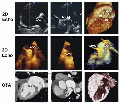
Figure 3.1 Comparison of imaging modalities characterizing the left atrial appendage structure. Biplane echocardiography is shown in the top row with the exception of the far-right image which is a surfacerendered 3D volumetric CTA display. Note the double lobes on the 3D image not appreciated on the 2 orthogonal plane echocardiographic images. The second row is 3D echocardiographic images showing the greater detail of the left atrial structure in MPR and 3D display modes. CTA 2D orthogonal views show both the internal chamber and the atrial tissue. The last image shows the threshold inversion method again giving the 3D appearance of the target structure.


Imaging Workstation and Display Systems

The imaging workstation, often with table-side controls, is one addition to the cardiac catheterization facility required by multimodality imaging.1,2 Image processing of fluoroscopic and angiographic images has become part of the internal workings of modern x-ray systems but imaging processing involving 3D volumetric image formats, segmentation, and multimodality image fusion with registration requires the imaging workstation. Direct digital links to the computed tomography angiography (CTA) and magnetic resonance angiography (MRA) hospital archival system are needed to enable the intraprocedure use of previously acquired images in patients undergoing an intervention.11

The emergence of multimodality imaging has changed the requirement standards of display systems. Monitors must
not only be able to show gray scales but also the color used to represent “depth” in 3D ultrasound images. Initially, the monitor bank was expanded with dedicated monitors for different image-based information. More recently the large single screen technology has emerged. This technology provides maximal flexibility in displaying images and other information needed during the procedure.12 The potential of displaying medical images in a holographic format is a new exciting development that may be initially tested in the cardiac catheterization environment and studied for its impact on the performance of interventions optimally performed with 3D visualization.


Table 3.2 Overview of Real-Time Imaging Modalities to Guide the Performance of Diagnostic and Interventional Tasks in The Cardiac Catheterization Laboratory


Specific variables


Fluoroscopy


Ultrasound


Field of view (FOV)


Variable and includes large field that can include whole heart and surrounding structures


Variable but upper limit of multiple cardiac chambers


System for acquisition


Limited to gantry. Either with one or two gantries (i.e., single versus biplane)


Transducer-based diversity of probes including external application to skin, transesophageal, and intracardiac


Operator


Interventionalist


Sometimes interventionalist but TEE requires echocardiographers (both physician and sonographer)


Experience with guidance of interventions


Extensive and well established over decades


Growing over last decade


Integration of technology in cardiac catheterization laboratory


Complete


Incomplete


Safety


Radiation-related risks


Probe-related risks


Strengths and weaknesses in visualization:


1) Current generation of intravascular equipment and devices


2) Navigation in vascular pathway to heart


3) Navigation in cardiac chamber


4) Navigation and interaction with soft-tissue targets such as native valves and chamber defects


5) Navigation and interaction with coronary target


6) Navigation and interaction with other vascular targets


1) Excellent


2) Excellent


3) Excellent for simple tasks but fair to good even with contrast injection for complex tasks


4) Poor and limited to intermittent contrast visualization


5) Excellent with contrast injection


6) Excellent with contrast injection


1) Limited


2) Limited to access point


3) Excellent


4) Excellent with caveat that high level of expertise required


5) Poor and nonexistent for active guidance


6) Limited


Real-time 3D visualization and create views of target/anatomy that are independent of location of image acquisition system


No


Yes


Future adaptability to robotic guidance systems and holographic display


Limited without fusion with 3D images from another modality


Yes


Development of New Skill Sets

The skill sets of the proceduralist as well as the nature of the team performing these new procedures are evolving as rapidly as the technology. Specifically, the interventional cardiologist in the past was proficient predominantly in using fluoroscopy and performing angiography. The interventional cardiologist of today and of the future must be proficient not only in these older techniques, but also in CTA, MRA, ultrasounds, and potentially Optical coherence tomography (OCT) technology, and in their use for preplanning and for the actual performance of interventions. This evolution has also led to an
expansion of the team of physicians and staff. With complex SHD interventions it has become essential that a colleague expert in ultrasound, including 3D transesophageal echocardiography (TEE), be part of the interventional team.


Value Assessment

The additional cost associated with new modalities should be evaluated against the clinical benefit and their face validity. Often the claims made by the commercial vendor are limited to technology performance rather than clinical value.13, 14, 15 The development of appropriateness criteria for diagnostic cardiovascular imaging14 has been based on determining whether the incremental information exceeds the expected negative consequences of performing the study.16 This methodology does not fit with the decisionmaking process used to determine if an imaging guidance modality is appropriate. The appropriateness of the procedure is the issue and some form(s) of image guidance is a necessity. Therefore, the value of a new imaging modality is often based on its utility and value relative to an alternative modality or as adjunctive image guidance.13 In the setting of cardiac catheterization, the comparison is typically with fluoroscopy and in other settings the comparison may be between different forms of ultrasound guidance or ultrasound versus CTA images used for fluoroscopic overlay. Examples of comparisons of different imaging guidance strategies are listed in Table 3.3.

The value of a new imaging modality for the cardiac catheterization laboratory should be determined in a fashion similar to that used for diagnostic imaging, although with a few key differences. The hierarchy of value that has been developed for diagnostic imaging includes technical aspects of imaging performance, impact on diagnostic, prognostic, and therapeutic thinking and strategies, clinical outcomes, cost effectiveness, and patient satisfaction.12 Table 3.4 summarizes factors that we believe are important in the evaluation of an image guidance modality. Technical performance is routinely evaluated. Single-center studies are sometimes conducted measuring ease of use and intermediate markers of clinical outcomes. Occasional randomized trials are conducted comparing different imaging approaches.16 Yet, new technologies are difficult to evaluate due to several factors. First, they must be studied on a procedure-specific basis to assess outcomes. Second, the number of patients studied may need to be large in order to show an impact on infrequent events such as major complications. Third, the relative contribution of the imaging modality on clinical outcomes may be difficult to differentiate from the relative contribution of other determinants, that is, the image guidance modality is part of a complex procedure where experience, patient selection, device performance, and other variables are important. Finally, the approval process for new image guidance technology by governmental regulatory agencies is often based on technical performance and general safety issues rather than on improved patient outcomes. Thus, pivotal randomized trials measuring clinical endpoints are generally not performed.


Table 3.3 Examples of Study Designs to Determine Relative Merits of Different Image Guidance Strategies


Procedure


Image Guidance Modality Comparison


Outcome Metrics


Coronary angiography


Rotational versus conventional angiography (multiple fixed gantry positions)


Radiation exposure, contrast volume, time to completion, image content


Transcatheter atrial septal defect and patent foramen ovale closure


Intracardiac echocardiography versus transesophageal echocardiography


Successful closure, complications, fluoroscopy time, procedure time, need for general anesthesia, patient satisfaction


The acquisition of new image guidance technologies for the cardiac catheterization laboratory is associated with the additional need to monitor and improve quality. The measurement of the quality of cardiovascular imaging has been modality specific and frequently has involved laboratory certification from specific professional organizations and more general hospital accreditation by government agencies.16,17 The emergence of cardiac catheterization laboratories with multimodality imaging will not only likely lead to more complex accreditation issues, but also has the opportunity to promote the development and consolidation of performance metrics and best practices for different modalities.


NEW IMAGING MODALITIES

A decade of technical advances has established the feasibility of percutaneous strategies to treat SHD such as atrial septal defect (ASD), patent foramen ovale, as well as regurgitant
or stenotic cardiac valves18, 19, 20, 21 utilizing the emergence of supportive image guidance. As more structural interventions are adopted, proceduralists are required to become adept at utilizing imaging technology that not only identifies vascular lumen or gross anatomy, but also images soft-tissue and adjacent structures. Future structural interventions hinge on the integration of imaging to navigate cardiac chambers, target different structures, and deploy a variety of therapeutic devices. Current methods such as x-ray fluoroscopy, 2D echocardiography, 3D echocardiography (3DE), cardiac MR, and cardiac CT have developed independently and merged into important adjuncts that enable the execution of complex structural interventions.8,22, 23, 24, 25 In general, there are common elements to the process of executing structural interventions; however, individual procedures emphasize particular elements. The common elements include preprocedural planning, targeting, detection/positioning and tracking, mechanical biofeedback/ eye-hand coordination, precise repositioning and alignment, navigation, 3D localization, deployment surveillance, and postprocedure inspection (Figure 3.2). These functions are discussed further in subsequent parts of the chapter and in the case-specific tasks.


Table 3.4 Assessment of Image Guidance Technology


Technological Assessment: Accuracy, image quality, reliability, graphic user interface, integration into cardiac catheterization laboratory, integration into image archiving system.


Scope of Use: General or niche applications, specific diagnostic and therapeutic procedures for which technology is appropriate (proven or expected).


Competency and Training: Relevance to board certification or hospital credentialing, learning curve, additional personnel needed with specific skill sets.


Impact on Procedure Performance: Duration, specific task performance metrics, radiation exposure, contrast volume, rate of successful procedures, rate of complications, confidence of operator during performance of procedure.


Impact on Patient Outcomes: Mortality, frequency, and outcomes of complications, successful versus unsuccessful procedures.


System, Cost, and Reimbursement: Infrastructure and other support availability for new modality, direct costs, capital costs, other infrastructural issues, personnel time.


Echocardiography

Complex cardiac interventions occur in a dynamic and anatomically intense 3D environment requiring accurate characterization of structure and function. Ultrasound image generation is dependent upon either transmission or reflection of propagated sound waves and the return frequencies characteristically produced by different tissues. The frequencies used in medical imaging are tuned to both the target tissues and the depth needing to be imaged. These ultrasound images provide the anatomic landscape for interventional procedures. However, the interaction of highly reflective devices such as a “J” wire causes reverberation or signal dropout that must be mentally integrated with tissue effects when attempting to understand the anatomic landscape.7,24,26 Conversely, some catheters or wires such as a “glidewire” demonstrate very little ultrasound signature, thus making visibility almost impossible. Understanding the ultrasound characteristic of catheters, wires, and devices and their interaction within the anatomic landscape is critical for guidance of complex interventional procedures.

Traditionally, 2D TEE and intracardiac echocardiography (ICE) have assisted such interventions.27,28 2D TEE is capable of measuring structural defects, guiding navigation of catheters, and monitoring the delivery of devices. The safety and effectiveness of 2D TEE are well established in ASD/ventricular septal defect (VSD) device sizing, equipment navigation, device deployment, and assessment of postprocedural complications such as thrombus formation.29,30 Complementary use of echocardiography with x-ray imaging results in reduced radiation exposure when ultrasound guidance for navigation is performed in combination with an effort to reduce fluoroscopy. Despite these advantages, 2D TEE still requires mental integration of multiple imaging planes on the fly when tracking objects that are often in and out of plane.31,32 This is especially true when catheters, wires, and devices are variably echogenic. In ASDs for example, defect rims are not reliably imaged within one viewing plane possibly resulting in sizing errors and increasing the risk of device embolization if the incorrect device is deployed.33 This is equally true when assessing valvular structures, and when evaluating placement of devices near coronary arteries and their relationship to the annulus of the aortic valve and planes of orientation. Imaging of near structures such as inferior vena cava or pulmonary veins may be inadequate to assess safe navigation or structure obstruction. The advantage of enhanced guidance is balanced by the risk of long interventions that require general anesthesia.7

Development of 3DE has been slow but is now universally available with most vendors marketing 3D packages, and in some cases is acquired using a single cardiac beat. Processing is much
more user-friendly compared to prior platforms.34 Real-time 3D transthoracic echocardiography (RT3D TTE) has been clinically implemented to improve endomyocardial biopsy accuracy35 and off-pump mitral valve (MV) edge-to-edge repair in a pig model.36 This was expanded to successful percutaneous ASD closure.37 The development of real-time 3D imaging with both transthoracic (3D TTE) and transesophageal echocardiography (3D TEE) integrates moving structures with definition of depth in wide field of views providing superior structure resolution. This allows definition of cardiac defects, chambers, and valves while directly and simultaneously monitoring movements of interventional devices.


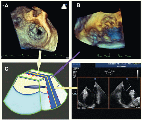
Figure 3.2 Graphic display of the volume images is shown by the three different 3D echocardiographic methods. RT3D TEE focused method is shown in panel A, which is at a focused depth that magnified 3D dataset (crème color). Shown in panel B is the narrow sector RT3D “live” method (blue color); note the larger FOV but, with less depth or thickness. Panel C, the steerable biplane technique shows the orthogonal nature of the planes (yellow lines).

Real-time 3DE obtained from the TEE probe has improved resolution of the atria, vena cava, and valves.38 The first available

RT3D TEE probe was released utilizing a matrix phase-array transducer (X7-2t, Philips, Andover, MA) that instantaneously acquires a 3D pyramidal dataset. Four different types of datasets may be acquired using this probe: complete volume gated dataset, real-time operator-focused 3D dataset, real-time zoomed 3D dataset, and simultaneous biplane adjustable 2D dataset (Figure 3.3). Volume rendering and perspective are accomplished through color shading of the volume, thereby creating a sense of depth, but precise distances are not well validated within real-time 3D acquisitions.

Complete volume data gated acquisition takes advantage of the RT3D TEE’s wide field of view (FOV) by scanning and integrating a volumetric echosector, thereby displaying
moving cardiac structures. This is a summation of four adjacent wedge-shaped volumetric datasets acquired sequentially over four cardiac cycles, with subsequent fusion into a single large echosector (Figure 3.3C).39 The dataset may be viewed offline in operator-defined cropped planes in any axis and orientation, offering several visual vantage points ideal for preprocedural planning.


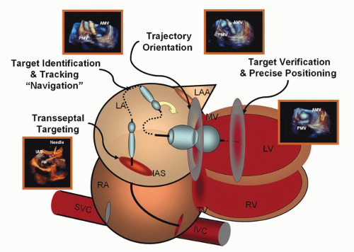
Figure 3.3 Steps for image guidance are shown. Using a mitral valve balloon valvuloplasty as an example, each key stage is shown: first, transseptal puncture; second, identification of the target; positioning and definition of trajectory; and target verification and precision adjustment. Each step is important for preplanning and procedural guidance.

Real-time 3D images may be acquired via two modes: (1) larger field of view (FOV) with focused thickness (Figure 3.3B) volume that segments heart valves, complex defects, masses, and might allow visualization of the right ventricle (RV); (2) a high magnification mode, which acquires images using an obtuse view angle and a limited sector region of interest with less depth (Figure 3.3A). The wider FOV and greater perspective are ideal for navigating catheters and interventional devices, while the thin sector 3D is better for determining edges of ASDs or leaflet insertion in valve clip procedure. Both volumetric datasets may be rotated or tilted to define desired structures and can be viewed in cropped planes of any axis and orientation. However, a systematic approach to movement of the volume is critical to avoid anatomic confusion. Thus, one could first tilt the image to gain a top view from which rotation like a clock can occur and then move toward key structures like the aortic valve positioned at 12 o’clock to provide standard perspectives such as the “surgeon’s view” of the left atrium (LA). These methods provide the advantage of online manipulation of the dataset, performed from different viewing angles or perspectives without probe repositioning or causing associated workflow interruptions.

While not a volumetric imaging mode, “X-plane” displays adjustable biplane images simultaneously. This unique feature allows operator’s definition of orthogonal specific views without movement of the probe or transducer (Figure 3.3D).39 The 2D orthogonal view method provides improved fine spatial and temporal resolution, acquired at a higher frame rate than those typically obtained employing 3D imaging. Biplane imaging also has the capability of color flow Doppler imaging that provides more precise 3D localization jets than standard 2D imaging for ASDs or regurgitant valvular lesions.

Only gold members can continue reading. Log In or Register to continue

Stay updated, free articles. Join our Telegram channel

Jun 26, 2016 | Posted by in CARDIOLOGY | Comments Off on Integrated Imaging Modalities in the Cardiac Catheterization Laboratory

Full access? Get Clinical Tree

Get Clinical Tree app for offline access