Follow-Up of the Patient who has Received a Pacemaker
Initial Pacemaker Clinic Follow-Up Visit
An organized system of follow-up is important for all device patients and is best facilitated through the patient’s membership in a formal pacemaker/ICD follow-up clinic. The first formal clinic follow-up visit is usually scheduled at approximately 3 months after implantation to allow for completion of the lead-tissue maturation process, which may affect sensing and capture thresholds. Reprogramming, to account for any threshold change since implant, and still provide a safety margin along with improved battery life, may be done at that time. Optimization of device function can be performed noninvasively. The patient generally will have additional questions at this time, and the pocket can be evaluated for appropriate healing.
Focused History and Physical
The history should focus on symptoms related to impaired cardiac output that may reflect potential pacemaker malfunction. These include palpitations, dizziness, presyncope/syncope, or any symptom that may resemble those experienced preimplantation. The possibility of pacemaker syndrome always should be considered as a potential cause for recurrent or new symptoms. Complaints related to potential pacemaker infection also should be explored, including fever, chills, recurrent respiratory illness, or reports of swelling, drainage, or tenderness in the region of the pocket. Table 11-1 lists some symptoms that should lead to the suspicion of potential problems. Fortunately, most of these problems are quite rare.
The examination consists of measuring vital signs and inspecting the pocket area. Attention should be paid to the presence of localized tenderness, swelling, or redness. The patient may complain of symptoms related to progression of his or her underlying cardiac disease so that the follow-up visit presents an opportunity for reevaluation of the patient’s general cardiac status.
TABLE 11-1 Symptoms that may alert the clinician to pacemaker problems | ||||||||||||||||||||||
|---|---|---|---|---|---|---|---|---|---|---|---|---|---|---|---|---|---|---|---|---|---|---|
|
Electrocardiogram
Twelve-lead EKG’s are no longer really required on a first visit since excellent information is obtained from interrogating the device itself. If an EKG or rhythm strip is performed, it is important to note that a unipolar spike can distort the baseline to a degree that can be mistaken for true capture. This is illustrated in Figure 11-1.
Bipolar spikes tend to be smaller than unipolar spikes (because the electricity is traveling the shorter distance through the body) and may be harder to identify. If the patient is in a clinic, a look at various leads of the electrocardiogram (ECG) may clarify the presence or absence of capture, in the case of confusing rhythm strips received over the telephone.
Fusion and pseudofusion beats are shown in Figure 11-2. A fusion beat is a QRS complex that has been formed by depolarization of the myocardium, initiated by both the pacemaker spike and the patient’s intrinsic beat. A pseudofusion beat is a QRS complex that is formed by a depolarization of the myocardium initiated by a patient’s intrinsic heartbeat completely; however, a pacemaker spike is present, distorting the QRS complex. These can be normal occurrences in pacemaker patients due to timing of the depolarization wave in the ventricle. A rarely used term is pseudopseudofusion beat. This would be an atrial spike that, by chance, lands at the beginning of a QRS complex thus mimicking a pseudo-effusion beat.
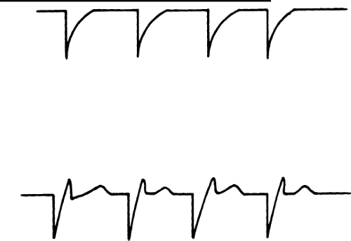 Figure 11-1 Unipolar Pacemaker Rhythm Strip. Top: A unipolar pacemaker with a large pacemaker spike and distorted baseline due to after-potential. There is no capture of the heart during this time. The distorted baseline can be mistaken for a QRS complex. Bottom: A rhythm strip in the same patient with repositioning of the lead and capture of the patient’s heart. Note the appearance of a T wave, which is often helpful in identifying true capture in this situation. |
Magnet Rate
To obtain the magnet rate, a standard magnet is applied over the pocket area for a brief period. The presence of the magnetic field causes a switch to temporarily convert the pacemaker into the VOO (asynchronous pacing) or
DOO mode in the case of a DDD device. The rate at which the pacemaker fires during the magnet application depends on the model of the pacemaker. Some models fire at a slower rate than the programmed rate, whereas others fire at the same or at a faster rate. A common question raised by clinicians concerns the safety of using the magnet mode because, theoretically, a pacing spike occurring on the T wave could induce ventricular arrhythmias. This is rarely a practical problem, however, unless significant cardiac ischemia is present. The routine use of magnet mode during transtelephonic evaluations has been shown to be generally quite safe.
DOO mode in the case of a DDD device. The rate at which the pacemaker fires during the magnet application depends on the model of the pacemaker. Some models fire at a slower rate than the programmed rate, whereas others fire at the same or at a faster rate. A common question raised by clinicians concerns the safety of using the magnet mode because, theoretically, a pacing spike occurring on the T wave could induce ventricular arrhythmias. This is rarely a practical problem, however, unless significant cardiac ischemia is present. The routine use of magnet mode during transtelephonic evaluations has been shown to be generally quite safe.
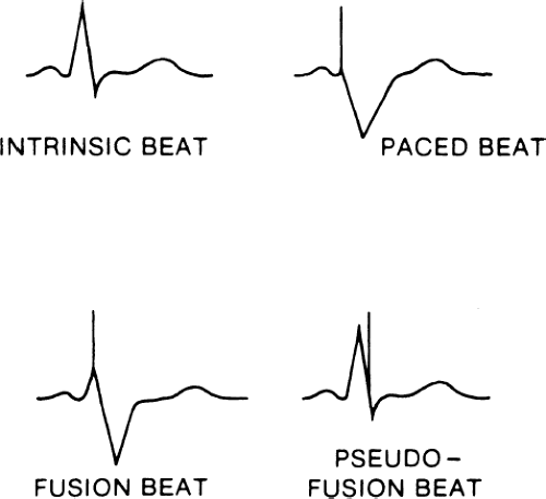 Figure 11-2 Fusion and Pseudofusion Beats. Intrinsic beats and paced beats are shown. A fusion beat is a combination of the patient’s intrinsic beat and a paced beat. A pseudofusion beat is a QRS complex caused by an intrinsic beat that is distorted by the patient’s spike, which does not obviously depolarize the myocardium. These findings are normal and do not represent pacemaker malfunction. |
Pacemaker Interrogation
The device then should be interrogated to establish the programmed parameters. The interrogation also should include evaluation of variables referred to as measured data, which include lead information (atrial and/or ventricular), such as pulse amplitude (volts), pulse width (milliseconds), current, impedance, and thresholds. Data can be printed out on paper, but a more common trend is to interact with electronic medical records and place data directly into the electronic record. This is a complex area, but a commonly used term is HL7 compatibility. This stands for Health Level 7 compatibility and involves a complex set of standards (the vast majority of which are totally unrelated to the pacing industry) for integrating hospital data into physicians’ electronic medical records.
Establishing the Underlying Rhythm
An important step is to establish the patient’s underlying rhythm and to determine whether the individual is pacemaker dependent, a condition in which hemodynamic instability would result on abrupt cessation of pacing. Because of the increased risk of serious consequences that patients may experience in the event of pacemaker malfunction, the chart should be labeled clearly in some manner (a brightly colored sticker) that the patient is pacemaker dependent.
The underlying rhythm can be uncovered by reprogramming to VVI at a low rate such as 30 to 40 bpm and recording the underlying rhythm. It is often helpful to decrease the pacemaker rate gradually to allow the native automatic focus to “warm-up.” However, an abrupt reduction in the paced rate will more accurately simulate the response to transient pacemaker malfunction.
Evaluation of Sensing Threshold
The determination of sensing threshold establishes the adequacy of the sensed amplitude of the R wave (and/or P wave). Sensitivity is a measure
of how easily the pacemaker can “see” the R wave or P wave. Sensitivity values, expressed in millivolts (mV) may be selected with the programmer and range from less than 0.5 mV to greater than 8 mV. The greatest sensitivity is associated with the smallest numeric value in mV, whereas the least sensitivity is associated with the largest mV value. Each value represents a cutoff for the ability of the pacemaker to detect the height of a given intracardiac electrogram. For example, an R wave with an amplitude of 2.4 mV will be just missed with a sensitivity setting of 2.5 mV/cm. By changing the sensitivity to 1.0 mV/cm, the generator will sense any signal with an amplitude greater than 1.0 mV and be able to track the R wave of 2.4 mV. To establish the sensing threshold, sensitivity is decreased progressively until the sensed signal is lost. The point at which that occurs is referred to as the sensing threshold.
of how easily the pacemaker can “see” the R wave or P wave. Sensitivity values, expressed in millivolts (mV) may be selected with the programmer and range from less than 0.5 mV to greater than 8 mV. The greatest sensitivity is associated with the smallest numeric value in mV, whereas the least sensitivity is associated with the largest mV value. Each value represents a cutoff for the ability of the pacemaker to detect the height of a given intracardiac electrogram. For example, an R wave with an amplitude of 2.4 mV will be just missed with a sensitivity setting of 2.5 mV/cm. By changing the sensitivity to 1.0 mV/cm, the generator will sense any signal with an amplitude greater than 1.0 mV and be able to track the R wave of 2.4 mV. To establish the sensing threshold, sensitivity is decreased progressively until the sensed signal is lost. The point at which that occurs is referred to as the sensing threshold.
Because the concept of sensitivity is difficult to grasp initially, an analogy is often helpful. Consider sensitivity value to refer to the height of a fence that blocks the view of objects (an R wave or P wave) on the other side. Although the heights of the objects are fixed, the height of the fence can be varied. By lowering the fence (from 4.0 to 0.5 mV/cm), the sensitivity is increased and the object can be brought into view (sensed); by raising the fence, the sensitivity is lowered and the signal can be shielded from view (not sensed).
In VVI (or AAI) situations, the lower rate limit of the pacemaker is programmed to a value lower than the intrinsic rate before testing is begun because you want to be able to see the native activity. If the patient’s native ventricular rate is too low, the sensing threshold test cannot be carried out. If you begin with the most sensitive level (lowest number) and progressively decrease sensitivity, threshold is reached when pacing is first observed to occur (i.e., the native rhythm is no longer “seen”).
In DDD applications, the atrial sensing threshold is tested by performing the same process: Threshold is reached when atrial pacing is first noted. To test the ventricular sensing threshold, the atrioventricular (AV) interval is lengthened to exceed the PR interval in order to allow the native QRS to be seen. The ventricular sensitivity then is progressively decreased from its most sensitive value until a ventricular pacing artifact begins to appear at the end of the expected AV interval. Because of the large R wave amplitude in most patients, R wave sensing will still occur even at the least sensitive setting, in which case the sensing threshold is recorded as being greater than this (e.g., >4.0 mV/cm). Typically, you will program in the sensitivity value that is closest to one-half the sensing threshold value.
Evaluation of Capture Threshold
Capture threshold refers to the lowest pulse-output value associated with stable capture of the myocardium and thus allows determination of the lowest safe pulse output associated with greatest battery longevity. In contrast to
sensing threshold testing, the lower rate limit of the pacemaker is reprogrammed to a value greater than the intrinsic rate before testing is begun. As in sensing threshold determination, most devices feature an automatic capture threshold test. Frequently, the pulse width is the variable that is decreased progressively until the loss of capture, although some manufacturers have automatic threshold determinations in which the pulse output is progressively decreased at a fixed pulse width. Pulse amplitude and pulse duration can be compared by noting that a doubling of pulse output will quadruple the delivered energy, in contrast to only doubling delivered energy when pulse duration is doubled.
sensing threshold testing, the lower rate limit of the pacemaker is reprogrammed to a value greater than the intrinsic rate before testing is begun. As in sensing threshold determination, most devices feature an automatic capture threshold test. Frequently, the pulse width is the variable that is decreased progressively until the loss of capture, although some manufacturers have automatic threshold determinations in which the pulse output is progressively decreased at a fixed pulse width. Pulse amplitude and pulse duration can be compared by noting that a doubling of pulse output will quadruple the delivered energy, in contrast to only doubling delivered energy when pulse duration is doubled.
In VVI applications, the ventricular capture threshold can be determined by progressively decreasing the pulse output in the graded settings or by progressively decreasing the pulse width until loss of capture. In DDD applications, the method of capture threshold testing depends on the state of underlying AV conduction. With intact AV nodal conduction, the atrial capture threshold test is carried out as follows: The device is programmed to the DDD mode with a lower rate limit set to about 20 bpm greater than the native sinus rate. The AV interval is prolonged if “native” conducted QRS complexes are not noted. The atrial pulse output is decreased in a stepwise manner until the loss of atrial capture occurs, which is signaled by the appearance of ventricular pacing at the programmed AV interval. The ventricular capture threshold is determined by programming the device in the same manner as for atrial capture testing but with the AV interval shortened to less than the PR interval. The ventricular pulse output then is decreased in a stepwise fashion until the loss of ventricular capture occurs. This will be manifest by the appearance of native QRS complexes.
In situations where AV conduction is impaired, such as second- or third-degree AV block, atrial and ventricular capture threshold testing is carried out in a slightly different manner. For atrial capture testing, the device is programmed to the DDD mode with the lower rate limit to 20 bpm greater than the sinus rate and with the shortest possible postventricular atrial refractory period (PVARP). The atrial output then is decreased in a stepwise manner until the observed occurrence of an irregular rhythm as a result of the occurrence of mixed AV synchronous and AV sequential pacing. Ventricular capture threshold testing is carried out by programming the device to DDD with the lower rate limit to 20 bpm greater than the native ventricular rate. The ventricular pulse output is decreased in a stepwise fashion until a loss of ventricular capture and heart rate slowing are noted. For situations in which the native ventricular rate is too slow or an underlying ventricular rhythm is not evident, the emergency VVI feature that most programmers have allows for rescue pacing and allows time to reprogram the ventricular pulse output to an appropriate value.
Because of the time required to attain a stable capture threshold following implant, you should probably not attempt to decrease either the atrial or ventricular voltage output until the initial follow-up visit at 3 months. At that
time, usually the pulse output value is reprogrammed to at least twice the capture threshold value. Tables 11-2 and 11-3 summarize the steps necessary to perform both sensing and capture threshold testing.
time, usually the pulse output value is reprogrammed to at least twice the capture threshold value. Tables 11-2 and 11-3 summarize the steps necessary to perform both sensing and capture threshold testing.
TABLE 11-2 Sensing threshold testing | |||||||
|---|---|---|---|---|---|---|---|
|
Sensor Evaluation
In patients with pacemakers that have programmable rate modulation, you may need to reprogram the variable pertaining to this feature. Presently, the available sensors include activity and minute ventilation or combinations of these. The manner in which the sensor is initially set up depends on the manufacturer, so you should refer to the manual to obtain guidance. Generally, ascertain whether sinus node dysfunction is present at the time of implant, and this becomes the primary criterion for selecting this type of device. Always remember that patients who are taking medications that have negative chronotropic effects often exhibit sinus node dysfunction that may benefit from the DDDR device.
If chronotropic incompetence is suspected but is minimally present, the device can be programmed to the DDD mode at the time of implant. When the patient returns for the 3-month follow-up visit, an inquiry into tolerance of mild to modest physical activity may reveal symptoms suggesting inadequate pacemaker rate response and prompt reprogramming of the DDDR mode. Modern pacemakers generally allow a histogram demonstrating the distribution of rates over a long period of time. Obviously, if the patient has a heart
rate at the lower programmed rate, then there is strong evidence of inadequate pacemaker rate responsiveness. To verify this, it is useful to have the patient walk two flights down a stairwell and back, and then reassess the heart rate response on return to the examining room. This can be done with the rhythm strip or through telemetry. Changes in the sensor-driven upper rate limit can then be made based on clinical judgment.
rate at the lower programmed rate, then there is strong evidence of inadequate pacemaker rate responsiveness. To verify this, it is useful to have the patient walk two flights down a stairwell and back, and then reassess the heart rate response on return to the examining room. This can be done with the rhythm strip or through telemetry. Changes in the sensor-driven upper rate limit can then be made based on clinical judgment.
TABLE 11-3 Capture threshold testing | |||||||||||||
|---|---|---|---|---|---|---|---|---|---|---|---|---|---|
|
Long-Term Follow-Up
Usually, patients who are not pacemaker dependent can be scheduled for annual follow-up
visits. More frequent visits may be necessary depending on whether high-sensing or capture thresholds are observed at the initial follow-up visit or if historical and physical findings suggest a problem with the pacemaker pocket wound.
visits. More frequent visits may be necessary depending on whether high-sensing or capture thresholds are observed at the initial follow-up visit or if historical and physical findings suggest a problem with the pacemaker pocket wound.
Medicare often provides guidelines for pacemaker evaluation services. Typically a telephone check every 3 months is routine with more frequent checks in the first few months after implant (to check for lead dislodgement and early problems) and then more frequent checks years later as the battery approaches end-of-life.
More technologically complex ICD monitoring systems are becoming available that will check the patient’s ICD or pacemaker (often a biventricular pacemaker placed for cardiovascular resynchronization) by using radiofrequency waves with a device in the patient’s home (it can also be carried on trips). A receiving–transmitting unit in the patient’s home transfers data automatically from the patient’s device to a monitoring station for physician review. This checks numerous parameters and automatically sends them to a central location that will analyze the data and has the capability of sending them on to the physician’s office. Data are being gathered on the utility of these more sophisticated devices. One of the goals is to reduce the need for patient follow-up, particularly if they have to travel a long distance to clinics.
Transtelephonic Monitoring
Transtelephonic monitoring allows the pacemaker’s battery status to be monitored. Basically, the patient keeps in touch with the pacemaker clinic on a routine basis by transmitting a brief rhythm strip; the magnet is applied and then removed before the end of the transmission.
Telephone transmission of a rhythm strip is a fairly simple procedure. Transmitting systems involve ECG electrodes attached to a small box. The leads can either be put on the chest or attached to the fingertips, and the electric signals are converted into sound waves that are transmitted over the telephone. A special receiver in the pacemaker clinic, which is usually hospital based but can also be in a practitioner’s office, changes the sound signals back into standard ECG form. Because the frequency response of the telephone is extremely high, a high-quality ECG signal, comparable to a routine rhythm strip signal, can be transmitted. Figure 11-3 shows a patient using a transmitter placed against the chest. On the back of the transmitter are two ECG leads that must be in close contact with the patient’s skin. Figure 11-4 shows a patient using the fingertip electrode. If the patient has a bony chest or lacks the coordination required to hold the telephone receiver against the transmitter that is held against his or her chest, the fingertip electrodes are preferable.
Some types of telephone monitoring systems sense the presence of a pacemaker spike and place a deflection representing the spike on the ECG paper. This solves the problem of visualizing low-voltage pacemaker spikes, but it can create deflections representing a spike if a portion of the QRS complex is
inappropriately sensed as a spike. From patients with no pacemaker in place (the telephone transmission was for arrhythmia monitoring), we have received rhythm strips with false pacemaker spikes neatly placed in QRS complexes. Not all telephone transmitters are designed to measure accurately the pulse widths of pacemaker spikes from dual-chamber pacemakers.
Figure 11-5 shows an example of a typical transtelephonic recording with and without the magnet.
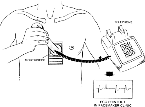 Figure 11-3 Telephone Rhythm Strip Transmitter. The patient is shown holding a battery-operated rhythm strip against his chest. On the back of the transmitter are two electrodes that are pressed firmly against the skin. These electrodes transmit an electrocardiogram, which is converted into sound waves and transmitted over the telephone mouthpiece to a receiver at the pacemaker clinic. The receiver then prints a rhythm strip. |
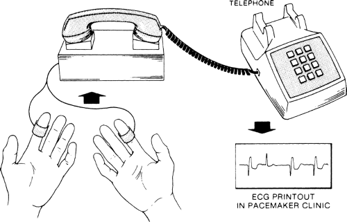 Figure 11-4 Fingertip Electrode Transmitter. Electrodes are placed on two fingers and connected to a rhythm strip transmitter. |
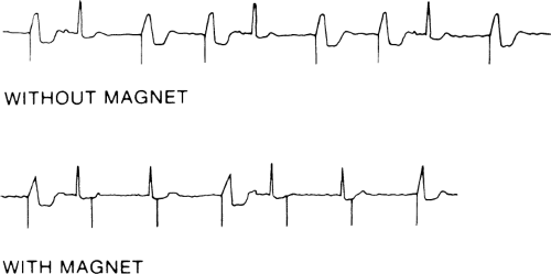 Figure 11-5 Typical Pacemaker Rhythm Strip. This could be obtained from either a telephone clinic or an outpatient clinic. Top: The patient’s rhythm without the magnet. In this example, the patient is in sinus rhythm followed by a pause, at which point the pacemaker begins to fire. Sensing is appropriate and capture is complete. Bottom: The magnet has been applied, and the pacemaker spikes march through the patient’s rhythm without sensing the patient’s intrinsic heartbeat. The second pacemaker spike does not capture because it falls within the patient’s refractory period. (Note that we are using the term refractory period in the usual electrophysiologic sense, not as it is used in pacemaker terminology.) The first and fourth pacemaker spikes fall outside the patient’s refractory period, and capture is identified. This represents normal pacemaker function. In this example, the magnet rate is the same as the paced rate, but in various models, the magnet rate may be slower or faster than the paced rate, or the magnet rate may change during the magnet cycle. |
Diagnostic Considerations for Various Electrocardiogram Abnormalities
Lack of Capture or Intermittent Capture
In the case of intermittent or complete lack of capture, sensing may or may not be present. Figure 11-6 demonstrates a pacemaker that is neither sensing nor capturing. The differential diagnosis of this problem includes the following findings:
Poor electrode position or dislodged electrode. Occasionally, the electrode will not be firmly attached to the right ventricular endocardium and may “flip up” higher on the septum or out into the atrium. Less commonly, perforation of the myocardium or accidental placement of the electrode in the coronary sinus, rather than the right ventricular apex, occurs. Another cause of this type of malfunction is an epicardial screw-in electrode that has passed through the ventricular wall into the pericardial sac and is not in good contact with the myocardium.
Poor threshold. Poor threshold may be present from the time of implantation, or a chronic rise in threshold, usually related to fibrosis around the tip of the lead, may occur. Less commonly, the patient could have a myocardial infarction involving the myocardium at the pacing tip, leading to a rise in threshold. Severe metabolic abnormalities can be a rare cause of noncapture. Cardiac medications such as antiarrhythmic drugs can affect threshold moderately but usually do not cause loss of capture unless the pacemaker is already functioning at baseline with a poor threshold.
Lead fracture. As a result of improvements in the pacemaker lead technology, lead fracture occurs infrequently.
Stay updated, free articles. Join our Telegram channel

Full access? Get Clinical Tree


