Electrophysiology Studies and Electrophysiologic Therapeutic Catheterization
J. Philip Saul
John D. Kugler
This chapter will begin by describing the indications, objectives, and techniques for performing electrophysiologic studies, intracardiac and esophageal, in the pediatric patient without congenital heart disease, and pediatric and adult patients with congenital heart disease. These groups will hereafter be referred to as pediatric and adult congenital when appropriate, where pediatric refers to neonates, infants, children, and adolescents. Following the technical aspects of performing such studies, the use of catheter techniques for arrhythmia therapy in the same group will be covered in detail.
Electrophysiologic Studies: Diagnostic
Several aspects of electrophysiologic studies in the pediatric and adult congenital patient have changed over the past two decades. This chapter will emphasize these changes while reviewing the established age-related and disease-related principles (1,2,3,4). The expanding therapeutic use of catheter ablation has had a major impact on various aspects of intracardiac electrophysiologic studies, including not only the objectives and techniques during the study, but also indications for the study. In addition to the influence of ablation, indications for electrophysiologic studies have changed because of the data from large multicenter studies involving specific arrhythmias and underlying disease processes. Although specific indications for electrophysiologic studies relative to the underlying disease, symptom, or arrhythmia are discussed primarily in other chapters, the objectives are discussed, with some emphasis on comparing intracardiac and transesophageal techniques. The advantages and limitations of each technique, as viewed in the context of age, risk/benefit, therapy, and addressing the relevant clinical questions will be discussed.
Planning the Study
The clinical questions addressed by the electrophysiologic study should be asked in advance, and the procedure should be planned and guided in this manner. The planning should include choice of intracardiac and/or transesophageal technique, needed preprocedure studies (e.g., electrocardiography [ECG], Holter monitoring, exercise testing, imaging studies); preparation or education of the patient and family; choice of sedation or general anesthesia; preparation of the patient in the procedure room or catheterization laboratory; types of equipment (catheters, sheaths); planned recording, pacing, or ablation protocols (with strategies for each); and administration of provocative or antiarrhythmic drugs. All of these issues will be addressed.
Intracardiac Technique
Educational and Emotional Preparation of Patient and Family
The importance of patient and family preparation cannot be overemphasized. The patient and family anxiety related to the potentially long duration of the study, the use of multiple catheters and protocols, and particularly the inclusion of an ablation, must be relieved which, in turn, will enhance patient cooperation. Age-related patient and family preparation begins with the pediatric electrophysiologist and is continued by pediatric cardiac/congenital heart disease electrophysiology nurses. Educational materials can be helpful at all levels.
Sedation and Anesthesia
Sedation is required for virtually all pediatric patients, and most laboratories have transitioned to using general anesthesia, or deep sedation delivered by an anesthesiologist for all electrophysiologic and nonelectrophysiologic catheter procedures. The shift toward anesthesia over sedation for any electrophysiologic study has occurred as dedicated pediatric anesthesia services have become more available, and the importance of minimizing a negative patient experience has been recognized.
Moderate sedation, in which the patient can still respond when addressed, is generally reserved for older less anxious patients undergoing just a diagnostic or transesophageal electrophysiology study.
The pain and discomfort of an ablation procedure does not appear to be significantly higher than that for a typical diagnostic catheterization, even accounting for the pain that some patients feel during the application of radiofrequency (RF) energy. Thus, general anesthesia is by no means necessary. However, many pediatric electrophysiologists began using general or near general anesthesia for most patients early in the ablation experience for two reasons. First and foremost, uncontrolled patient movement that dislodges the catheter may inadvertently occur at a critical point in the procedure, particularly if the RF application produces pain. One of the authors of this chapter (Saul), in fact experienced an isolated case of complete heart block early in his ablation experience which occurred in part from untimely movement of an uncooperative patient during ablation of a midseptal accessory pathway (AP) (5), leading to replacing deep sedation with general anesthesia for most patients. Second, most centers have found that even older cooperative children and young adults find a long procedure much more tolerable under anesthesia and are more willing to return for follow-up procedures, when needed. Currently, virtually all pediatric electrophysiologists use general anesthesia for ablation procedures.
Sedation and anesthesia agents generally are not standardized in electrophysiology laboratories, with multiple appropriate regimens used; however, there are a few common themes. In general, anticholinergic agents should be avoided because of their electrophysiologic effects. These include agents like chlorpromazine, and the drying agents atropine and glycopyrrolate. Most sedative regimens include a narcotic (e.g., meperidine, morphine, or fentanyl) for pain and benzodiazepines for sedative amnesia (e.g., diazepam or midazolam). Midazolam may be a better choice than diazepam because of its demonstrated lack of electrophysiologic effect (6,7). Antiemetics like phenergan or droperidol are acceptable, if necessary, but preferably avoided. Continuous intravenous propofol has gained increased acceptance as a deep sedative at lower doses and as a general anesthetic at higher dose (8). With propofol’s low incidence of postprocedure nausea and vomiting, patients recover faster with less lingering sedation, and because of the decreased vomiting, Valsalva-related catheter site bleeding is minimized. The electrophysiologic effects of propofol in children appear to be minimal and similar to isoflurane-based anesthetics (9).
Preparation of the Patient in Catheterization Laboratory
Initial patient preparation involves positioning and then comforting the patient on the table. When a long procedure is planned, securing the arms above the shoulders may promote the undesired complication of brachial plexus injury. Although positioning the arms inferiorly along the thorax interferes with the straight lateral fluoroscopy view, rotating slightly to 10 to 20 degrees right anterior oblique (RAO) with the anterior–posterior tubes and 80 to 70 degrees left anterior oblique (LAO) with the lateral tubes alleviates this problem while still providing acceptable views for catheter introduction. All limb and chest surface ECG leads are placed initially, allowing for a choice of displayed leads. Selection of a displayed lead is based on the underlying arrhythmia or conduction disturbance. With contemporary digital recording systems, a full 12-lead ECG is available at any time regardless of the fewer displayed leads.
Many pediatric electrophysiologists now use three-dimensional (3-D) mapping systems. Depending on the system used, the initial room setup and preparation of the patient involves steps that are required for proper function of the system (e.g., pads placed/positioned, connections and interfacing as illustrated in Fig. 21.1). Routine use of the disposable (and translucent) defibrillation pad and lead system has improved cardioversion and emergency defibrillation efficiency, and probably has improved the safety of the intracardiac study.
Sheath and Catheter Placement
In patients undergoing electrophysiologic study, special care is needed when infiltrating skin and subcutaneous areas with lidocaine (1,2,3,4). Studies have shown that therapeutic and, therefore, antiarrhythmic serum concentrations have been achieved with routine use of 2% lidocaine (10). Lidocaine can be avoided entirely in most procedures performed under general anesthesia. When used, 1.0% or less concentration can be given in sufficient amounts to achieve local anesthesia, but low enough volume to avoid a therapeutic lidocaine serum concentration.
The number, size, and location of the sheaths relate to the age and size of the patient, the underlying arrhythmia, and objectives of the study. In most studies, the number of sheaths varies between one and five, with the maximum number typically consisting of three in the femoral veins, one in the internal jugular vein, and one in the femoral artery. Sheath sizes usually correlate directly with the size of the patient and vary between 4 and 8 French (Fr). The 7- or 8-Fr sheaths are helpful when intravenous drug administration is required because a side-arm sheath larger than the catheter permits free, unobstructed flow of fluid into the vein. In addition, some ablation catheters have larger tips and require an 8-Fr sheath for introduction.
The ultimate number and location of the sheaths also depend on the success of catheter manipulation and preference of the operator. For example, the coronary sinus (CS) catheter can be advanced from the inferior vena cava (IVC) or superior vena cava (SVC). From the inferior cava approach, a catheter can be manipulated into the CS from the femoral vein/IVC by looping the catheter in the right atrium or by directly advancing it from the right atrium (2,3). If this approach is unsuccessful, a catheter can be advanced from the SVC approach, generally using a right internal jugular sheath.
A femoral artery cannula allows continuous monitoring of arterial blood pressure and may enhance safety, but its use is variable among laboratories. When a sheath is placed in the femoral artery for retrograde access to the left ventricle, a side-arm sheath one size larger than the catheter permits accurate pressure recordings. Otherwise, a small plastic cannula/dilator can be used.
The use of anticoagulation to minimize thromboembolic complications also varies among laboratories and is difficult to analyze because it is difficult to separate the diagnostic procedure from the various interventional procedures (catheter ablation and the techniques used for ablation). Although there is a variety of evidence in the literature (11,12,13,14,15), none is conclusive, and practices vary from use of heparin for all procedures to use only for interventional procedures involving pulmonary venous or systemic arterial access. When used, the heparin dose varies among laboratories, but the initial dose is usually 100 U/kg, up to a maximum 5,000 to 10,000 U, depending on the expected duration of the procedure. Ongoing anticoagulation is usually through boluses in response to the activated clotting time (ACT) measured one to two times per hour to achieve a desired value of 200 to 300 seconds for a typical left-sided SVT procedure and >300 seconds for a complex left-sided procedure, such as pulmonary vein isolation for atrial fibrillation, or when a 3-D balloon array mapping systems is used within the left atrium or ventricle.
Electrode Catheters
Diagnostic catheter sizes vary from 2 to 7 Fr. Formerly, the 4-Fr catheters were used virtually only for infants, whereas the 5-Fr catheters most often were used in young children, and 6- and 7-Fr catheters were used for adolescents and adult-sized patients. Smaller (2 to 3 Fr) catheters can be used for intracardiac recordings as well as for right coronary artery or coronary vein epicardial mapping (16). These small catheters may be used in small children to record intracardiac electrograms throughout the conduction system. Although these small catheters may be difficult to manipulate, up to three catheters can be used in the same sheath.
Catheter electrodes vary in number and interval distance. Traditionally, catheters used for recording and pacing were in a quadripolar configuration, whereas catheters used primarily for recording and mapping contain between 6 and 12 electrodes. However, currently, catheters with 6 to 20 electrodes often are used for multiple purposes, such as recording/mapping in the CS and atrial pacing. Similarly, some catheters are designed to record atrial and His potentials from proximal electrodes, while distal electrodes are used to pace the ventricle. Specially formed catheters also are available for the His location with an “S”-shaped tip providing stable seating between the anterior and septal tricuspid leaflets. These catheters tend to work best in larger pediatric patients. Short (1 to 2 mm) interelectrode distances for the bipoles, separated by 5 to 10 mm spacing allows high-quality electrograms and precise mapping, while spanning a larger region of the heart.
The number of catheters used during a study depends, not only on the size of the patient and the underlying problem, but also on whether the electrophysiologist prefers the minimum or
maximum possible amount of catheter manipulation during the study. If the least amount of catheter manipulation is desired, a greater number of catheters are positioned initially, and these are left in place for the duration of the procedure. Electrophysiologists who use more catheters prefer the advantage of simultaneous recording from the multiple catheters to optimize data collection. If multiple changes in catheter positions are deemed acceptable, fewer catheters initially are placed. Use of fewer catheters requires moving the catheter from one area to another and perhaps back to the original position during the study. However, it may not be possible without using specialized 3-D mapping systems (described later and shown in Fig. 21.5) to return the catheter to the precise original location. Electrogram consistency may also be compromised or the arrhythmia affected by the catheter movement (e.g., arrhythmia may not be inducible thereafter, so optimal gathering and recording of information is lost).
maximum possible amount of catheter manipulation during the study. If the least amount of catheter manipulation is desired, a greater number of catheters are positioned initially, and these are left in place for the duration of the procedure. Electrophysiologists who use more catheters prefer the advantage of simultaneous recording from the multiple catheters to optimize data collection. If multiple changes in catheter positions are deemed acceptable, fewer catheters initially are placed. Use of fewer catheters requires moving the catheter from one area to another and perhaps back to the original position during the study. However, it may not be possible without using specialized 3-D mapping systems (described later and shown in Fig. 21.5) to return the catheter to the precise original location. Electrogram consistency may also be compromised or the arrhythmia affected by the catheter movement (e.g., arrhythmia may not be inducible thereafter, so optimal gathering and recording of information is lost).
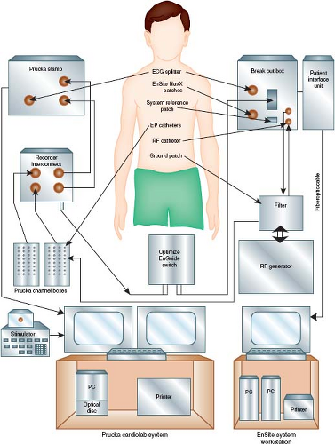 Figure 21.1 Diagram showing the major components of an electrophysiology (EP) cardiac laboratory (lab). An EP lab can be configured using equipment from several companies. In this illustration, the Prucka CardioLab System (GE Healthcare) is interfaced with the electronic stimulator. Together, they provide the system by which conventional electrogram recordings are displayed, and pacing protocols are performed and recorded. A 3-D mapping system can interface with the conventional system to enhance mapping (see text) and minimize use of fluoroscopy. In this example, the EnSite NavX (St. Jude Medical, St. Paul, MN) provides the ability to view nonfluoroscopic images of the catheter positions at the EnSite Workstation also with simultaneous conventional electrogram recordings. As shown in Figure 21.15, much greater detailed 3-D mapping images can be generated using the intracardiac balloon/electrode array EnSite system. Integration of preprocedure cardiac magnetic resonance images or computed tomographic images can be downloaded and interfaced into the 3-D recording system. |
Manipulation and placement of electrode catheters involves several factors, including patient size and age, underlying arrhythmia, objectives of the individual study, size and type of catheters (e.g., steerable), and underlying cardiac and blood vessel anatomy.
Catheter access to the left atrium or ventricle is desirable for several reasons, usually for the purpose of recording and stimulation of the left atrium and ventricle for evaluation and mapping of supraventricular tachyarrhythmias. With increasing use of catheter ablation, left-sided APs or ectopic arrhythmia foci require catheter access to the left side. The location of the CS provides precise mapping of APs along the mitral valve annulus. For left-sided atrial and ventricular ectopic foci and for ablation catheter manipulation, a lone catheter within the CS is insufficient. This has prompted use of the retrograde arterial approach or the transseptal approach via a patent foramen ovale or a transseptal needle and sheath (Brockenbrough) technique. Limitations are associated with each technique (2).
Biplane (rather than single-plane) fluoroscopy is not essential but becomes more critical as the procedure becomes more complicated. It helps minimize the risk of perforation and enhances procedural efficiency, while maximizing the precision of catheter manipulation during mapping. For mapping, especially when it involves the tricuspid annulus, mitral annulus, and posterior septal area, the positioning of the fluoroscopy x-ray tubes in a perpendicular alignment to the long and short cardiac axes optimizes recognition of anatomic relationships (Fig. 21.2). This involves rotation of the anterior–posterior tubes to approximately 30 degrees RAO position, and the lateral tube perpendicular at about 60 degrees LAO position. In addition, 10 to 15 degrees of caudal angulation of the LAO tube provides a view directly orthogonal to the mitral annulus, facilitating mapping of left-sided APs (Fig. 21.3).
Recording and Stimulation Technique
The display and recording of the intracardiac electrograms are undertaken after catheter placement. Most electrograms are displayed and recorded in a bipolar fashion, although unipolar electrograms are obtainable easily and can be helpful for mapping arrhythmia foci (17). A variety or recording and stimulation systems are commercially available. All contemporary laboratories use a digital
computer–based system that maximizes recording and stimulation efficiency by eliminating manual switching of catheter connections, eliminating paper recordings, providing a database/reporting system, and providing online measurements with freeze-scope capability (see Fig. 21.1). The 3-D mapping systems, used primarily when ablation is planned, incorporate the temporal and spatial (anatomic) details and therefore provide much more precise diagnostic data (see interventional section for more details) (18). Also, most 3-D systems have the capacity to capture continuous rhythms for analysis when sustained tachyarrhythmias are not inducible or when the arrhythmia is associated with intolerable hemodynamics. The 3-D mapping systems have added an important diagnostic component to electrophysiologic studies and also have provided increased safety by decreasing radiation exposure because catheter manipulation can be performed without, or by minimizing, fluoroscopy (19,20). Regardless of the specific 3-D system used, the general characteristics are: (i) accurately replicate the cardiac anatomy underlying the arrhythmia; (ii) provide a plausible representation of activation of that chamber, as linked to the specific anatomic site of data acquisition; (iii) readily capture and intelligibly display other details of physiology; and (iv) catalog the site of interventions (18).
computer–based system that maximizes recording and stimulation efficiency by eliminating manual switching of catheter connections, eliminating paper recordings, providing a database/reporting system, and providing online measurements with freeze-scope capability (see Fig. 21.1). The 3-D mapping systems, used primarily when ablation is planned, incorporate the temporal and spatial (anatomic) details and therefore provide much more precise diagnostic data (see interventional section for more details) (18). Also, most 3-D systems have the capacity to capture continuous rhythms for analysis when sustained tachyarrhythmias are not inducible or when the arrhythmia is associated with intolerable hemodynamics. The 3-D mapping systems have added an important diagnostic component to electrophysiologic studies and also have provided increased safety by decreasing radiation exposure because catheter manipulation can be performed without, or by minimizing, fluoroscopy (19,20). Regardless of the specific 3-D system used, the general characteristics are: (i) accurately replicate the cardiac anatomy underlying the arrhythmia; (ii) provide a plausible representation of activation of that chamber, as linked to the specific anatomic site of data acquisition; (iii) readily capture and intelligibly display other details of physiology; and (iv) catalog the site of interventions (18).
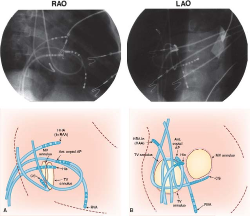 Figure 21.2 Right anterior oblique (RAO) and left anterior oblique (LAO) single-frame radiographs (top) from biplane cine with accompanying diagrammatic illustrations (bottom) showing multiple-electrode catheter positions during an intracardiac electrophysiologic study in a 6-year-old boy with Wolff–Parkinson–White syndrome (right anterior septal accessory atrioventricular pathway). A: The RAO view (anterior–posterior tubes rotated 45 degrees) provides the operator with a direct anterior–posterior view (right to left, respectively, as viewed in the radiograph and illustration), with the atrioventricular (AV) valves nearly perpendicular to the operation. B: The corresponding LAO biplane view (lateral tubes rotated 45 degrees) provides the operator with a direct left–right view (tricuspid valve annulus on left and mitral valve annulus on right, with septal area between). Note that three 6-Fr catheters were advanced from the femoral veins and positioned in the high right atrium (HRA), right atrial appendage (RAA), right ventricular apex (RVA), and His position. Two 6-Fr catheters were advanced from the right internal jugular vein and positioned in the coronary sinus (CS) posterior to the mitral valve (MV) annulus, and under the tricuspid valve (TV) leaflet anterior (ant. septal) to the His catheter where the accessory atrioventricular pathway (AP) was located. The tricuspid valve annulus and the mitral valve annulus are depicted in positions predicted by the catheter positions to demonstrate approximate locations. The surface electrocardiographic leads and skin electrodes, as well as radiofrequency and defibrillation skin pads, are not labeled. (See Fig. 21.3 for recordings from these electrode catheters in this patient.) |
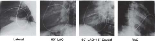 Figure 21.3 Catheter projections for ablation procedures. Note how left anterior oblique (LAO) view plus caudal angulation maximally elongates the mitral annulus. (From Saul JP, Hulse JE, De W, et al. Catheter ablation of accessory atrioventricular pathways in young patients: use of long vascular sheaths, the transseptal approach and a retrograde left posterior parallel approach. J Am Coll Cardiol. 1993;21:571–583.) |
A standard method or order of electrogram display and recording on the optical disc monitor does not exist, but typical examples are illustrated in Figure 21.4. It is advantageous to record at least
three or four simultaneous surface ECGs, including two perpendicular limb leads to elicit P or QRS frontal plane axis changes and one or two chest leads to maximize detection of bundle branch changes. A major effort should be undertaken to record a His bundle electrogram (HBE). An HBE is required for the definitive identification of the mechanisms of virtually all arrhythmias and conduction system disturbances. When the usual catheter position (superior or septal tricuspid valve annulus) fails to elicit an HBE, advancing a catheter retrogradely to the noncoronary aortic sinus can allow successful recording. Once obtained, 3-D mapping systems allow for registration of the location without necessarily maintaining a catheter in the HBE location. With catheters used for both recording and stimulation, the distal pair of electrodes is best for pacing consistency, and all proximal pairs are then used for recording. Because of fast tachycardia rates in children, fast recording capability (200 mm/s or higher) is essential to differentiate electrograms recorded by the various electrode catheters (Fig. 21.4).
three or four simultaneous surface ECGs, including two perpendicular limb leads to elicit P or QRS frontal plane axis changes and one or two chest leads to maximize detection of bundle branch changes. A major effort should be undertaken to record a His bundle electrogram (HBE). An HBE is required for the definitive identification of the mechanisms of virtually all arrhythmias and conduction system disturbances. When the usual catheter position (superior or septal tricuspid valve annulus) fails to elicit an HBE, advancing a catheter retrogradely to the noncoronary aortic sinus can allow successful recording. Once obtained, 3-D mapping systems allow for registration of the location without necessarily maintaining a catheter in the HBE location. With catheters used for both recording and stimulation, the distal pair of electrodes is best for pacing consistency, and all proximal pairs are then used for recording. Because of fast tachycardia rates in children, fast recording capability (200 mm/s or higher) is essential to differentiate electrograms recorded by the various electrode catheters (Fig. 21.4).
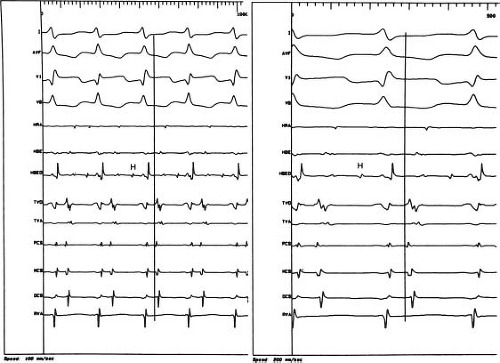 Figure 21.4 Two recordings in a 3-year-old boy with incessant, fast (220-ms cycle length; rate 272 beats per minute), orthodromic reciprocating atrioventricular (AV) reentrant supraventricular tachycardia that demonstrate the advantage of fast recording speed. Left: Using a recording speed of 100 mm/s, the earliest retrograde (conduction via posterior septal accessory AV pathway) atrial activation was difficult to determine. The atrial activation closest to the vertical line appeared to be either from the distal pair of electrodes on the tricuspid valve annulus mapping catheter (TVD) located at the posterior septal area, or from the proximal pair of electrodes on the coronary sinus (PCS) catheter, located approximately 0.5 cm into the coronary sinus from the os. Right: By doubling the recording speed to 200 mm/s, the earliest electrogram not only appeared to be more easily detected by the TVD electrodes, but the low-amplitude earliest electrogram appeared to be from the accessory AV pathway. |
The pacing and recording protocols used are variable, and emphasis should be on flexibility and patient-specific diagnosis and findings. The specific protocols chosen should be adapted to the patient as they relate to the preprocedure diagnosis, but they also should remain flexible during the study, dependent on ongoing elicited findings. It is beyond the scope of this chapter to provide examples of protocols for each specific type of arrhythmias and conduction disturbances. Most can be found either elsewhere in this chapter or in the literature (2,3,21,22,23). However, in Table 21.1, a list of pacing protocols provides examples of options used during intracardiac studies. Also, with the advent of catheter ablation and with the advances in 3-D mapping technology, the techniques and objectives of mapping have assumed a major new role and are emphasized in the interventional section of this chapter. The important general mapping concepts include the fluoroscopic image, catheter manipulation techniques, various modes of pacing, nuances of electrogram recordings, and 3-D mapping.
Administration of Drugs
Intravenous drug administration during an intracardiac study encompasses three general categories: anesthetic drugs, provocative arrhythmic drugs, and antiarrhythmic drugs. Of the three, anesthetic drugs are the most commonly administered and were discussed earlier in this chapter. The most commonly used provocative arrhythmic drug is isoproterenol. Other less frequently used provocative drugs include epinephrine, atropine, aminophylline, phenylephrine, procainamide, or flecainide (for Brugada syndrome) (2,3,24,25,26). Because of sleep- or sedative-induced vagotonia, these provocative drugs may be necessary to induce or sustain tachycardia, which is essential to determine arrhythmia mechanisms and the site of arrhythmia foci or pathways. Also, some arrhythmias can be observed only when the heart rate is lower, or are observed better in the presence of second-degree AV block (e.g., atrial reentry tachycardia), both situations where enhanced vagotonia is helpful and can be induced by an infusion of phenylephrine titrated to moderately raise arterial pressure. The doses of isoproterenol and epinephrine continuous-drip infusions are similar and range from 0.01 to 0.1 μg/kg/min. Atropine (0.01 to 0.04 mg/kg) is used infrequently because it cannot be administered as a continuous infusion and because of its longer-lasting effects. Phenylephrine can be given as a bolus of 0.50 to 1.0 μg/kg and titrated as an infusion to the desired blood pressure.
Before the ablation era, antiarrhythmic drug administration during intracardiac electrophysiologic study was used commonly to assess drug safety and efficiency of planned chronic therapy. Although chronic medical therapy still exists as a treatment option (especially for patients with ventricular arrhythmias), its use is declining because of the increased application of ablation treatment and cardioverter-defibrillator device options.
Antiarrhythmic drug administration is also used commonly to achieve acute effects. This is indicated most often in an attempt to block atrioventricular (AV) nodal conduction. The AV nodal blocking effects of verapamil, esmolol, propranolol, adenosine, or phenylephrine (as discussed above) are helpful to elucidate arrhythmia mechanisms and to distinguish the type of AV and ventriculoatrial (VA) conduction, if present (27,28,29,30).
Complications
Complications have been reported and analyzed for nonelectrophysiologic cardiac catheterizations in children (31,32,33,34,35,36). Only the 1998 report by Vitiello et al. (35) and the summary in a previous edition of this book by Kugler (37) have separate analyses of electrophysiologic studies. In Vitiello et al. extensive statistical analysis diagnostic electrophysiologic procedures had the lowest rate of major complications at 0.7%, similar to the 0.8% of other diagnostic procedures, and both were less than the interventional (ablations included in interventional) rate of 2.0%. An electrophysiologic study was not an independent risk factor for a complication. However, because ablation was included as an interventional procedure, it was an independent risk factor for complication during electrophysiologic study. It appears that addition of an ablation procedure increases the risk of the procedure to a level similar to that of other interventional catheter procedures (37). For the Pediatric Electrophysiology Society’s catheter ablation registry, Schaffer et al. (38) studied the mortality rate and found a mortality rate of 0.12% for all ablation procedures. For those with underlying structural heart disease this was increased to 0.89%. Mortality was also higher in those requiring a greater number of energy applications, left-sided procedures, and those with a lower body weight. The latter risk factor also was found in the single-center report of Rhodes et al. (33) for patients ≤5 kg, but they included only nonelectrophysiology catheterization procedures.
Transesophageal Technique
This section covers both the isolated transesophageal study, as well as one performed as a preliminary study for SVT inducibility or risk stratification in the patient with Wolff–Parkinson–White (WPW) syndrome prior to a possible catheter ablation procedure. The primary difference is that sedation might be replaced by general anesthesia if an ablation is being considered to immediately follow the transesophageal procedure.
Educational and Emotional Preparation of Patient and Family
The preparation of the patient and family for a transesophageal study centers on explaining the technique and addressing expectations and concerns related to placement of the catheter followed by pacing and stimulation. Educational materials backed by an honest but positive and confident approach during the explanation session are important in successfully achieving the goals of a transesophageal study in an older child or adolescent. In infants and small children, the same approach is modified and directed toward the parents.
Sedation
If general anesthesia is not being used as described above, mild to moderate sedation usually is sufficient to maximize patient cooperation while relieving discomfort and anxiety. For infants, children, and adolescents, intravenous midazolam (0.05 to 0.1 mg/kg) with morphine (0.05 to 0.1 mg/kg) or fentanyl (1 to 2 μg/kg), is an effective analgesic/amnesic sedative combination. Before a peripheral intravenous line is established, oral diazepam (0.2 to 0.4 mg/kg)
or intranasal midazolam (0.2 to 0.3 mg/kg) can also be used to control anxiety and thereby allowing the patient to be more cooperative (39).
or intranasal midazolam (0.2 to 0.3 mg/kg) can also be used to control anxiety and thereby allowing the patient to be more cooperative (39).
TABLE 21.1 Pacing Protocols for Intracardiac Electrophysiologic Study | ||
|---|---|---|
|
Preparation of Patient in the Procedure Room
Whether in an inpatient or outpatient setting, the transesophageal technique is adaptable to virtually any type of room or location where the patient can be comfortably supine and where sufficient space exists for equipment and monitoring. After peripheral intravenous access is established, the surface ECG leads are placed and connected. A direct current (DC) defibrillation and cardioversion system should be available, or chest pads can be placed routinely, as with most intracardiac studies. Sedation is administered as needed with appropriate vital sign (heart rate, respiratory rate, and blood pressure) and oximetry monitoring protocols established. In most infants and children, comfortable extremity restraints are necessary to prevent withdrawal of the catheter by the patient. The success of a transesophageal study depends highly on a positive,
encouraging approach during the procedure by the pediatric electrophysiologist, pediatric cardiology nurse, and associated personnel. A soothing, comforting manner is necessary for successful passage of the catheter, as well as for successful recording and stimulation because of the potential mild discomfort encountered during each of these steps.
encouraging approach during the procedure by the pediatric electrophysiologist, pediatric cardiology nurse, and associated personnel. A soothing, comforting manner is necessary for successful passage of the catheter, as well as for successful recording and stimulation because of the potential mild discomfort encountered during each of these steps.
Catheter Placement
Similar to passage of a nasogastric tube, initial placement of the catheter involves lubrication (KY type jelly usually is sufficient, but local lidocaine gel can be beneficial). Entry through the nares is followed by firm but gentle advancement through the posterior pharynx into the esophagus. Encouragement of repeated swallowing by the awake patient facilitates the catheter placement. The distance of catheter advancement required to reach the predicted area best suited for recording and pacing directly correlates with patient height (40) (Fig. 21.5). However, this predicted depth may not actually be the ideal location, and minor adjustments may be necessary. The optimal catheter electrode position for pacing correlates with the highest atrial electrogram amplitude. Short distances (a few millimeters) of catheter withdrawal and advancement are performed until the maximum atrial electrogram amplitude is found. The catheter is then secured by taping it to the patient’s face or nose.
Equipment and Recording/Stimulation Technique
The three major equipment components are the electrode catheter, the recording apparatus (monitor, strip-chart recorder), and the stimulator (Fig. 21.6). Successful transesophageal recording and stimulation in infants, children, and adolescents have been reported with various types of electrode catheters. Transesophageal electrode catheters differ in size (4 to 10 Fr), interelectrode distance (2 to 30 mm), and number of electrodes (bipolar, quadripolar, hexapolar). Although the adult “pill” electrode can be used in the older child and adolescent, the electrode catheter is better suited for the pediatric patient. Moreover, some transesophageal catheter manufacturers have been receptive to customized catheter design regarding electrode number and interelectrode distance. Interelectrode distance (12, 22, and 28 mm) was found to have no significant effect on pacing thresholds regardless of age or size of the patient (32,36,40,41). Essentially no data are available that compare catheter sizes in pediatric patients; however, intuitively, if electrode contact with the esophageal wall is an important goal, the largest possible catheter size should be used. In normal-sized newborn infants, the nares easily accommodate catheters in the 5 to 7 Fr range; however, a 10-Fr catheter can be placed through the mouth if there is difficulty with the smaller catheter in the nares. In older children and adult-sized adolescents, 10-Fr catheters are used most often. Bipolar electrode configuration limits the technique to either recording or pacing and so quadripolar electrode catheters have been designed to permit simultaneous pacing and recording, with the recording interelectrode distance shorter (2 mm) than the pacing interelectrode distance (12 to 30 mm). Nonetheless, most catheters used today are bipolar.
The recording equipment consists minimally of a strip-chart recorder with an ECG monitor. Without a monitor, the strip-chart recorder can run continuously and, therefore, also functions as the monitor. The recording system can be set up in a unipolar or bipolar fashion (Fig. 21.7). When possible, performing the procedure in the intracardiac EP laboratory allows for use of the same digital recording system used for more complex studies, with all its inherent advantages and standard signal filtering capabilities.
A unipolar recording system is the simplest and involves the lowest investment in equipment because a preamplifier is not required. A three-channel ECG machine can function as both a strip-chart recorder and monitor (Fig. 21.7). One channel can be used for a unipolar esophageal lead and the other two channels for two surface ECG leads. For example, the V1 chest lead can be connected to one of the electrodes on the transesophageal catheter. The recordings from the V2 and V3 chest leads are then displayed or recorded simultaneously to permit comparison of the QRS and
P waves on the surface leads with the electrograms from the unipolar esophageal lead (Fig. 21.8). Alternatively, two simultaneous unipolar esophageal electrograms, each from a separate esophageal electrode, can be displayed or recorded with the recording from one surface ECG lead. Recording during pacing is carried out either without the simultaneous transesophageal electrogram, by reconnecting the V1 chest lead to the V1 skin lead as illustrated in Figure 21.9, or with the simultaneous recording from a transesophageal lead (Fig. 21.10).
P waves on the surface leads with the electrograms from the unipolar esophageal lead (Fig. 21.8). Alternatively, two simultaneous unipolar esophageal electrograms, each from a separate esophageal electrode, can be displayed or recorded with the recording from one surface ECG lead. Recording during pacing is carried out either without the simultaneous transesophageal electrogram, by reconnecting the V1 chest lead to the V1 skin lead as illustrated in Figure 21.9, or with the simultaneous recording from a transesophageal lead (Fig. 21.10).
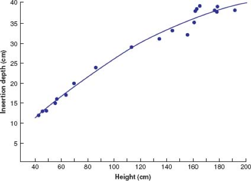 Figure 21.5 Graph of depth of transesophageal electrode catheter insertion (measured from distal electrode on catheter) from the nares in pediatric patients of various heights. By plotting the patient’s height, in centimeters, the correlating distal electrode depth can be determined. After the distal electrode has been positioned at the predicted depth, small adjustments may be necessary for optimal recording and pacing. (From Benson DW Jr, Sanford M, Dunnigan A, et al. Transesophageal atrial pacing threshold: Role of interelectrode spacing, pulse width and catheter insertion depth. Am J Cardiol. 1984;53:1102–1106.) |
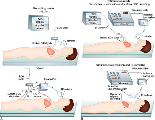 Figure 21.6 Diagrammatic illustration showing the recording and stimulation components of the transesophageal (TE) electrophysiologic technique. The recording mode (A) can be set up in a simple unipolar system (top) by connecting one esophageal electrode terminal to a surface ECG lead (e.g., V1) while recording one or two other simultaneous surface ECG leads (e.g., V2, V3). (See Figs. 21.7 and 21.10A for examples of unipolar recordings.) A bipolar recording system (bottom) can be used by adding a preamplifier. (See Fig. 21.10B for an example of a bipolar recording.) The stimulation mode (B) can be setup using either a bipolar or a quadripolar transesophageal electrode catheter. The bipolar electrode catheter permits only recording or stimulation, but not both simultaneously. An example of bipolar pacing using a bipolar electrode catheter is shown (top) with recording of the surface ECG during pacing. (See Fig. 21.8 for an example of ECG recording during tracing.) Simultaneous esophageal recording during pacing (bottom) can be accomplished in a unipolar or bipolar recording mode. (See Fig. 21.9 for an example of unipolar recording during pacing.) LA, left arm; LL, left leg; RA, right arm; RL, right leg. |
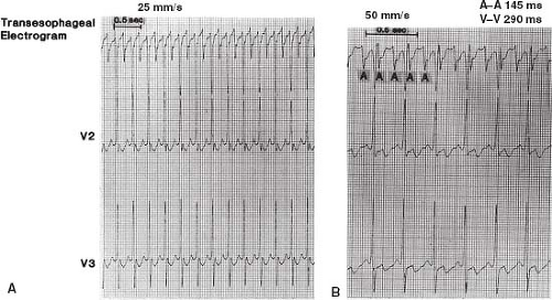 Figure 21.7 Unipolar simultaneous transesophageal recordings (top) with surface leads V2 and V3 at two recording speeds (A: 25 mm/s; B: 50 mm/s) from a newborn baby with sustained, regular tachycardia, 206 beats per minute (290-ms cycle length), showing atrial flutter (2:1 atrioventricular block) as the mechanism. The atrial (A-A) cycle length (145 ms) was half of that of the ventricular cycle length (290 ms). |
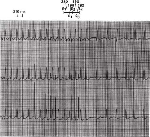 Figure 21.8 Recordings (25 mm/s) from simultaneous surface electrocardiographic leads (V1, V2, V3) in a 7-year-old boy with intraatrial reentry tachycardia (underlying cardiac diagnosis: Postoperative Fontan’s) showing conversion of the atrial tachycardia (310-ms cycle length) by transesophageal atrial pacing using a bipolar electrode catheter. After multiple modes of atrial pacing protocols, successful conversion to sinus was finally accomplished with eight beats of a 280-ms drive cycle length, followed by three extrastimuli (190-ms intervals each). |
A bipolar system has the advantages of more reproducible and reliable atrial electrograms. The baseline wanders less, and the atrial electrograms are more distinct and the ventricular electrograms less prominent, which makes the recordings more distinguishable. A bipolar system is also better than a unipolar system with regard to pacing-induced artifact, but the latter is not eliminated by a bipolar system because the high amplitudes and long pulse widths of bipolar transesophageal pacing present a problem in ECG recording and, therefore, measuring intervals.
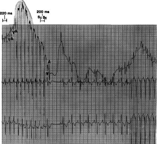 Figure 21.9 Unipolar transesophageal simultaneous recordings (top) with surface leads V2 and V3 from a 3-year-old boy with incessant normal and wide QRS supraventricular tachycardia (220-ms cycle length), showing simultaneous transesophageal pacing (interelectrode distance 24 mm) and recording (interelectrode distance 2 mm). Using a quadripolar electrode catheter, the esophageal recording (V, ventricular; A, atrial) during tachycardia was interrupted by eight beats of atrial pacing (200-ms cycle length), which converted the tachycardia to several beats of sinus before wide QRS reciprocating atrioventricular reentrant supraventricular tachycardia recurred. Note the wandering baseline of the unipolar esophageal recording before, during, and after pacing. |
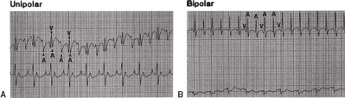 Figure 21.10 Two transesophageal recordings (50 mm/s) in a 2,250-g newborn with atrial flutter (150-ms atrial cycle length) and 2:1 atrioventricular block, showing a comparison of unipolar (A) and bipolar (B) recordings. Note that the prominent ventricular electrogram and the wandering baseline in the unipolar recording are eliminated in the bipolar recording. Therefore, the atrial electrogram is better delineated in the bipolar recording. |
The stimulator system requires capability for a long pulse width (≥10 ms) and high current (10 to 25 mA) (40,42,43). Several investigators have shown that pulse widths greater than the standard 2 ms for intracardiac pacing are necessary to overcome high impedance and to penetrate the esophagus to reach the atrial (paraseptal) myocardium, particularly in noninfants. Although reports of pulse width duration for successful transesophageal atrial pacing have included low values of ≤2 ms, atrial pacing is most consistent and reproducible at 6 to 10 ms and current of 10 to 15 mA. Delivery of stimulus current >15 mA (at a constant pulse width of 10 ms) is associated with patient discomfort (40,42,43). Moreover, lower stimulus current is needed at higher pulse width settings (e.g., 15 or 22 ms). Therefore, for patients with high thresholds, discomfort can be minimized by increasing the pulse width, limiting the current threshold with a goal of <15 mA.
Transesophageal atrial pacing is most successful and best tolerated when performed at stimulator outputs ≥20% above threshold. Some investigators use a constant pulse width of 10 ms and vary the stimulus current to obtain a threshold. With either technique, transesophageal atrial pacing can be accomplished successfully in >90% of pediatric patients using presently available transesophageal electrode catheters without discomfort at relatively low stimulator outputs (less than twice threshold) of <10-ms pulse width and 15-mA stimulus current.
Ventricular transesophageal pacing has been accomplished in adults by stimulating at high outputs currents ranging from 20 to 30 mA with a pulse width of 40 ms and by using a specially designed flexible lead passed into the stomach (44,45). In a case report of ventricular transesophageal pacing in a 2,400-g premature infant with congenital AV block, high output also was required: 10-ms pulse width with 45-V amplitude (current was not specified) (46). Overall success rates of stable transesophageal ventricular pacing have ranged from 50% to 75% of adult patients, but no data are available from a pediatric series, and it should be performed with extreme caution in the smallest patients as one of the authors (JPS) has observed severe esophageal injury in a neonate.
The pacing protocols for transesophageal pacing are limited, on a practical basis, to atrial pacing. As with the intracardiac pacing protocols, the specific protocols should be suited to the patient and the preprocedure diagnosis. In Table 21.2, a list of pacing protocols provides examples of several options used during transesophageal electrophysiologic studies.
TABLE 21.2 Pacing Protocols for Transesophageal Electrophysiologic Study | ||
|---|---|---|
|
Administration of Drugs
Sedative, provocative arrhythmic, and antiarrhythmic drugs are administered intravenously as individually indicated, similar to the intracardiac studies discussed earlier. The major differences relate to the esophageal technique being applied primarily for supraventricular arrhythmias, whereas intracardiac studies are applicable to both supraventricular and ventricular arrhythmias. The one exception is forms of ventricular tachycardia (VT) that are reproducibly induced and terminated with atrial pacing like “Belhassen” tachycardia (47,48), where diagnostic and follow-up efficacy studies can be performed with transesophageal techniques.
Complications
Complications of transesophageal studies are infrequent and predominantly inconsequential (40,49,50). Mechanical or anatomic problems such as undetected obstructions or mucosal trauma, or placement in a bronchus can arise during passage of the catheter through the nares and pharynx. These are usually recognized and are transient. Using lower stimulation outputs, no esophageal mucosal damage has been documented even after hours of continuous pacing if outputs are reasonably low. However, with excessively high outputs, or prolonged pacing times in small infants, esophageal damage can occur. Although technically not a true complication, transesophageal pacing in rare cases causes intolerable discomfort that is sufficient to disrupt completion of the study. Ventricular arrhythmias may be induced from inadvertent ventricular pacing or from rapidly conducting atrial-paced beats (49,51,52). This rare but serious problem of induced ventricular arrhythmias requires readily accessible DC cardioversion/defibrillation and resuscitative equipment.
Objectives of Diagnostic Electrophysiologic Studies and Comparison of Intracardiac and Transesophageal Techniques
One or more of the objectives listed in Table 21.3 are pertinent during electrophysiologic studies. The specific objectives performed relate to several factors, including arrhythmia diagnosis, underlying cardiac diagnoses, planned therapy, and which electrophysiologic technique (intracardiac or transesophageal) is used. The following discussion outlines the advantages and limitations of the two techniques relative to the objectives of the electrophysiologic study.
The potential for intracardiac and transesophageal techniques to achieve the objectives listed in Table 21.3 have been reported. The ability of the two techniques to accomplish the objectives of an electrophysiologic study encompasses multiple factors. It is important to realize the advantages and limitations of the two techniques. In this manner, when presented with an individual patient with a specific diagnostic or therapeutic problem, either the intracardiac or transesophageal technique (or both) can be chosen. Although the intracardiac technique may be superior in accomplishing virtually all of the clinical objectives, limitations in terms of cost, higher risk, and application in small infants may dominate in specific situations, making the transesophageal technique the best choice for the individual patient.
In Table 21.3, a comparison of the two techniques is graded (by opinion only) on a scale ranging from 0 (−), indicating no ability to accomplish the objective, to 4 (+ + + +), indicating an approximately perfect (or universal) ability to accomplish the objective. The inability to effectively routinely pace the ventricle is the major limitation to the transesophageal technique. Therefore, when the objectives that optimally involve ventricular pacing are analyzed,
the transesophageal technique is inferior. Another major limitation of the transesophageal technique involves the fixed site of recording and stimulation, which limits the ability to effectively evaluate mechanisms of supraventricular arrhythmias, sinus node function (increased distance to sinus node), AV conduction, and site of AV block (inability to record HBE). The inability to reach the effective refractory period of the atrium is occasionally overcome by increasing the energy output. This is a potential limitation to the transesophageal technique, especially when attempting to fully evaluate patients with preexcitation when the AP refractory period is limited by reaching the atrial refractory period first.
the transesophageal technique is inferior. Another major limitation of the transesophageal technique involves the fixed site of recording and stimulation, which limits the ability to effectively evaluate mechanisms of supraventricular arrhythmias, sinus node function (increased distance to sinus node), AV conduction, and site of AV block (inability to record HBE). The inability to reach the effective refractory period of the atrium is occasionally overcome by increasing the energy output. This is a potential limitation to the transesophageal technique, especially when attempting to fully evaluate patients with preexcitation when the AP refractory period is limited by reaching the atrial refractory period first.
TABLE 21.3 Comparison of Intracardiac and Transesophageal Techniques to Accomplish Objectives of the Electrophysiologic Study | |||||||||||||||||||||||||||||||||||||||||||||||||||
|---|---|---|---|---|---|---|---|---|---|---|---|---|---|---|---|---|---|---|---|---|---|---|---|---|---|---|---|---|---|---|---|---|---|---|---|---|---|---|---|---|---|---|---|---|---|---|---|---|---|---|---|
| |||||||||||||||||||||||||||||||||||||||||||||||||||
Transesophageal techniques can often be used as an adjunct to an intracardiac study. As noted above, a transesophageal study may be used before a catheter ablation procedure in the same setting, to test arrhythmia inducibility in a patient with undiagnosed palpitations or risk stratification in a patient with asymptomatic WPW. When catheter access is a problem, the transesophageal catheter can provide additional and/or optional atrial recording/pacing site. Finally, a transesophageal catheter makes an excellent reference electrode for spatial or electrical purposes when doing 3-D mapping with an impedance-based system, because it is both close to the heart and can be fixed in place with tape at the nares.
Electrophysiologic Studies: Therapeutic Catheterization
In 1932, based on surface electrocardiographic data alone, Wolferth and Wood (53) correctly hypothesized that the structural abnormality underlying WPW syndrome (54) was an accessory AV connection or AP. However, it was not until 1969 when Sealy and coworkers (55) surgically cured a patient with WPW syndrome and a right-sided AP that the anatomic basis of the disease proposed so long before was confirmed. This milestone also heralded the beginning of a prolonged debate concerning the optimal management of symptomatic and asymptomatic WPW syndrome: medical, surgical, or none. That debate has now changed from “which” to “when,” as definitive catheter therapy should be undertaken since ablation procedures have progressed from application of uncontrolled miniexplosions generated by high-energy defibrillator shocks delivered through the tip of a catheter, to precise localization of the atrial or ventricular AP insertion sites followed by temperature-controlled heating or freezing of a small volume of myocardium with RF (56) or cryoenergy (57). However, despite these changes, several questions regarding the early and late implications of catheter therapy in small children whose myocardial development is still underway remain unanswered (58,59).
This introduction to interventional electrophysiologic catheterization uses the treatment of AP-mediated tachyarrhythmias as a focal point for discussion. However, catheter-based therapy now has been applied to the cure or modification of most pediatric arrhythmias, including AV node reentry tachycardia (60), ectopic atrial tachycardia (EAT), atrial reentry/flutter, congenital junctional ectopic tachycardia (JET) and some forms of VT (21,61).
The Decision to Ablate: Safety Versus Efficacy
One overriding theme in the management of arrhythmias in children compared to adults is an emphasis on safety over efficacy. Although there are few cases at any age where safety is not an important concern, the relatively benign course of many arrhythmias in childhood, the potential disruption even therapies such as permanent pacing cause for a child, and the fact that parents are usually the decision making surrogate for the child, often lead to a different decision tree for children than in adults. Furthermore, for some situations and technologies, for example, the potential for coronary damage with RF energy application at the AV groove, the size of the patient and their heart really may matter.
Ablation in patients with WPW syndrome is an excellent example of how decision making may be age dependent (62). In this chapter, the term WPW will be used to describe the condition of preexcitation on the surface ECG, with or without coexisting tachycardia. Due to a variety of concerns, even the most symptomatic infant with WPW and paroxysmal supraventricular tachycardia (SVT) only rarely is a candidate for ablation (62,63,64). Myocardial (65) and potentially severe coronary injury (66,67,68,69) are more likely with ablation in this age group than in older patients. Furthermore, about 40% of APs in infants spontaneously stop functioning in the first year of life (70,71), and an additional third of patients are unlikely to have symptoms between infancy and early childhood (72). In children over the age of 4 years with symptomatic arrhythmias, the balance between risks and benefits clearly shifts toward ablation therapy, but generally only if the ablation can be performed safely (73). In contrast to the situation in infants, even asymptomatic patients with WPW between the ages of 10 and 18 years can be managed more aggressively than in adults. Unlike asymptomatic adults over the age of 28 years, who are unlikely to ever have symptoms (74,75), the older child with a high-risk AP is exactly the type of patient who may present with sudden arrhythmic death as their initial symptom. This leads to the recommendation that such patients undergo risk stratification and those who are at high risk be offered catheter ablation as a therapeutic option (76). Furthermore, the guidelines for sports participation in patients with WPW recommend risk stratification prior to approval for this age group (77). Other age-dependent differences in management decisions will be addressed when discussing individual arrhythmias below.
Energy Sources
Various energy sources have been used for ablation of myocardial tissue. Although many of the techniques rely on the generation of heat to destroy tissue, alternate mechanisms include chemically induced cell death, application of high-current densities to disrupt intracellular membranes, and cooling to first reversibly silence cells followed by freezing to burst them.
Direct Current
In 1979, Vedel et al. reported the first use of a DC shock through a catheter to produce complete AV block (inadvertently, in that case) (78). His findings soon led to the use of DC catheter ablation for intentional production of complete heart block in a limited number of patients with drug-refractory supraventricular arrhythmias (79). Although the method was moderately successful in producing clinically effective AV block (approximately 90% of 127 patients in one large series), complications were sometimes severe, including production of new arrhythmias, cardiac tamponade, and sudden death (80). With the possible exception of one series (81), similar results were obtained when DC ablation techniques were applied to the elimination of accessory AV connections or VT; moderate success was attained with infrequent but serious complications (82). Based on the results in adults, appropriate skepticism concerning the use of DC ablation in small hearts led to limited use of the technique in pediatric patients. Although success was possible, a high incidence of complications has resulted in there being no current circumstances in which DC ablation is recommended for the treatment of arrhythmias in children (83,84). The so-called low-energy DC ablation technique (2 to 40 J) introduced in 1986 (85) was significantly safer than
standard DC ablation, even within the CS, but its introduction was nearly simultaneous with the much more controllable RF techniques described below.
standard DC ablation, even within the CS, but its introduction was nearly simultaneous with the much more controllable RF techniques described below.
Radiofrequency
The theoretical advantages of controlled lesion formation using RF current to heat tissue combined with an existing neurosurgical experience using RF current (86) led Huang et al. to attempt closed-chest ablation of the AV node with catheter-delivered RF energy (87). Their use of relatively low power (<50 W) appeared to provide adequate tissue heating to induce permanent AV block without significant complications, such as perforation or proarrhythmia, and with a lesion that was histologically well demarcated. The appeal of this technique was noted immediately by several investigators, such that by 1987, reports of the use of this technique in humans for both AV node and AP ablation were beginning to appear (88).
Since 1987, a number of studies, both in vitro and in vivo, in adult animals have confirmed that the cause of myocardial cell death with RF ablation is tissue heating to a temperature greater than approximately 50°C (56). Tissue heating to greater than 90° to 100°C often is associated with tissue water boiling causing an audible pop, coagulum formation on the tip of the catheter, an increase in impedance, and a decrease in delivered current (89). Cell death appears to occur almost immediately, suggesting that cell death is the result of both protein denaturation and dehydration. The histologic changes have been described as coagulation necrosis (87). Haines and Watson (56) demonstrated that the lesion size grows exponentially with time, with a half-time of about 18 seconds. The temperature decreases hyperbolically with distance away from the electrode tip (inversely proportional to the radial distance) so that the lesion dimensions are directly proportional to the temperature measured at the tip–tissue interface. We have demonstrated similar findings for RF lesions made in immature myocardium (Fig. 21.11) (65). Thus, theoretically it is possible to accurately control lesion size by controlling the RF power output such that a particular preset temperature is achieved at the tip–tissue interface.
Current commercial systems supply RF energy at 500 KHz using either a generator which can supply unmodulated voltage/power or control the temperature of the catheter tip through power modulation between 0 and 50, 60, or 100 W, depending on the manufacturer and catheter used (90). Energy is delivered in a unipolar fashion from the catheter tip to one or two large skin reference electrodes, positioned either on the patient’s chest, buttocks, or leg. During each RF application, voltage, power, current, impedance, and temperature are available and can be monitored continuously. Appropriate filters are available in most recording systems so that intracardiac electrograms and surface ECG leads can be monitored during RF delivery (Fig. 21.12). Control of catheter tip temperature during power application has not necessarily improved the success rate of ablation procedures, but has (1) almost completely eliminated overheating, impedance increase, and coagulum formation (2), helped determine whether inadequate heating rather than incorrect catheter location is responsible for lack of success at a particular site, and (3) allowed for low-temperature heat mapping by intentionally producing low-temperature (45° to 50°C) applications, which cause reversible electrical changes in the tissue (Fig. 21.12) (91).
As noted above, chronic lesions in adult dogs appear to be well demarcated histologically and are approximately the same size as the acute lesions (87). However, in 1994 we reported that chronic atrial and ventricular lesions produced in immature (approximately 1 month old) sheep may increase in size during the subsequent 6 to 8 months of normal development (65). This finding may have important implications for the use of RF ablation in very small children.
Cooled-Tip Radiofrequency
As noted, one of the limitations in creating larger RF lesions is that high temperatures at the tip–tissue interface lead to boiling, coagulum formation, and impedance increase, preventing further delivery of RF energy to the tissue. Over the past few years, it has become apparent that tip cooling can decrease the tip–tissue interface temperature, allowing the delivery of more RF power, pushing the peak temperature further into the tissue and increasing lesion size by as much as a factor of two (93). Tip cooling can be accomplished passively with a more thermally massive tip (e.g., 8 to 10 mm in length, gold, etc.) (92), or actively using a variety of methodologies (e.g., shower head, internal flow, porous metal, sheath flow) (93,94), achieving lesion widths and depths of 10 to 15 mm. Although this technique already has been critically useful for treatment of a number of arrhythmias, there are two important caveats. First, lesions can be too large, creating unintentional damage to structures, such as coronary arteries; second, cooling will reduce lesion size when maximum power is already being delivered with a noncooled ablation tip.
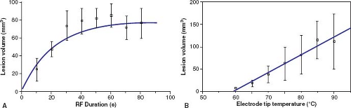 Figure 21.11 Lesion volume as a function of the duration of radiofrequency application (A) and the electrode tip temperature (B). Volume increases exponentially as a function of lesion duration. For (A) the tip temperature was held constant at 80°C. The time constant (time required to reach 63% of the ultimate asymptotic lesion size of 79 mm3) was 22 seconds. Ninety percent of the maximum lesion was reached by 45 seconds. Lesion volume appeared to grow linearly as a function of electrode tip temperature. Previous data in adult animals had shown linear increase in width and depth with tip temperature. |
 Figure 21.12 A: Test application with RF generator set to 50°C. Maximum temperature achieved is 45°C. Accessory pathway block occurs after 1.8 seconds, and power is turned off after 3.1 seconds. Accessory pathway conduction returns 3.6 seconds after turning off the power. B: After return of AP conduction, a full application is delivered with the RF generator set to 70°C. Peak temperature achieved is 56°C, and AP conduction block occurs at 1.5 seconds. |
Microwave
In contrast to RF heating, which primarily is resistive, microwaves heat with a propagating magnetic field that have the potential to heat tissue at a distance from the origin of the field. In vitro studies with microwave antennas have shown that the volume of heating is probably somewhat larger than that seen with RF, but is more dependent than RF on antenna construction characteristics, electromagnetic frequency, and geometry of the antenna in relation to the tissue (95). Although there are no commercial microwave systems available now, microwave ablation someday still may have a bearing on the treatment of VT or atrial flutter, where larger lesions may be necessary, and RF and cryo techniques have not been adequate.
Cryotherapy
Catheter-based cryotherapy was approved for use in the United States in 2003 for ablation of a variety of cardiac arrhythmias (96,97,98,99,100,101,102,103). Since then there has been a variety of reports in children, primarily focused on its use in AVNRT and other septal substrates (100,101,104,105,106,107,108,109,110,111,112,113,114,115,116,117,118,119,120,121,122). Cryoablation has several potential advantages over RF ablation, including (1) reversible cryomapping prior to
the production of a permanent lesion (99,123,124,125), (2) adherence of the catheter tip to the endocardium upon freezing, (3) a well-defined edge of the cryolesion, (4) minimal effects on adjacent coronary arteries (111,113,126,127), and (5) a lower incidence of thrombus formation (128). The first four of these issues are particularly relevant to small children because of the close proximity of a variety of critical cardiac structures to the ablation target and the reported potential for RF lesion growth in immature myocardium (65). In fact, the most common major complication during RF ablation in pediatric patients is AV block (34,61,129), and there appears to be a higher potential for coronary artery injury in this patient group (66,68,69,130,131), even during slow pathway modification (69) (see additional discussion under AVNRT). Both of these effects appear to be much less likely or absent with cryoablation (113). However, despite previous belief that cryoenergy does not have the same potential for RF lesion growth in immature myocardium as reported for RF energy (65), a report from Khairy et al. (116) demonstrated that, in fact, cryoenergy can produce nearly identical late lesion characteristics to RF energy in immature swine.
the production of a permanent lesion (99,123,124,125), (2) adherence of the catheter tip to the endocardium upon freezing, (3) a well-defined edge of the cryolesion, (4) minimal effects on adjacent coronary arteries (111,113,126,127), and (5) a lower incidence of thrombus formation (128). The first four of these issues are particularly relevant to small children because of the close proximity of a variety of critical cardiac structures to the ablation target and the reported potential for RF lesion growth in immature myocardium (65). In fact, the most common major complication during RF ablation in pediatric patients is AV block (34,61,129), and there appears to be a higher potential for coronary artery injury in this patient group (66,68,69,130,131), even during slow pathway modification (69) (see additional discussion under AVNRT). Both of these effects appear to be much less likely or absent with cryoablation (113). However, despite previous belief that cryoenergy does not have the same potential for RF lesion growth in immature myocardium as reported for RF energy (65), a report from Khairy et al. (116) demonstrated that, in fact, cryoenergy can produce nearly identical late lesion characteristics to RF energy in immature swine.
Typical cryotherapy systems allow for both ice mapping at a tip temperature of −30° to −40°C where the catheter adheres and nearby tissue loses electrical activity, but few cells are killed, and ablation at a tip temperature of less than −65°C where a lesion will be formed. It should be noted that in the United States due to regulatory issues, the only cryocatheter commercially available for ice mapping has a 4-mm tip. Once cells freeze, they expand and burst. After 4 minutes at the ablation temperature, a typical lesion size is 3 to 6 mm in diameter, smaller than those seen for RF. One of the contrasting features of cryoablation compared to RF is that there is a much larger zone of reversibility as the lesion expands because tissue cooling above the freezing point will lead to loss of electrical activation well prior to the loss of viability. This feature has dramatically enhanced the safety profile in clinical trials to date. In fact, despite frequent use of the technology for septal tachycardia substrates, there are no reports of AV block with cryoablation (99,100,101,102,132), even in children as small as 20 kg (117), in the presence of a His potential (106) (Fig. 21.13).
The primary disadvantage of cryoablation is that inherent in its high level of safety is a smaller lesion size than for RF ablation. For ablation of septal tachycardia substrates (AV node modification, anterior and posterior septal pathways), cryoablation success rates have been statistically similar to those for RF techniques (99,100,101,102,132). However, most operators are less aggressive with RF in septal areas and have had to be highly aggressive with cryotherapy to achieve success. Further, with one exception (109), even aggressive application of cryoenergy has not yielded similar success rates to RF for ablation of nonseptal APs. Although the data are limited in very small children and infants, anecdotal evidence suggest that cryoablation may be effective for all AP locations in these unique patient groups. Given the above considerations, as discussed below for individual arrhythmia substrates, the use of cryoablation is most important for septal substrates, small children and patients with abnormal anatomy where the precise location of the AV conduction system is not known.
Other
Any energy source that creates tissue heat has the potential to ablate myocardium in a similar manner to RF and microwave energy. Laser energy has been used to successfully ablate ventricular myocardium in both normal animals and humans with VT (133,134). The use of high-power ultrasound delivered through a catheter also has been reported as a means of heat ablation. One potential advantage might be the simultaneous use of diagnostic ultrasound to monitor lesion production (135). Finally, chemical ablation achieved by delivering a toxic agent such as alcohol into the coronary artery or vein supplying the myocardium responsible for
an arrhythmia has been used in both animals and humans; however, technical problems with selective delivery will probably prevent this technique from ever reaching widespread use.
an arrhythmia has been used in both animals and humans; however, technical problems with selective delivery will probably prevent this technique from ever reaching widespread use.
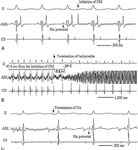 Figure 21.13 Successful cryoablation of a right anterior septal accessory pathway. A: ECG at the initiation of cryomapping during tachycardia. His potential can be seen on the ablation catheter. B: Termination of tachycardia during cryomapping. SVT terminates with VA block just 0.6 seconds before reaching −25°C and 47.4 seconds from the initiation of cryomapping. C: ECG at the termination of cryoablation shows sinus rhythm and a His potential still on the ablation catheter. CS, coronary sinus; ABL, ablation. |
Summary: Energy Sources
Several energy types are available currently for use in catheter ablation procedures. However, currently, for procedures in children, cryotherapy and RF energy with or without tip cooling appear to have the best safety and efficacy profile. Both energy sources can reproducibly control lesion characteristics through assessment of tip temperature and application time. In general, RF ablation is more effective, but for the reasons discussed above, cryoablation is safer. At this time, the balance between which source is used for which procedure depends on the arrhythmia substrate, the location of the target, including the proximity of the AV node and coronary arteries, and the preference of the center and operator.
Procedure: General
Preablation
Prior to the ablation procedure, standard electrophysiologic techniques should be used to identify the tachycardia mechanism and the location of the arrhythmia substrate. Differences from the standard study are related primarily to the actual mapping and ablation. Although not absolutely necessary, as discussed above, biplane fluoroscopy is very useful for precise two-dimensional localization of catheter tip positions. For most APs and AV node modifications, cameras are placed in the 30-degree RAO and 60-degree LAO positions, possibly with 10- to 15-degree caudal projections (see Fig. 21.3). In addition to camera angles, the development of deflectable-tipped catheters with closely spaced electrode configurations, which are now available from a number of manufacturers, has greatly facilitated accurate mapping and ablation in all parts of the heart.
Three-dimensional Electroanatomic Mapping
Over the past 10 years, a few novel methods have been introduced to simultaneously present 3-D, detailed electrical and anatomic information, facilitating mapping and reducing fluoroscopy exposure. The key features of these systems are: location tracking, signal timing, voltage assessment, and cataloging of all of these as the procedure takes place. There are multiple commercially available systems.
One, termed “nonfluoroscopic,” uses a technology similar to a global positioning system to identify the precise catheter tip position and orientation (Fig. 21.14) (CARTO, Biosense–Webster, Baldwin Park, CA, USA). Another, termed “noncontact,” uses the electrical signals in the blood pool of a cardiac chamber to derive
an inverse solution for the signals on the endocardial surface (Fig. 21.15) (EnSite—St. Jude Medical, St. Paul, MN, USA). Other systems provide simpler 3-D localizations of the catheter electrodes, using either impedance (NavX—St. Jude Medical, St. Paul, MN, USA—Fig. 21.16, and Loca-Lisa, Medtronic, Minneapolis, MN) or ultrasound localization (RPM, Cardiac Pathways), and can catalog catheter locations, timing, and voltage (see Fig. 21.17 for use during AV node modification) of signals during either mapping or ablation. Although location identification with impedance-based systems like NavX can be less accurate than the magnetic-based CARTO system, impedance-based systems do allow location and timing data from any catheter, consequently providing faster collection of both geometry and timing data. Consequently, most available systems now have a feature for impedance-based catheter location. The location tracking and cataloging feature is an important component of all 3-D systems, enabling the operator to be aware of where critical cardiac structures are, where applications have been made and their outcome.
an inverse solution for the signals on the endocardial surface (Fig. 21.15) (EnSite—St. Jude Medical, St. Paul, MN, USA). Other systems provide simpler 3-D localizations of the catheter electrodes, using either impedance (NavX—St. Jude Medical, St. Paul, MN, USA—Fig. 21.16, and Loca-Lisa, Medtronic, Minneapolis, MN) or ultrasound localization (RPM, Cardiac Pathways), and can catalog catheter locations, timing, and voltage (see Fig. 21.17 for use during AV node modification) of signals during either mapping or ablation. Although location identification with impedance-based systems like NavX can be less accurate than the magnetic-based CARTO system, impedance-based systems do allow location and timing data from any catheter, consequently providing faster collection of both geometry and timing data. Consequently, most available systems now have a feature for impedance-based catheter location. The location tracking and cataloging feature is an important component of all 3-D systems, enabling the operator to be aware of where critical cardiac structures are, where applications have been made and their outcome.
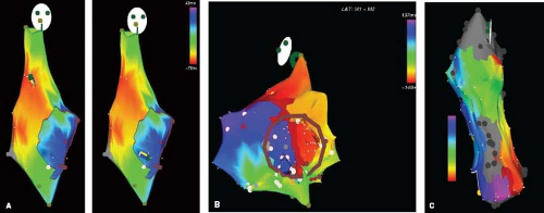 Figure 21.14 Three-dimensional mapping using the CARTO, Biosense nonfluoroscopic system. Color scales go from red-orange being the earliest activation to blue-purple being the latest (see scale bar in images). Gray represents an area of low voltage determined to be scar tissue. Each white dot represents one point where the catheter was place and activation times determined. The “face” at the top of each image shows the direction of the image. A: Sinus rhythm—RAO projection (see face) of the right atrium (RA) in an adult patient with prior repair of a VSD as a child. As expected with sinus rhythm, activation spreads from the anterolateral RA down toward the tricuspid valve. Activation lasts 122 ms, from 79 ms before to 43 ms after the fiducial point (bar at upper left). The two images show the mapping catheter tip in two different locations acquiring mapping data—high lateral RA on the left and low septal RA just behind the tricuspid valve on the right. A movie of this activation pattern as a propagation map (Video 21.1) demonstrates activation from the high lateral RA inferiorly and septally toward the AV Node region (B) Atrial reentry/flutter—LAO caudal image (see face) of the RA from Figure A. Tricuspid valve is now seen en face. Activation now proceeds from high anterior (red) down the septum, under the tricuspid valve and up the lateral RA wall. Activation now lasts 286 ms from 149 ms before to 137 ms after the fiducial point (bar at left), encompassing the entire cardiac cycle. This could be considered “typical” atrial flutter circling the tricuspid valve, but in a clockwise direction. A movie of the propagation map (Video 21.2) demonstrates conduction clockwise around the tricuspid. C: Atypical intraatrial reentry tachycardia (IART). Straight left lateral view of the septal surface of the RA (see edge of face with eyes forward). This 27-year-old patient with tricuspid atresia began to have IART soon after an atriopulmonary Fontan. After failing multiple medications and catheter ablation procedures, he underwent a right atriectomy and conversion to a lateral tunnel, but continued to have IART. After many subsequent years of failed medical therapy, he underwent mapping with the CARTO system demonstrating extensive atrial scarring and a single IART circuit was identified encircling a large septal scar or ASD patch. Note counterclockwise procession from red to yellow to green to blue to purple in this left septal view. A movie of the propagation map (Video 21.3) demonstrates the described conduction. Ablation was successful with an actively cooled tip system to block conduction in the inferior segment of the circuit (around the purple color). The patient has been asymptomatic since. |
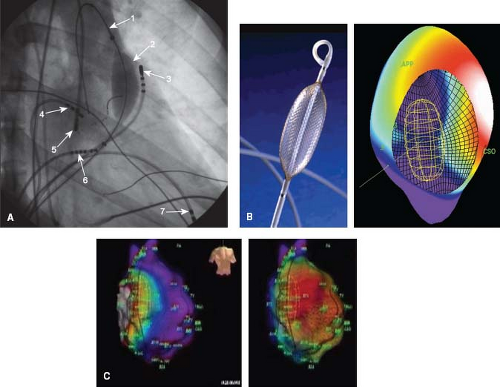 Figure 21.15 This figure shows the use of the EnSite 3-D intracavitary balloon noncontact mapping system (St. Jude Medical, St. Paul, MN). (A—top left) fluoroscopic right anterior oblique image is shown: (1) wire in main pulmonary artery placed to enable advancing the balloon/mesh catheter; (2) 64-electrode mesh inflated balloon in the right ventricular outflow tract (RVOT); (3) mapping/ablation catheter in RVOT; (4) high right atrial catheter; (5) retrograde mapping/ablation catheter in aortic root/sinus; (6) His catheter; (7) RV apex catheter. (B—top middle) Picture of mapping balloon shows a grid of wires criss-crossing the surface of the balloon, creating 64 individual electrodes. (top right) A computer reconstruction of the right atrium (CSO—coronary sinus os, APP—appendage) showing the endocavitary location of the balloon, and voltages on the endocardial surface at a single point in time. Activation is currently septal, shown by the white color above the CSO. (Bottom Panels) Right atrium during intraatrial reentry tachycardia (IART) in a 14-year-old boy after an atriopulmonary Fontan operation. The torso shows these are slight RAO projections. The atrium is large and bulbous. Although a little fuzzy, an area of presumed block secondary to a right lateral atrial scar is shown by a dark line along the anterolateral RA. The two images show posterior activation on the left and lateral activation on the right. The image of the balloon can be seen within the chamber. When played as a movie (Videos 21.4 to 21.6) the propagation map demonstrates the tachycardia proceeding around the scar inferior to superior on the anterior surface and superior to anterior on the posterolateral. In addition, the videos show that after ablation, pacing anterior and medial to the ablation line blocks laterally and proceeds posteriorly (Video 21.5), while pacing lateral to the ablation line blocks medially and proceeds posteriorly (Video 21.6). |
All of these systems have their limitations, including high cost for the CARTO catheter and EnSite balloon catheter; however, it is clear that they contribute significantly to our understanding of arrhythmias and their mechanisms, probably enhance success for complex cases (136,137,138,139,140,141), reduce radiation exposure (20), and make completely nonfluoroscopic procedures possible.
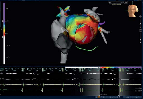 Figure 21.16 When imaging of multiple-catheter location is desired with or without the need for anatomic imaging detail, a mapping system such as NavX (St. Jude Medical, St. Paul, MN) or the latest fast mapping version of Biosense CARTO can be used. As shown this image of the left and right atria, all the catheter locations can be seen. The CS catheter is under left atrium in green, and an ablation catheter can be seen in the right middle pulmonary vein through the right atrium. The torso shows this is an LAO view. The system provides the ability to reflect real-time motion of catheter position, minimizing use of fluoroscopy and radiation exposure (see text). In addition, the catheters can be used to derive a “geometry” by sequential positioning of any of the catheter electrodes at multiple sites along the endocardial chamber. With the new Velocity system shown here the geometry can be made out of multiple segments to create a realistic 3-D model of cardiac structures. This image is also improved by merging the catheter acquired data with a CT image. Once the geometry is made, modifications like “cutting out” the tricuspid and mitral valves can be added, as shown here. Then signals can be acquired from any catheter electrodes and timing points derived to make a timing map. The timing map shown here is in the left atrium with early activation in pink red in the low lateral left atrium, probably near the left lower pulmonary vein. Activation proceeds anteriorly and superiorly to yellow and blue colors. The ECG and electrograms at the bottom include a window (right lower) that demonstrates where in the cardiac cycle the colors in the image correspond to. Although not shown in this patient, the location of ablation lesions or other points of interest can be easily added. (With permission St. Jude Medical, St. Paul, MN.) |
Fluoroscopic Exposure
Fluoroscopy as a risk factor for malignancy is an issue at every age, but may be of more theoretical concern in children and young adults for a variety of reasons. The most obvious of course is that the malignant potential of radiation exposure generally manifests itself after many years, so the risk in any population or individual will be related to the number of life years expected after the procedure, a number which increases with decreasing age of the exposure. A second factor is that radiation exposure in children who are still growing and have more cell divisions is generally considered to have more malignant potential than adults. Third, some of the longest and most complicated cases occur in adolescents and young adults with complex congenital heart diseases, a group already subject to excess radiation exposure due to multiple prior catheterizations for nonarrhythmia indications. Finally, as with all the other safety concerns addressed above, a general principal in the care of children with most arrhythmias is that safety concerns generally outweigh efficacy concerns because most tachyarrhythmias in children have a relatively benign long-term outcome.
Stay updated, free articles. Join our Telegram channel

Full access? Get Clinical Tree


