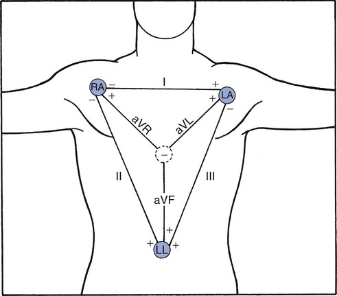
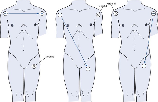
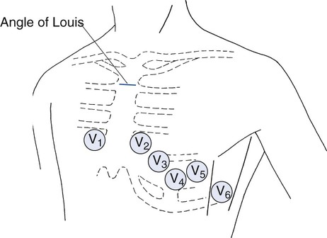
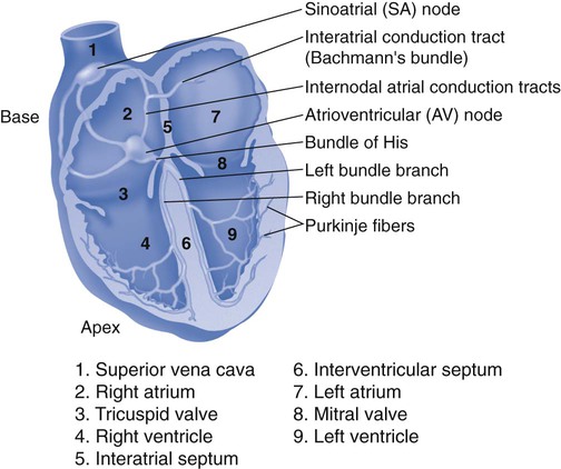
Chapter 6 1. Describe the purpose of the electrocardiogram (ECG). 2. Obtain a 12-lead electrocardiogram. 3. Describe the anatomic locations of standard lead placement. 4. Identify the numeric values assigned to the ECG paper. 5. Identify the various abnormal electrocardiographic recordings. In the ICU, monitoring a single lead, usually lead II, is the standard. The lead is displayed on the monitor with other diagnostic parameters. Many of the respiratory care treatments we perform, for example, the delivery of aerosolized adrenergic bronchodilators and suctioning a patient’s airway, may directly affect the heart. Therefore, the ability to continuously monitor a patient’s heart rate and rhythm is crucial. If a complete assessment of the heart’s electrical activity is needed in the patient complaining of chest pain that may be cardiac in origin, a 12-lead ECG will be ordered. Other complaints that may elicit the need for a 12-lead ECG are listed in Box 6-1. Through the use of 10 specifically placed electrodes, a 12-lead ECG allows for 12 different views of the heart’s electrical activity. Obtaining an ECG is a noninvasive procedure that can be quickly performed in the emergent setting. To obtain a 12-lead ECG, electrodes are placed in locations on the arms, legs, and chest of the patient. An electrode is a device that contains a conductive material. Electrodes are applied to the patient at specific locations to view the heart’s electrical activity. Figure 6-1 illustrates the view that the limb leads produce. The limb leads consist of four electrodes placed on the extremities giving you six views of the heart. These views are denoted as leads I, II, III, aVR, aVL, and aVF . Leads I, II, and III make up the standard limb leads and are considered bipolar leads. That is, their measurement of electrical activity happens in two different directions. Figure 6-2 illustrates the views obtained by leads I, II, and III. The augmented limb leads are unipolar. Electrical potential produced by the augmented leads is relatively small, so the ECG machine magnifies, or augments, the amplitude of the electrical potentials. The chest leads, referred to as precordial leads, are denoted V1, V2, V3, V4, V5, and V6. Unlike the limb leads, these leads are unipolar. That is, their measurement of electrical activity happens in only one direction. Lead placement is important. ECGs could be misinterpreted because of improper lead placement. Figure 6-3 illustrates proper chest lead placement. 1. Review the patient’s chart. 2. Verify the physician’s order or the facility’s protocol for standard of care. 3. Obtain, clean, and inspect the appropriate equipment prior to entering the patient’s room. 4. Follow personal protective equipment (PPE) requirements, and observe standard precautions for any transmission-based isolation procedure. 5. Identify the patient using two patient identifiers. 6. Introduce yourself to the patient and to the family. 7. Explain the procedure to the patient and to the family, and acknowledge the patient’s understanding. 8. Perform proper hand hygiene, and put on gloves, mask, and protective eyewear, as appropriate for the procedure. 1. Position the patient in the semi-Fowler position, and instruct him or her to breathe normally. 3. Clean and prepare the patient’s skin, as needed. 4. Apply self-sticking electrodes, and attach leads to the chest and the extremities. a. For the four limb leads: Place one on each wrist (RA, on right wrist or LA, on left wrist) and one on each ankle (RL, ground electrode on right ankle or LL, on left ankle). b. For the six chest leads: Follow this order beginning with V1: fourth intercostal space to the right of the sternum; V2: fourth intercostal space to the left of the sternum; V4: fifth intercostal space at the midclavicular line; V3: directly between leads V2 and V4; V5: level with V4 at the left anterior axillary line; V6: level with V5 at the left midaxillary line (directly under the midpoint of the armpit). 5. Turn on the ECG machine, and enter the patient’s demographic information. 7. Inspect the printout for clarity, and repeat, if necessary. 8. Disconnect the leads, clean the skin, and reposition the patient. 9. Discard any disposable equipment. 10. Remove the supplies from the patient’s room, and clean the area, as needed. 11. Remove PPE, and perform proper hand hygiene prior to leaving the patient’s room. Voltage, measured in millivolts (mV), also called amplitude, which is measured in millimeters (mm), is represented on the vertical axis of the paper. Voltage may be a positive or negative value. You cannot diagnose an ECG finding as abnormal, if you do not know what a normal finding looks like. Figure 6-4 is an ECG tracing of a normal sinus rhythm, and Figure 6-5 illustrates the normal conducting system of the human heart.
Electrocardiogram Interpretation
» Skill Check Lists
6-1 Obtaining a 12-Lead Electrocardiogram


Procedural Preparation
Implementation
6-2 Interpreting an Electrocardiogram


