Fig. 3.1
Hybrid operating room
3.3 Techniques
3.3.1 Chest Radiography
Simple anteroposterior chest radiographs may demonstrate signs of blunt aortic injury. The classic sign is a widened mediastinum. While this suggests bleeding, it is not specific to aortic injury. In 2011, Paterson and colleagues reviewed the available literature on imaging in vascular trauma and listed eight signs on chest X-ray of blunt aortic trauma (Table 3.1) [2]. A thoracic cavity to mediastinum ratio of 0.25 or an absolute mediastinal diameter of greater than 8 cm are markers of injury. Chest X-ray was relatively sensitive with a high negative predictive value [3–6].
Table 3.1
Plain chest X-ray findings suggestive of blunt aortic trauma
Mediastinal widening |
Aortopulmonary window opacification |
Displacement of trachea/esophagus or nasogastric/endotracheal tube to the left |
Left mainstem bronchus displacement downwards |
Rightward displacement of superior vena cava |
Left apical cap |
Left hemothorax |
Markers of injury severity (first rib fracture, scapula fracture, paraspinal rib fractures, sternal fracture) |
3.3.2 Ultrasound: Focused Assessment with Sonography in Trauma (FAST) and Duplex Ultrasonography
3.3.2.1 Theory
Modern ultrasound employs a “pulse-echo” technique with a brightness-mode (B-mode) display. Small pulses of ultrasound (sound waves above normal human hearing, i.e., 20,000 Hz or 20 KHz) are transmitted into the body. As ultrasound waves penetrate body tissues of differing densities and “acoustic impedances,” some are reflected back as “echo signals” but most penetrate deeper or are absorbed. The amount of ultrasound or “echo” returned after hitting an object is called its “acoustic impedance.” Lungs (mostly air) allow passage of almost all sound waves and have the lowest acoustic impedance; bone has the highest. The echo signals are processed to form “grayscale” (black and white) images.
Sound waves are described in terms of their frequency (cycles per second or hertz), wavelength (measured in millimeters), or amplitude (measured in decibels). Wavelength and frequency are inversely related. High-frequency sound has a short wavelength and vice versa. In medical devices, frequencies of 1–20 MHz are used. Selection of the correct ultrasound frequency for a given study is important. High-frequency ultrasound has high “axial resolution,” which means it can easily distinguish two structures at different depths along the path of those sound waves. It also has narrower “beam width” which aids “lateral resolution” or ability to distinguish two objects lying side by side. Unfortunately, high-frequency ultrasound is also rapidly absorbed or “attenuated.” So, it is most useful for superficial structures. Low-frequency/long-wavelength ultrasound, on the other hand, can penetrate more deeply due to a lower degree of attenuation and is better for deeper structures. Typically, a 2- or 3-MHz probe will be needed to examine the deep-lying aorta and iliac arteries, whereas a 5-MHz probe should image the infrainguinal vessels in normal-sized individuals. Higher-frequency probes (10–15 MHz) are used to image superficial nerves. Those used to ultrasound the anterior segment of the eye are 20–50 MHz.
As well as B-mode, modern units include pulsed-wave Doppler ultrasound to evaluate blood flow in arteries or veins (duplex ultrasonography). Christian Johann Doppler (1803–53) first described the “Doppler effect” in 1842. When a sound source moves towards a stationary receiver, the sound waves are crowded closer and closer together so that the wavelength is shorter and the frequency higher resulting in a higher pitch, e.g., a police siren approaching a pedestrian. The Doppler effect is used to determine the relative speed of an object to a sound source by bouncing sound waves off the object and measuring the shift in the frequency of the wave (also called the “Doppler shift”). Duplex ultrasonography is when pulsed Doppler is performed along with B-mode ultrasound because of its ability to measure flow as well as solid structures. Duplex can effectively image many vascular injuries such as arteriovenous fistulas, arterial disruption, intimal flaps, and pseudoaneurysms.
3.3.2.2 Equipment
Modern ultrasound units comprise a transducer probe, a central processing unit (CPU), display screen, and transducer pulse controls. The transducer probe sends and receives sound waves using the piezoelectric effect. In 1880, French physicists Jacques and Pierre Curie found that, in crystalline materials (e.g., quartz, ceramics, bone), mechanical pressure generates an electric charge. This is “reversible”—applying electrical charge to these crystals slightly alters their shape.
In a transducer probe, there are piezoelectric crystals (most commonly lead zirconate titanate or PZT). When current is applied to them, they change shape rapidly. These “vibrations” emit sound waves. Conversely, when these crystals are struck by sound waves such as those reflected back from a solid body, they generate electrical currents. Between the crystal and the skin is a “matching layer” of aluminum powder in epoxy resin or rubber that decreases the acoustic impedance difference between the crystal and the skin. An acoustic lens focuses emitted sound waves.
The central processing unit (CPU) generates the electric currents that cause vibrations in the transducer probe’s crystals. It also processes the electrical pulses produced by the reflected sound waves and generates grayscale images on the monitor.
Finally, the transducer pulse controls alter the electrical currents generated by the CPU. This changes the frequency and duration of ultrasound pulses produced by the transducer probe. Three parameters that can be adjusted: depth, frequency, and “gain.” The depth of tissue imaged can be adjusted on the machine by changing the frequency of the emitted ultrasound. Variable frequency probes allow such changes within a narrow range, e.g., 8–13 MHz. Ultrasound probes transmit ultrasound 1 % of time and “listen” for echoes 99 % of the time. Increasing the “gain” on the ultrasound machine increases signal amplification of the returning ultrasound to compensate for tissue attenuation.
3.3.2.3 Focused Assessment with Sonography in Trauma (FAST)
Focused assessment with sonography in trauma or “FAST scanning” is the practical application of B-mode ultrasound in trauma. It is used to detect free fluid in the peritoneal cavity following blunt abdominal trauma [7]. It has supplanted procedures such as “four-quadrant tap” and diagnostic peritoneal lavage (DPL) to diagnose intra-abdominal hemorrhage. It is noninvasive, is easily repeated, and is not hampered by previous laparotomy or thoracotomy scars. Using a 3.5-MHz probe, four areas (the four Ps) are examined: perihepatic, perisplenic, pelvic, and pericardium.
FAST scanning is easily taught. Shackford concluded that only ten scans were needed to become proficient [8]. The sensitivity of FAST ranges from 29 to 100 % and specificity from 94 to 100 % [8–14]. As it can be rapidly performed, many see the real role of FAST scanning as confirming the site of injury in a hemodynamically unstable patient. However, its role in the management of the hemodynamically stable patient with blunt abdominal trauma has been questioned, especially if CTA is readily available [9]. In the largest series, from Omaha, Nebraska, involving 2,980 patients, Natarajan reported a sensitivity of only 41 % in blunt abdominal trauma patients for FAST scanning (Table 3.2) [11]. The authors concluded that focused assessment with sonography for trauma in hemodynamically stable blunt trauma patients “seems not worthwhile” and that it should be reserved for hemodynamically unstable patients with blunt trauma. One might suggest that it will add little here, either, as these patients are going to the operating room regardless of their FAST scan findings. False negatives in FAST scanning are not confined to tyros. Even experienced operators may have a missed injury rate in these patients of 10 % [15]. Despite this, FAST scanning will continue to have a role. For most experienced emergency room physicians, it adds little time to assessment and will, more often than not, provide useful information.
Table 3.2
Sensitivity and specificity of focused assessment with sonography in trauma (FAST)
Study | Number | Sensitivity (%) | Specificity (%) | NPV (%) |
|---|---|---|---|---|
Smith (2013) [10] | 166 | 90 | 100 | N/A |
Natarajan (2010) [11] | 2,130 | 43 | 99 | 94 |
Gaarder (2009) [9] | 104 | 62 | 96 | 89 |
Tsui (2008) [15] | 242 | 86 | 99 | 98 |
Nural (2005) [79] | 454 | 86.50 | 95.40 | 98.70 |
Dolich (2001) [80] | 2,576 | 86 | 98 | 98 |
Becker (2010) [81] | 3181 | 75 | 98 | 95 |
Kim (2012) [82] | 240 | 61 | 96 | 83 |
3.3.2.4 Duplex Ultrasonography
While FAST scanning can be performed competently with relatively little training, duplex ultrasonography, especially in trauma patients, requires a much higher level of expertise. In trauma, duplex is used for extremity and cervical injuries and to follow conservatively managed injuries. But it is highly operator dependent and can be time-consuming. It is also limited by soft tissue defects, subcutaneous air, and casts applied to stabilize fractures or ligamentous injuries.
In the management of head and neck trauma, duplex is effective in screening for carotid and vertebral injury. In patients with penetrating neck injuries, it has been shown to have a 90.5–100 % sensitivity for detecting intimal flaps, dissections, occlusions, and pseudoaneurysms with a specificity of 85–100 % [16–19]. Important limitations, however, are an inability to image the distal internal carotid artery above the level of the mandible (zone III) and the common carotid artery proximal to the clavicle (zone I) [20]. Nonetheless, the Eastern Association for the Surgery of Trauma currently recommends that for hemodynamically stable patients, with penetrating zone II neck injuries, Duplex (and CTA) can safely replace conventional angiography [21]. This was based on several retrospective and prospective studies [16, 22, 23].
Initial reports on the use of duplex for extremity vascular injuries were encouraging. Knudson in 1993 reviewed his group’s experience with 86 extremity injuries and found a 100 % true positive rate [23]. However, more recent assessments have been less enthusiastic. Felliciano in 2011 reported sensitivities in the 50–100 % range [24]. Unlike FAST scans, in most ERs, duplex is not an extension of the stethoscope and will not be available “out of hours.”
3.3.3 Catheter Angiography
The first angiograms were hazardous affairs. In 1927, a “colorful” Portuguese physician Antonio Egas Moniz performed the first cerebral angiogram (Fig. 3.2) [25]. Moniz, who was (somewhat controversially) awarded the 1949 Nobel Prize for championing prefrontal lobotomy, performed a direct cutdown onto the carotid arteries to obtain exposure [26, 27]. He used strontium bromide as the contrast agent. Four of the first six had complications and one died. In 1931, he began to use colloidal thorium oxide as his contrast agent, which unfortunately, as a perpetual α-particle emitter, is carcinogenic, and has a biological half-life of 500 years. In 1949, a patient shot him and he was wheelchair bound until his death in 1955. In 1929, Reynaldo Cid dos Santos performed the first aortogram, also in Lisbon [28]. He performed it with a long needle using surface anatomy landmarks. A safer technique for percutaneous femoral access was developed by Sven Ivar Seldinger at the Karolinska Institute in Stockholm in 1953 [29]. Catheter-based interventions began with Charles Dotter in 1964, and coronary balloon angioplasty was first performed by Andreas Gruentzig in 1977 [30, 31].
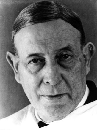
Fig. 3.2
Antonio Egas Moniz (1874–1955). Pioneer of angiography
3.3.3.1 Theory
Contrast media and fluoroscopy are the essentials of catheter angiography. Current contrast agents are iodine based. Iodinated contrast agents are either “ionic” or “nonionic.” Ionic contrast agents were introduced in the 1930s. They have a high osmolality (osmoles per kilogram of solvent) and solubility but low viscosity. They are also known as high-osmolar contrast media (HOCM) as their osmolality is 7–8 times that of plasma. All are based on a benzene ring containing three iodine atoms, which dissociate in water into cations and anions, hence the term “ionic.” They are hypertonic to enable them to achieve a high-enough concentration of iodine to provide intravascular contrast. However, such high osmolalities and viscosities (e.g., Hypaque has an osmolality of 1,500–1,700 mOsm/kg compared to 275–295 mOsm/Kg for human plasma) can cause vasodilatation, heat, pain, osmotic diuresis, and myocardial depression. Nonionic or iso-osmolar contrast media (IOCM) consist of two benzene rings, each with three iodine atoms, which are covalently bound and do not dissociate in water (hence “nonionic”). The osmolality of a typical nonionic contrast agent, such as Visipaque, is 300 mOsm/Kg. As a result, IOCMs have fewer side effects. Typically, ionic contrast agents will be associated with a 1:40,000 incidence of fatal anaphylaxis compared to 1:170,000 for nonionic contrast agents.
The second component is a fluoroscope with an image intensifier to display real-time X-ray images. A patient is placed between an X-ray source and a fluorescent screen (a transparent screen coated on one side with a phosphor that fluoresces when exposed to X-rays). The screen is coupled to an image intensifier (a vacuum tube device that converts low levels of light from the fluoroscope into visible light). A charge-coupled device (CCD) video camera converts the incoming light photons into digital images. Digital flat-panel detectors are the modern incarnation of the image intensifier/video camera combination. Digital subtraction is where an initial mask image, containing bone, is taken, followed by a contrast study. The “mask” image is then removed from the subsequent images. There are two imaging modes on most contemporary machines: “fluoroscopy” and “acquisition” or “cine” mode. Fluoroscopy provides a real-time image of sufficient quality to guide catheter and wire placement. Typical frame rates are 3–5 frames per second. Acquisition (cine) mode, which is sometimes called “run” or “record” mode, generates much higher-quality images—at the expense of much higher radiation doses. A typical acquisition per-frame dose of radiation is 15 times that of fluoroscopy.
3.3.3.2 Equipment
The equipment for trauma angiography is no different from that required for elective angiography. For best results, especially if interventions are anticipated, these studies are best performed in a fully stocked interventional radiology suite (or hybrid room) with trained personnel.
3.3.3.3 Technique
In trauma patients, the likely point of access will be the common femoral artery. Local anesthesia over the common femoral artery is used with monitored sedation, if the patient is hemodynamically stable. In difficult cases, ultrasound guidance is useful to facilitate access. Either way, a Seldinger technique is used to access the artery. Aggressive hydration and use of half-strength contrast help to minimize renal insult in patients with chronic kidney disease (CKD). In elective patients with CKD, CO2 angiography is useful but is unlikely to be as helpful in trauma due to its lack of fine detail.
3.3.3.4 Angiography in Vascular Trauma
Catheter angiography is still an excellent technique in vascular trauma. It is a dynamic study, so it will demonstrate hemorrhage and allow for deployment of covered stents or coils to staunch bleeding (Fig. 3.3).
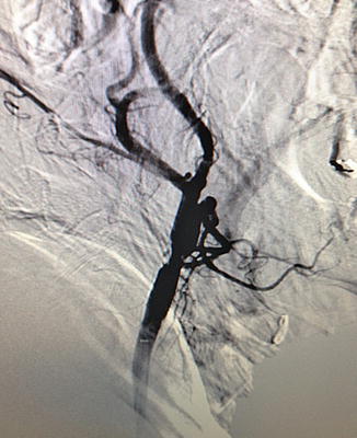
Fig. 3.3
Carotid arteriogram
In cervical trauma, catheter angiograms are especially useful in imaging zone I or zone III injuries. Usually, selective catheterization of the carotid and vertebral arteries is performed for a complete study, and multiple views are taken, including anteroposterior, lateral, and oblique views. However, diagnostic carotid angiography is not routinely performed now for carotid stenosis due to reliable, noninvasive imaging. And carotid stenting, despite its proponents, is still confined to a minority of centers. Hence, expertise is not as widely available as it once was. Catheter angiography also carries risks. Even in the best hands, stroke-mortality risk from elective procedures is 1.2 % [32].
In the past, screening angiography was advocated for penetrating neck injuries in place of blind exploration. It is certainly very sensitive in detecting arterial injuries but, as a screening tool, only provides positive findings in 7 % of stab wounds and 27 % of gunshot wounds [33].
Catheter angiography is still the “gold standard” for diagnosing traumatic carotid dissection following blunt trauma. Untreated, traumatic dissection is associated with a stroke rate of 35 % [34]. Prompt diagnosis and treatment before symptoms of ischemia are crucial. But the incidence of carotid and vertebral artery dissection in patients with serious markers of blunt cervical trauma such as LeFort II or III facial fractures and skull base fractures is only 29 %, meaning 71 % of patients will undergo an invasive procedure (and potentially fatal) test for no benefit [35]. Cervical CTA, on the other hand, is rapid, noninvasive, and virtually risk-free. It has been reported to be 100 % sensitive, even using 16-slice scanners, and aggressive CTA screening has been shown to reduce stroke due to blunt cervical vascular injury fourfold with no adverse outcomes attributed to the diagnostic test [36, 37]. Consequently, it has largely superseded conventional angiography in these patients.
Blunt trauma is the most common form of thoracic aortic trauma (Fig. 3.4). Most (85 %) of patients with thoracic aortic trauma die at the scene of the accident, and if untreated, most of the remaining 15 % die within 3 days. Aortography was formerly the gold standard. However, in the presence of near-complete aortic transection, it may not be possible to pass a catheter past the injured area and a brachial approach is required. Although there are no reports of catheters penetrating an area of aortic injury, there are reports of full rupture of the aorta after “power” injection [38]. Neither will it display associated venous or soft tissue injuries. However, it will allow for intervention and stenting of aortic injuries. It is usually performed via a femoral approach. For abdominal aortic trauma, the same arguments apply, although for injuries to visceral or renal arteries, catheter angiography will allow treatment of vessels that surgically may be relatively inaccessible.
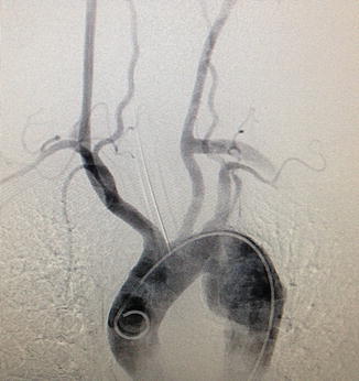
Fig. 3.4
Thoracic aortogram. A marker catheter is located within the arch of the aorta. The innominate, left common carotid, and left subclavian arteries are well seen, as are the vertebral arteries
Peripheral arterial injuries occur in 1–2 % of major domestic trauma patients but are more frequently encountered in modern warfare (Fig. 3.5). Again, catheter angiography was once regarded as the gold standard. In 1991, Frykberg studied 135 patients by angiography who had a normal vascular examination [39]. He found 18 % had occult vascular injuries, but only one of these actually ever came to surgery; the rest resolved. The complication rate for peripheral angiography ranges from 0.37 to 9.1 % with mortality of 0–0.7 % [40–42]. It has a sensitivity of 95.5–98.3 % and a specificity of 97.7–98.5 % [43, 44].
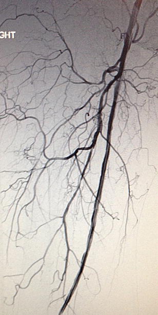
Fig. 3.5
Completion arteriogram of right lower extremity. A patient with a dissection of his above-knee popliteal artery with completion arteriogram following an endovascular intervention
3.3.4 Magnetic Resonance Angiography (MRA)
Magnetic resonance angiography (MRA) was used, in the past, for vascular patients with contrast allergies or renal impairment who could not tolerate conventional contrast studies. However, following reports linking gadolinium to the development of nephrogenic systemic sclerosis, enthusiasm has waned [45–47]. Long image acquisition times (20–30 min) and substantial improvements in the quality of CTAs have militated against MRA’s wider use. Nonetheless, there are still instances in vascular trauma where MRA is useful.
3.3.4.1 Theory
While the language of conventional angiography is familiar to all vascular specialists, MRI terminology is often impenetrable to those without a strong physics background. In fact, the theory and terminology need not be so intimidating. Humans contain a lot of water (H2O), and each molecule of H2O contains two hydrogen atoms each with a single proton. When mammalian tissue is subjected to a strong magnetic field, the average magnitude and direction (“magnetic moment”) of the protons become aligned with that of the magnetic field. A radiofrequency current is briefly turned on which is absorbed by the tissue and “flips” the spin of the protons. When it stops, the protons’ spins return to baseline. During this “relaxation,” a radiofrequency signal is generated that can be measured by the receiver coils. As protons in different tissues return to their equilibrium state at different relaxation rates, MRI can detect the different contrasts of soft tissues, which makes it especially useful for imaging neural, muscular, and connective tissues.
When the radiofrequency wave is switched off, the protons relax in two different ways. One involves a return of protons to their original alignment with the static magnetic field called “longitudinal” or “spin-lattice” relaxation and is characterized by a time constant T 1. This gives rise to T 1-weighted images.
The second form of relaxation is best compared to what occurs when a child’s spinning top loses its momentum and starts spinning erratically before coming to rest. In MRI, what occurs is called loss of “synchrony of precession” of protons (precession is the change in orientation of the rotational axis of a rotating body, e.g., the axis of a rotating toy top changes as it spins). Before the radiofrequency wave is applied, the precessional orientation of the protons is random. When the wave is applied, it brings the protons into synchronous precession (“in phase”). When it is switched off, the protons revert to their asynchronous, random state, collide with their neighbors, and give up energy. This is called “transverse” or “spin-spin” relaxation and is represented as a time constant T 2. It gives rise to T2-weighted images.
In T 1-weighted images, fluids are very dark and fatty tissues are very bright. Clear boundaries can be seen between the tissues, so they are known as “anatomy” scans. In T 2-weighted scans, fluids are bright and fatty tissues are gray. Abnormal fluid collections show up as bright against the darker normal tissue. They are also called “pathology” scans. Manipulating the radiofrequency wave preferentially produces T 1 and T 2 images.
Whereas contrast agents in conventional angiography exhibit a direct dose-dependent effect on the image (the more contrast in the vessel, the more intense the image), contrast agents used in MRI “indirectly” affect the image by shortening T 1 and T 2 relaxation times. In fact, MRI contrast agents are paramagnetic molecules (molecules with unpaired electrons, e.g., Fe++ has two unpaired electrons). These unpaired, negatively charged, electrons facilitate the relaxation of the positively charged hydrogen protons following radiofrequency stimulation. As gadolinium has seven unpaired electrons, it is very effective. However, problems with gadolinium have led to a search for newer, safer contrast agents. In 2012, Sitharman and his group described graphene oxide nanoribbon (GONR)-based contrast agents as a safe alternative to gadolinium [46].
3.3.4.2 Equipment
MRI scanners must produce a uniform magnetic field (not varying by more than 0.0001 %). MRI magnets are strong. The Earth’s magnetic field is 0.00005 T; small bar magnets are 0.01 T. The magnets used in MRI scanners are 0.5–3.0 T. An MRI with a 3.0-T-strength magnet may be referred to as a “3-T MRI” or “3-T MRI.” Lower field strengths (0.3 T) are obtained with permanent MRI magnets. These are used in “open” MRI scanners, for claustrophobic patients. Higher field strengths can be achieved only with superconducting magnets.
3.3.4.3 Technique
Contrast-enhanced MRA is the technique of choice for modern imaging. Not everybody is suitable for MRA. Pregnancy is a contraindication, as gadolinium crosses the placenta and the effects of heat and noise on the fetus are not known. If the patient has shrapnel or bullet and grenade fragments, these will be contraindications. Pacemakers and ferromagnetic surgical implants are also contraindications. Stainless steel skin staples are contraindicated, but it is noteworthy that titanium (of which many surgical clips are composed) is a non-ferromagnetic substance. Peripheral vascular and coronary artery stents and inferior vena cava (IVC) filters are composed of nitinol and are not contraindications. However, transvenous pacing leads and pulmonary artery catheters, while not containing ferromagnetic substances, may heat and cause thermal injuries and are not recommended. Peripheral access is required and anxious patients may need intravenous conscious sedation with midazolam. It takes 20–40 min to complete an examination, and it is important that the patient can cooperate by remaining still. In trauma patients, with other injuries, this may be difficult.
3.3.4.4 CE-MRA in Vascular Trauma
Given the duration of each study and need for patient cooperation, patients must be stable to undergo these studies. Also, the list of contraindications listed above may preclude some trauma patients. MRA in trauma seems to be limited to assessment of blunt cervical trauma. Ren and colleagues assessed the use of MRA in 319 patients with blunt cervical trauma and found that it effectively diagnoses vertebral artery injury, but previous studies showed that it had only 50 % sensitivity for carotid artery injury and 47 % for vertebral artery injury compared to carotid angiography [35, 48]. There are no reports of the use of MRA to assess thoracic or abdominal vascular injuries or peripheral arterial trauma.
3.3.5 Computerized Tomographic Angiography (CTA)
Sir Geoffrey Hounsfield pioneered CT scanning at EMI (Electric and Music Industries Ltd.) Laboratories in the 1960s [49]. He came up with the idea that it might be possible to determine the contents of a box by taking X-rays at all angles around the object. Allan Cormack (1924–1998), a South African physicist, had already described how radiation absorption or attenuation differed between tissues and was not uniform, as had previously been assumed [50]. The first CT scan was performed on a woman with a frontal tumor at the now defunct Atkinson Morley Hospital, a specialist neurosciences hospital, in London. However, EMI, in the 1960s, was mainly a successful music company (they were the Beatles’ record label), and they quickly lost their leadership in CT scanning. Cormack and Hounsfield jointly received the Nobel Prize for Medicine in 1979.
3.3.5.1 Theory
The basic theory of CT is relatively simple. An X-ray source is used to irradiate a thin slice of tissue. The X-rays are attenuated (or lose their intensity) to varying degrees, depending on tissue absorption. An X-ray from a single source, however, will not be adequate to allow three-dimensional reconstruction. It is necessary, as Hounsfield knew, to irradiate the object from all directions in a single plane and then to reconstruct the images. Johann Radon (1887–1956) first elucidated the mathematics. In 1917, he described the radon transform (the integral of a function over straight lines) [51]. But practical application required the invention of modern computers. Every CT slice is subdivided into a matrix of up to 1024 × 1024 volume elements or voxels. Each voxel is X-rayed numerous times during a CT scan. This allows the “attenuation coefficient” of that voxel to be calculated, which is how easily a beam of light, sound, or other energy penetrates a material. The attenuation values for each voxel are digitally represented as pixels. Each pixel (and hence each voxel) has a radiodensity value called a Hounsfield unit (HU). Water is “0” Hounsfield units and air “−1,000.” Dense bone will have a value of “+3,000.” On a gray scale, air is black and bone white.
3.3.5.2 Equipment
The first CT scanners acquired images a single slice at a time (sequential scanning). This was time-consuming. In 1990, slip ring technology was developed which led to the development of the spiral CT scanner. In spiral scanners, the X-ray tube rotates continuously around the table, while an array of detectors measures the transmitted radiation. This was followed by multidetector row computed tomography (MDCT) in 1998. Current 64-slice multidetector row computed tomography, or 64-MDCT, allows for rapid scanning time and thinner slice thickness. The most recent development in CT scanners has been “dual-source” CT technology. Dual-source CT uses two X-ray tubes and two detectors arranged at 90° angles, allowing reconstruction of cross-sectional images at one quarter of the gantry rotation time. It is particularly useful for cardiac scans, allowing CT to be performed without lowering heart rates by administration of β-blockers, as is usually the case. Imaging with dual-source CT even allows determination of the average atomic number in each voxel. This is significant as it allows differentiation between calcium (atomic weight 40) in an arterial wall and iodinated contrast medium (atomic weight of iodine 127) and nitinol (atomic weight of nickel 58.7, titanium 48), which are difficult to otherwise differentiate, even using 64-MDCT.
3.3.5.3 Technique
For a CTA, the patient is injected with 50–100 mL of iodinated contrast material at 5 mL/s, followed immediately by a 40-mL 0.9 % saline bolus at 5 mL/s through an 18- or 20-gauge catheter located in an antecubital vein. There are four phases to CT scanning: precontrast, arterial, venous, and delayed phases. Precontrast studies detect vascular calcifications, metallic implants, surgical clips, and hematomas. The arterial phase scan is done 30 s after contrast injection. Modern CTs use bolus-tracking software to monitor contrast enhancement of the aorta. Splenic and hepatic injuries can be detected in the venous phase, which is performed 70–120 s after the end of the initial injection. A third scan (delayed phase) is done 3 min later in the pyelogram phase if renal trauma is suspected. To detect suspected venous injuries, dual-phase scanning must be used.
An MDCT angiogram generates more than a 1,000 axial images. Initial assessment is done on the basis of the axial images. However, it is also possible to “post-process” these into images that approximate normal anatomy. A post-processing workstation is used to manipulate these data. Modern 64-slice CT scanners will offer reconstructions using four techniques: maximum intensity projection (MIP), volume rendering (VR), multiplanar reconstruction (MPR), and curved planar reconstruction. Each has its advantages. In the trauma situation, this may not be possible in a timely manner nor may it alter management.
3.3.5.4 CTA in Vascular Trauma
The sensitivities and specificities of CTA for detecting vascular damage in trauma patients in all anatomical territories are very high. There are several caveats, however. Artifacts from metallic foreign bodies in ballistic injuries or underlying vascular calcification may hinder accurate interpretation. Technical problems, such as inaccurate contrast timing, patient movements during the scan, and injection-site artifacts may also render the scan useless. However, these pitfalls are not frequent, especially in civilian injuries. If foreign bodies are a problem, one still has the option to perform a catheter angiogram.
In a recent excellent review in 2011, Patterson reviewed the use of all modalities in assessing vascular trauma and concluded, on the basis of a systematic review of the literature, that CTA should be the first-line investigation for all patients with suspected vascular trauma without “hard signs” mandating immediate surgery [2]. The results from most modern series are certainly impressive in all territories (Tables 3.3, 3.4, 3.5, and 3.6).
Table 3.3
Efficacy of CTA in the diagnosis of blunt cervical trauma
Reference | Year | Mode | No. screened | Sensitivity (%) | Specificity (%) | PPV (%) | NPV (%) | Incidence (%) | Conclusion |
|---|---|---|---|---|---|---|---|---|---|
Hughes et al. [82] | 2000 | MRI | 189 | – | – | – | – | 0.2 | Incidental BCVI is relatively common; MRI should be used to screen for BCVI |
Miller et al. [35] | 2002 | CTA versus MRI | 216 | 47/50a | 99/99a | – | – | 1.0 | CTA and MRI are insufficiently accurate to detect BCVI |
53/47a | 100/97a | – | – | ||||||
Mutze et al. [83] | 2005 | US | 1,471 | 38.5 | 100 | – | – | – | US has inadequate sensitivity; CTA is accurate |
CTA | 407 | 100 | 99.1 | – | – | ||||
Eastman et al. [36] | 2006 | CTA versus angiography | 146 | 97.7 | 100 | 100 | 99.3 | – | CTA can be used to screen at-risk patients for BCVI |
Biffl et al. [84] | 2006 | CTA versus angiography | 331 | – | – | – | – | 0.7 | No patient with normal CTA developed symptoms subsequently |
Berne et al. [85] | 2006 | CTA | 435 | – | – | – | – | 1.2 | 16-slice CTA is more accurate than 4-slice |
Utter et al. [86] | 2006 | CTA | 372 | – | – | 19 | 92
Stay updated, free articles. Join our Telegram channel
Full access? Get Clinical Tree
 Get Clinical Tree app for offline access

|