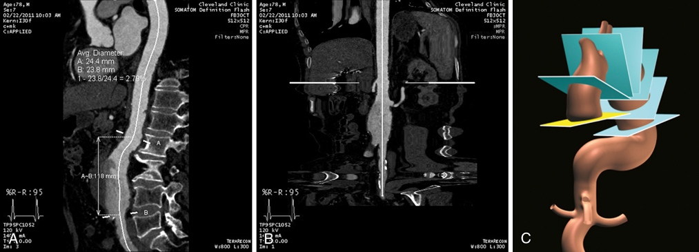
Usually MIP images define the borders of a vessel, allowing the geometric center to be calculated. The dots representing the vessel’s center in 3-D space are connected to form the CLF. The vessel can be projected along a curved CLF (Figure 1A) or a straightened CLF (Figure 1B), allowing length measurements to be obtained. The vessel’s diameter is also most accurately measured using CLF projections. An image is reconstructed that is perpendicular to the CLF, and the diameter of the vessel is measured from this image (Figure 1C). This obviates the need to obtain maximum and minimum diameters of vessels from images that likely cut obliquely through a vessel, which provides an inconsistent and less accurate way to measure the diameter of aneurysms or stenoses.
Computed Tomography and Computed Tomographic Arteriography in the Evaluation of Abdominal Aortic Aneurysms
Reconstruction

![]()
Stay updated, free articles. Join our Telegram channel

Full access? Get Clinical Tree


Thoracic Key
Fastest Thoracic Insight Engine
