Clinical Management of Patients with Implantable Cardioverter Defibrillators
In the wake of numerous scientific studies demonstrating the clinical benefit of implantable cardioverter defibrillators (ICDs), millions of these devices have been implanted worldwide. A thorough understanding of basic ICD functions, ICD programming, and management of common ICD clinical scenarios is essential, not just for the electrophysiologist but for all health care providers who care for patients with ICDs.
Informed Consent
Patients must fully understand the indications for ICD implantation, the potential acute and long-term complications associated with ICD implantation, as well as issues related to device reliability and performance. It is worthwhile having a formal discussion of estimated risks for arrhythmic death based on patient characteristics (see Chapter 14). An equally important part of the discussion should address the fact that ICDs may prolong their life, but particularly in those with advanced heart failure this involves a shift in the mode of death from sudden cardiac arrest to intractable heart failure (see Table 16-1).
Longer-term issues include infection and/or erosion requiring device explant, device or lead malfunction, and inappropriate shock (∼4% per year in sudden cardiac death in heart failure [SCD-HeFT]). In the SCD-HeFT cohort,
14% of patients experienced a clinically significant complication due to the ICD over 5 years.
14% of patients experienced a clinically significant complication due to the ICD over 5 years.
TABLE 16-1 Periprocedural Complications
| Complication | Percentage Risk |
| Any complication | 5–11 |
| Mechanical complication with lead or pocket revision | 4–7 |
| Significant hematoma | 2–3 |
| Pneumothorax | 1 |
| Acute infection | 0.4–1.4 |
| Cardiac perforation/tamponade | 0.3 |
| Death | <1 |
Components of the Implantable Cardioverter Defibrillator
The ICD consists of several components: sensing electrodes to provide both rate and arrhythmia sensing, defibrillation electrodes, and the pulse generator which consists of the battery, capacitor, and controlling circuitry.
Lead technology has evolved rapidly since the introduction of the first ICD systems. The earliest systems used standard pacemaker leads to pace and sense in combination with separate defibrillation leads that delivered therapeutic shocks. Current models combine these functions into a single lead. Some leads employ true bipolar sensing between the distal tip of the electrode and a ring electrode just proximal to the tip, whereas other leads use integrated bipolar sensing between the tip and the distal portion of the defibrillation coil. Integrated bipolar leads have a larger “antenna” over which they sense cardiac signals; as such there is greater potential for inappropriate oversensing of noise such as diaphragmatic myopotentials. At implant, the right ventricle (RV) sensing lead should have a local electrogram amplitude (“R wave”) of at least 5 mV to ensure adequate sensing of lower amplitude fibrillatory waves during ventricular fibrillation (VF).
The defibrillation electrodes, once patches that were attached to the epicardial surface, are now coils that are an integrated part of the transvenous lead. One coil is in the distal portion of the lead and lies along the inferior wall of the RV. The shock vector is between the pulse generator, usually implanted in the pectoral site, and the RV coil. Many leads include a second coil in the section within the superior vena cava (SVC), which provides a broader tripolar
shock vector with lower impedance, usually resulting in lower defibrillation thresholds (DFTs) (see Fig. 16-1).
shock vector with lower impedance, usually resulting in lower defibrillation thresholds (DFTs) (see Fig. 16-1).
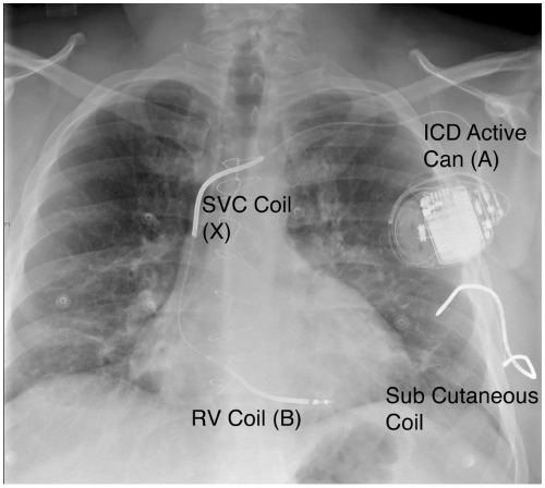 FIGURE 16-1. Chest x-ray demonstrating a standard dual coil implantable cardioverter defibrillator (ICD) lead with the proximal and distal coils labeled. There is a subcutaneous coil which originates in the pacemaker pocket and is tunneled subcutaneously along the lateral chest wall in a posterior orientation. In this case, the coil is not optimally positioned in the posterior orientation because it has migrated backward as often occurs. SVC, superior vena cava; RV, right ventricle. |
The pulse generator consists of the metal housing that is an active part of the shock vector, internal circuitry, the battery which generally lasts for 5 to 7 years, and a high voltage capacitor for storing and delivering the charge.
Device Features
All ICDs perform pacing functions similar to pacemakers for treatment of bradyarrhythmias. In addition, ICDs are able to treat tachyarrhythmias through a number of different modalities: antitachycardia pacing (ATP), cardioversion, and defibrillation (see Figs. 16-2,16-3, and 16-4). The sequence and manner in which these therapies are delivered is programmable and can be
tailored to each patient depending on the specific clinical scenario. Such factors might include a known history of ventricular tachycardia (VT) with a specific tachycardia cycle length, or a high or low DFT.
tailored to each patient depending on the specific clinical scenario. Such factors might include a known history of ventricular tachycardia (VT) with a specific tachycardia cycle length, or a high or low DFT.
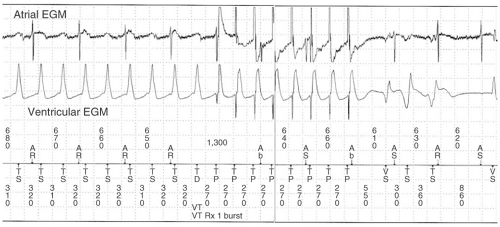 Figure 16-2. Implantable cardioverter defibrillator (ICD) electrograms from a dual chamber device demonstrating ventricular tachycardia at 320 msec. It is detected and antitachycardia pacing at 270 msec for 8 beats is delivered with successful termination of the ventricular tachycardia (VT). The atrial marker channel demonstrates (atrioventricular) AV dissociation. EGM, electrogram; AR, atrial even in refractory period; Ab, atrial far-field; AS, atrial sensed event; TS, ventricular tachycardia sensed event; TD, ventricular tachycardia detected; TP, antitachycardia pace; VS, ventricular sensed event. (Marker Channel Abbreviations for Medtronic [slightly different for other vendors].) |
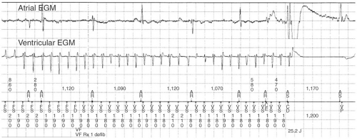 FIGURE 16-3. Implantable cardioverter defibrillator (ICD) electrograms from a dual chamber ICD demonstrating a rapid ventricular tachyarrhythmia (180 msec). The atrial channel shows atrial activity which is dissociated from the ventricular arrhythmia. The rapid rate of the tachycardia falls into a zone which is programmed to deliver a shock (25 J) and restores sinus rhythm. EGM, electrogram; AR, atrial even in refractory period; AS, atrial sensed event; FS, ventricular fibrillation sensed event; FD, ventricular fibrillation detected; VS, ventricular sensed event; CE, capacitor charged end; CD, charge delivered; VP, ventricular paced beat. (Marker Channel Abbreviations for Medtronic [slightly different for other vendors].) |
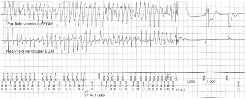 FIGURE 16-4. Implantable cardioverter defibrillator (ICD) electrograms from a dual chamber ICD. Ventricular fibrillation (VF) is sensed on the ventricular channel (near field) as well as the atrial channel (far field). EGM, electrogram; FS, ventricular fibrillation sensed event; VS, ventricular sensed event; FD, ventricular fibrillation detected; CE, capacitor charge end; CD, charge delivered; VP, ventricular paced beat; BV, biventricular paced beat. (Marker Channel Abbreviations for Medtronic [slightly different for other vendors].) |
ATP, when successful, allows the immediate delivery of therapy without the delay of capacitor charging as well as the avoidance of painful shocks. The ICD is usually programmed to deliver ATP as initial therapy in a tachycardia zone where one might expect VT to be readily discriminated from a supraventricular rhythm, but not so fast as to cause syncope. ATP is usually only effective in terminating VT due to reentry as it works by delivering multiple extra stimuli at a rate faster than the tachycardia cycle length (TCL). Once the extrastimuli enters the excitable gap of the reentrant circuit, it resets the circuit and terminates the circuit when the stimulus simultaneously blocks in the orthodromic direction and conducts antegradely in the circuit, colliding with the head of the preceding wavefront and abolishing the circuit. There are a variety of pacing algorithms used in ATP which are as follows:
Burst pacing comprises a set of extrastimuli (usually 8 to 10) at a certain percentage of the TCL, usually between 81% to 94% of the arrhythmia cycle length. If one burst fails to convert the VT, subsequent bursts can be programmed to have shorter cycle lengths.
Ramp pacing is similar except that the cycle length of each extrastimuli is decremented within each beat of the ATP cycle. This is a more aggressive pacing regimen that may terminate certain VTs but has increased risk of converting a regular tachycardia into polymorphic VT or VF.
ATP can painlessly terminate VT in 70% to 75% of cases. However, ATP is not stand-alone therapy as it can be proarrhythmic in 30% of cases by accelerating the clinical VT into a faster VT or VF. Consequently, it is essential that high output shocks be programmed as subsequent therapy in case this should happen.
ICDs can deliver shocks with a programmable amount of energy. Lower-energy cardioverting shocks, usually 5 to 20 J, can be delivered more quickly because of the linear relationship between shock energy and charge time, but risk accelerating the tachycardia do not deliver enough energy to convert the rhythm. The highest output devices are currently able to deliver up to 35 to 40 J, which is sufficient energy to terminate most tachyarrhythmias (see Table 16-2). In the rare circumstance that a high-output device is tested and is not able to provide a safety margin of 10 J over the DFT, additional leads such as a subcutaneous lead along the lateral and posterior chest wall must be added to the system (Fig. 16-1).
TABLE 16-2 Typical Implantable Cardioverter Defibrillator (ICD) Therapy Programming
| VT Zone | VF Zone | |
| VT, ventricular tachycardia; VF, ventricular fibrillation; ATP, antitachycardia pacing. | ||
| Heart rate | 170–200 bpm | >200 bpm |
| Cycle length | 300–350 msec | <300 msec |
| Detection | 18/24 intervals | 18/24 intervals |
| Therapy 1 | ATP (burst pacing) | 35 J |
| Therapy 2 | 25 J | 35 J |
| Therapy 3 | 35 J | 35 J |
| Therapy 4 | 35 J | 35 J |
| Therapy 5 | 35 J | 35 J |
Ventricular rate is the primary measure that determines the presence of ventricular arrhythmia; however, this alone can lead to inappropriate therapy for sinus tachycardia or supraventricular tachycardias (SVTs) with a ventricular response in the predetermined tachycardia zone. In order to minimize inappropriate therapies, ICDs have a number of methods to discriminate between VT and SVT (see Fig. 16-5). Sudden onset of the tachycardia, variability of the P-R interval, and stability of R-R intervals all favor VT. As well, many current models compare the morphology of the baseline electrogram with the ventricular electrogram during the tachycardia to discriminate between SVT and VT. This is most effective using a wide field electrogram such as from the RV-tip to the can. Abnormally rapid sensed activity in the atrial or ventricular
channel can represent damage to the lead such as lead fracture and can be misinterpreted by the device as VF resulting in device discharge (see Fig. 16-6).
channel can represent damage to the lead such as lead fracture and can be misinterpreted by the device as VF resulting in device discharge (see Fig. 16-6).
Stay updated, free articles. Join our Telegram channel

Full access? Get Clinical Tree


