Chapter 15 Catheter-Based Peripheral Angiography
Imaging Equipment
There are many radiographic equipment vendors and many different room layout schemes suitable for performing peripheral vascular angiography. However, if both cardiac and noncardiac types of peripheral vascular angiography are to be performed in the same room, equipment options become much more limited. One angiographic suite designed to perform both coronary and peripheral vascular angiography is a dual-plane system (Fig. 15-1). A dual-plane system encompasses a layout with two independent C-arm image intensifiers operated by a single x-ray generator and one computer. A dual-plane system is not synonymous with a biplane system, which is the simultaneous operation of an anteroposterior (AP) and lateral (LAT) image acquisition system. In a dual-plane system, the cardiac C-arm is a three-mode flat-panel image intensifier, and the noncardiac C-arm should be as large as possible, usually a 15- or 16-inch flat-panel image intensifier. For peripheral vascular imaging, particularly bilateral lower-extremity runoff angiography, an image intensifier smaller than 15 inches may not be able to include both legs in the same field. The noncardiac C-arm must be capable of head-to-toe digital imaging.
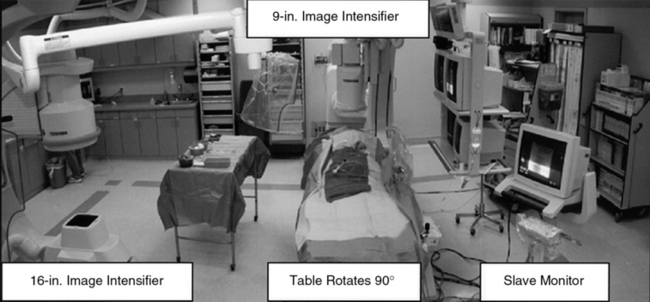
Figure 15-1 Dual-plane catheterization laboratory.
Note two C-arm image intensifiers (9- and 16-inch), with catheterization table able to rotate 90°.
Radiographic Contrast
Alternatives to iodine-based radiographic contrast include carbon dioxide (CO2) and gadolinium (gadopentetate dimeglumine).1,2 To minimize the risk of distal embolization and stroke, it is recommended that CO2 not be used for angiograms above the diaphragm.3 Gadolinium, traditionally used with magnetic resonance imaging (MRI), is relatively nontoxic in patients with adequate renal function at a recommended dose not exceeding 0.4 mmol/kg.4
Obtaining Vascular Access
Vascular access for noncardiac diagnostic angiography is most commonly achieved at the common femoral artery (CFA), with alternative upper-extremity sites at the radial, brachial, or axillary artery.5 The most common complications of angiographic procedures occur at vascular access sites.
A thorough understanding of the relationship of the CFA to anatomical landmarks is necessary to ensure safe CFA puncture (Fig. 15-2). The femoral artery and vein lie below the inguinal ligament, which is a band of dense fibrous tissue connecting the anterior superior iliac spine to the pubic tubercle. The inguinal skin crease, which is variable in location, is shown as a dotted line in the figure. Current recommendations are to use fluoroscopic guidance to image the femoral head to guide CFA puncture.6
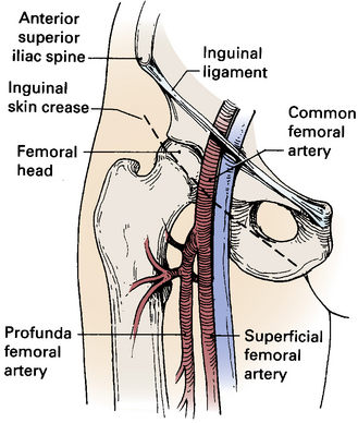
The most important landmark for femoral access is the head of the femur. In a morphological study using CT images, there was not a single case in which a puncture would have passed cranial to the inguinal ligament or caudal to the femoral artery bifurcation if the CFA were entered at the level of the center of the femoral head.7 Caudal to the femoral head, the CFA is encased in the femoral sheath and bifurcates into the superficial femoral artery (SFA) medially and the deep femoral artery (DFA) laterally. With these anatomical observations in mind, the importance of osseous support and entry of the needle into the CFA at the center of the femoral head is obvious.
Complications of CFA puncture are most commonly related to arterial entry that is either too high or too low. When the puncture is too high, a retroperitoneal hemorrhage may occur.8 Presence of loose connective tissue in the retroperitoneal space can lead to large hematomas. Lack of osseous support and presence of a tense inguinal ligament at the arterial puncture site make manual compression difficult. Low punctures may be complicated by formation of arteriovenous fistulas (AVFs), false aneurysms, and hematomas.
Abdominal Aortography and Lower-Extremity Runoff
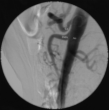
For abdominal aortography, vascular access with a 4 F to 6 F catheter is obtained in the CFA, although brachial or radial access may also be used. The angiographic catheter (e.g., pigtail, tennis racquet, omni flush) is positioned in the abdominal aorta such that the tip of the catheter reaches the level of the last rib. A power injector is used to deliver 20 to 30 mL of contrast at 15 mL/sec for digital subtraction (Fig. 15-3). Either biplane angiography may be obtained or, if needed, two separate angiograms with single-plane systems. Three visceral (mesenteric) arterial branches, the celiac trunk, superior mesenteric artery (SMA), and inferior mesenteric artery (IMA), arise from the anterior surface of the abdominal aorta (Fig. 15-4). The renal arteries originate from the lateral aspect of the abdominal aorta at the level of L1 to L2. The AP projection allows visualization of the aorta, renal arteries, and iliac artery bifurcation, whereas the LAT view demonstrates the origin of the celiac trunk and mesenteric arteries. Commonly in the AP view, the proximal portion of the SMA obscures the origin of the right renal artery. When this occurs, selective angiography of the renal artery may be required to visualize the origin of this vessel.
Selective Renal Angiography
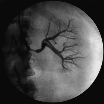
Selective renal angiography is indicated to identify suspected renovascular disease. Selective renal artery engagement allows measurement of pressure gradients, particularly if ostial lesions are suspected. When measuring pressure gradients across lesions, it is important to use the smallest catheter possible (i.e., ≤4 F) to avoid creating an artificial gradient. The 0.014-inch pressure wire (RADI) is the optimal method of pressure gradient measurement. Usually, selective renal angiography is performed with 4 F to 6 F diagnostic catheters (Fig. 15-5) and a 9-inch image intensifier. Selective renal angiography is performed using hand injections with shallow oblique angulations to optimize visualization of the renal ostia (Figs. 15-6 and 15-7). Caudal or cranial angulation (15° to 20°) may occasionally be necessary for better visualization of some ostial lesions. An optimal image will reveal the ostial portion of the renal artery and distal branches at the cortex of the kidney.
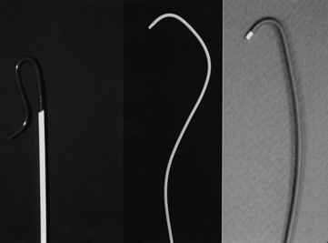
Figure 15-5 Selective renal angiographic catheters.
Left, Sos. Middle, Cobra. Right, Internal mammary artery (IMA) catheter.
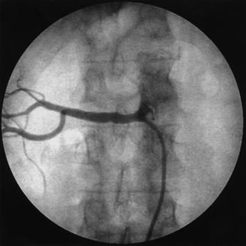
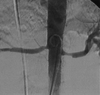
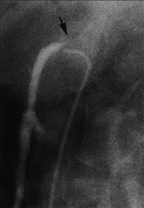
Figure 15-6 Femoral access.
Internal mammary artery (IMA) catheter selectively engaged in right renal artery.
Selective Mesenteric Angiography
As is the case for the renal arteries, nonselective aortography (AP and LAT) generally precedes selective angiography of the mesenteric arteries. Once the origin of the mesenteric vessel has been identified, selective angiography may be carried out in the LAT and oblique views using 4 F to 6 F catheters (Fig. 15-8). The celiac trunk, SMA, and IMA arteries arise from the anterior surface of the aorta. There commonly are collaterals between the mesenteric vessels, and it is uncommon for stenosis or occlusion of a single branch to cause clinical symptoms.
Stay updated, free articles. Join our Telegram channel

Full access? Get Clinical Tree


