CHAPTER
13
Cardiac Implantable Electronic Devices
PERMANENT PACEMAKERS
Cardiac implantable electronic devices (CIEDs) sense intrinsic cardiac electric potentials and, if too infrequent, transmit electrical impulses to the heart to stimulate cardiac contraction.
○ Sensing: Sensing is the ability of the pacemaker to appreciate an intrinsic electrical signal. The response to sensing can be:
▪ Inhibition: The pacemaker stimulus is suppressed due to a spontaneous intrinsic event sensed before the end of the sensing (alert) period.
▪ Triggering: The pacemaker stimulus is generated due to a spontaneous intrinsic event sensed before the end of the sensing (alert) period.
○ Capture: The ability of a pacemaker to trigger a cardiac depolarization and resultant mechanical myocardial contraction (atrial or ventricular).
▪ Pacemaker output pulses can be understood by considering Ohms law: Current = voltage / resistance.
• Voltage (V): The force moving current (measured in volts)
• Current (I): The volume of flow of electricity (measured in amperes)
• Impedance (R): Resistance to flow (in the circuit and patient; measured in ohms)
CIED NOMENCLATURE (NBG Code)
Table 13.1 Standard CIED Nomenclature
| First Position | Second Position | Third Position | Fourth Position | Fifth Position |
Chamber Paced | Chamber Sensed | Response to Sensing | Rate Modulation | Multisite Pacing |
A | A | T | O | O |
V | V | I | R | A |
D | D | D | V | |
O | O | D |
NBG: NASPE/BPEG Generic.
○The first letter indicates the chamber(s) paced.
▪ A: Atrial
▪ V: Ventricular
▪ D: Dual-chamber (atrial and ventricular)
○The second letter indicates the chamber in which electrical activity is sensed.
▪ A, V, or D
▪ O is used when the pacemaker discharge is not dependent on sensing.
○The third letter refers to the response to a sensed electric signal.
▪ T: Triggering of pacing function
▪ I: Inhibition of pacing function
▪ D: Dual response (i.e., any spontaneous atrial or ventricular activity will inhibit that chamber’s pacing function but lone atrial activity will trigger a paced ventricular response)
▪ O: No response to an underlying electric signal
○The fourth letter represents rate modulation.
▪ R: Rate-response (“physiologic”) pacing
▪ O: No programmability or rate modulation
○The fifth letter represents multisite pacing
▪ A, V, or D
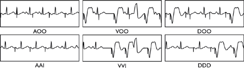
Programming Modes
○AOO or VOO: Paces regardless of intrinsic activity (i.e. no sensing or inhibition)
○AAI: Pacing and sensing in the atrium only (reserved for pure SA node disease)
○VVI: Pacing and sensing in the ventricle only, usually used with permanent atrial fibrillation (AF)
○VDD: Usually single lead device that senses atria and paces ventricle
○DDD: Dual chamber (atrial and ventricular) sensing and pacing
○AAT or VVT: Diagnostic (tests sensing thresholds or etiology of inhibitory signal–lead/muscle)
A Basic CIED System
Pulse Generator
○The pulse generator is placed subcutaneous (pre-pectoral) or submuscular in the chest wall.
○Consists of:
▪ Casing (a.k.a., “can”): Titanium (biocompatible, strong, and lightweight)
▪ Connector: An epoxy “header” containing the lead connector ports.
▪ Components (sensing, timing, and output circuits)
• Diodes: Keep current going the right direction
• Resistors: Impede flow in an effort to channel the current
• Crystal oscillator: The “time clock” of the pulse generator
• Microchips: Memory and “intelligence” functions
▪ Battery (usually lithium iodide): The largest component inside the pulse generator
Pacing Leads
○Endocardial leads are inserted transvenously to the atrium, RV, and/or the coronary sinus (CS).
○Epicardial leads can be inserted via thoracotomy and are fixed to the exterior of the heart.
○Endocardial leads are implanted into the myocardium via:
▪ Active fixation (distal screw)
• Advantages
▫ Easy fixation, with the ability to reposition
▫ Lower rate of dislodgement
▫ Chronic removability
• Disadvantages
▫ More expensive
▫ More complicated implantation procedure
▪ Passive fixation (distal fins or tines designed to snag/entangle the trabeculae)
• Advantages
▫ Less expensive
▫ Minimal trauma to patient
▫ Potentially lower thresholds
• Disadvantages
▫ Higher rate of acute dislodgement
▫ It is more difficult to remove a chronic lead.
○Pacing leads can be:
▪ Bipolar: Two conductor coils (electrodes) on the distal portion of the lead, and separated by 2–3 cm of insulation on the distal portion of the lead.
• The stimulating cathode (negative pole) is the distal electrode (distal tip).
• The receiving anode (positive pole) is the proximal electrode (proximal ring).
• Advantages
▫ Less oversensing (far field, myopotentials, electromagnetic interference)
▫ No pocket (pectoral muscle) stimulation
▫ May be programmed to a unipolar configuration
• Disadvantages
▫ Larger diameter with a stiffer lead body
▪ Unipolar: Single conductor coil and electrode tip
• The stimulating cathode (negative pole) is intracardiac (distal tip).
• The receiving anode (positive pole) is extracardiac (the pulse generator).
• Advantages
▫ It has a smaller diameter lead.
▫ Theoretically it is more reliable (single coil within the lead).
▫ There is a larger paced electrogram (EGM) amplitude due to larger field.
• Disadvantages
▫ It is limited to a unipolar configuration.
▫ It has a tendency to oversense (far field, myopotentials, electromagnetic interference).
▫ Pacing may result in pocket stimulation.
▫ It cannot be used with implantable cardioverter-defibrillators (ICDs).
CARDIAC IMPLANTABLE ELECTRONIC DEVICES (CIEDs) TIMING CYCLES
○General terminology
▪ Refractory period (300 ms): Interval during which the CIED does not respond to intrinsic signals
• This keeps the pacemaker from resetting the timing cycle with inappropriate signals.
• Absolute refractory period “Blanking” (30–50 ms)
▫ The CIED does not “see” intrinsic signals.
• Relative refractory period
▫ The CIED “sees” and counts intrinsic events but does not respond to them.
• This is the time after the refractory period that sensor is open and looking for signals.
▪ Lower rate limit (LRL): The slowest rate of pacemaker stimulation.
• This is analogous to the pacing interval, which is the time period in milliseconds between two consecutive paced events in the same chamber without an intervening sensed event.
▪ Upper rate limit (URL)
• This is the fastest rate the pacemaker will stimulate the heart (i.e. the maximum tracking rate if a dual chamber device; or the maximum sensor rate if rate response is turned on).
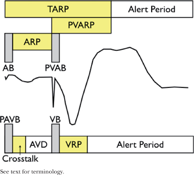
○Atrial channel
▪ AV delay (AVD)
• Time from native/paced atrial event to the subsequent ventricular impulse (native or paced)
▪ Atrial blanking period (ABP) and post-ventricular atrial blanking period (PVABP; a.k.a. far-field blanking)
• Period of blanking post intrinsic or paced atrial impulse (ABP) or ventricular pacing (PVABP)
• Prevents the atrial channel from oversensing the paced impulses in atria/ventricle, respectively
▪ Atrial refractory period (ARP) and and post-ventricular atrial refractory period (PVARP)
• Time that the atrial channel is refractory
• Initiated by intrinsic or paced atrial impulse (ARP) or ventricular pacing (PVARP)
• Prevents the pacemaker from restarting the timing cycle to inappropriate signals
▫ ARP: Device is able to count intrinsic atrial impulses and extrinsic noise
▫ PVARP: prevents the device from tracking ventricular depolarization and retrograde P waves.
▪ Total atrial refractory period (TARP)
• Sum of ABP + ARP (AV Delay [AVD]) and post-ventricular atrial refractory period (PVARP)
▫ Atrial sensed events during TARP do not affect the timing cycle but will trigger the mode-switch.
• The length of TARP will limit the URL (maximum tracking rate or maximum sensor rate).
▫ If TARP is ≥ URL, there will be 2:1 behavior (abruptly “hitting the wall”).
▫ If TARP is < URL, then Wenckebach phenomena will be observed (“Wenckebach window”).
▪ Atrial alert period
• This is the time after the refractory period when the atrial sensor is looking for stimuli.
○Ventricular channel
▪ Ventricular blanking period (VBP) and post-atrial ventricular blanking period (PAVBP)
• This is the period of blanking post-intrinsic or -paced ventricular impulse (VBP) or atrial pacing (PAVBP).
• It prevents the ventricular channel from sensing the paced impulses.
▪ Ventricular triggering period (“cross-talk sensing window”)
• When a ventricular sensed event occurs during this period (typically 100–120 ms), it would trigger “safety pacing” (ventricular pacing at an interval that is shorter than the AVD).
▪ Ventricular refractory period (VRP)
• This is the time period that ventricular channel is refractory.
• It is initiated by an intrinsic or paced ventricular impulse.
• It prevents the pacemaker from restarting the timing cycle to inappropriate signals.
▪ Ventricular alert period
• It is the period after the VRP where the ventricular sensor is looking for stimuli.
○Timing cycles
▪ VV timing (pacer keeps constant VV interval) is the most common.
▪ AA timing (pacer keeps constant AA interval) is also used.
Other Pacemaker Functions
○Rate-response/rate-adaptive pacing
▪ A sensor within the pacemaker increases and decreases the pacing rate based on “physiologic need.”
• Essentially, this sensor acts as a surrogate for normal SN variability.
• The minimum and maximum heart rate, and “aggressiveness” can be programmed.
• This function is useful for patients with chronotropic incompetence.
▪ Types of sensors:
• Vibration sensors react to vibration using a piezoelectric crystal.
▫ Pro: They have a quick response, need no special lead, provide easy programming, and are self-powered.
▫ Con: The sensor is not specific to exercise and is easily influenced by external vibration (i.e., tremor, bumpy car rides); the response is not proportional to the work load, and they are hard to optimize.
• The accelerometer reacts to forward/backward activity at specific frequencies.
▫ Pro: As per vibration, it is less susceptible to external influences; it is proportional to the workload.
▫ Con: It can be fooled by certain motions (rocking chair), and it is not sensitive to external demand.
• Minute ventilation sensors react to transthoracic impedance (resistance across the chest).
▫ Pro: They are slow to respond, sensitive to workload, and immune to the environment.
▫ Con: They are unable to use a unipolar lead; arm motion/speech influences the sensor.
• Evoked response sensors react to a decrease in the measured QRS depolarization area.
▫ Note: These sensors only work when the device is pacing.
• QT interval sensors react to a decrease in QT interval (measured from pacing spike to evoked T wave).
▫ Note: They only work when the device is pacing.
•Closed-loop sensors assess cardiac inotropy via the variations of intracardiac impedance on a beat-to-beat basis during the systolic phase of the cardiac cycle at the apex of the right ventricle.
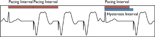
▪ The pacemaker allows the rate to fall below the programmed LRL following the sensing of an intrinsic beat in the alert period (kicks in at a programmable rate lower than LRL).
• It is used to encourage native cardiac activity and prolong battery life.
▪ Search/scan hysteresis temporarily decreases the rate to allow intrinsic cardiac activity. This can occur with:
• AV conduction (↑ AVD to allow native conduction) or ventricular activity (rate < base rate)
• Reverse hysteresis (↓ the AVD in order to speed conduction in response to a short pulse rate)
▫ Essentially, this works to force ventricular pacing; it is only useful with cardiac resynchronization therapy (CRT) devices
○Rate-adaptive AV delay
▪The AVD can shorten from a programmed baseline to a programmed minimum AVD as the atrial rate increases (mimics normal physiology).
• Allows atrial tracking at faster rates because of a shorter TARP (AVD + PVARP).
▪ It is performed through either linear or stepwise shortening of the AVD.
○Mode switching
▪ Rapid atrial rates sensed by the pacemaker induce a switch from dual- to single-chamber pacing to avoid tracking of atrial arrhythmia and pacing the ventricle at unnecessarily high rates.
○Active capture control/autocapture
▪ The pacemaker periodically starts at maximum amplitude and works down to the minimum effective capture threshold in order to minimize device output.
○Rate fading
▪ This smooths the heart rate to prevent abrupt change (exercise-induced ↓ heart rate, mode-switching).
IMPLANTABLE CARDIOVERTER-DEFIBRILLATOR (ICD)
○An ICD is a specialized device designed to directly treat a cardiac tachyarrhythmia.
○The basic system does not fundamentally differ from a pacing system, except that:
▪ The generator has a larger volume (to house the high-voltage power supply and a shock capacitor).
▪ The RV pacing lead has a larger diameter owing to the defibrillation function.
▪ Anti-tachycardia pacing (ATP) results in the device delivering a preset number of rapid pulses in succession in an attempt to terminate the arrhythmia.
• Types of ATP
▫ Burst: RV pacing is at a fixed rate. Usually, it is set as a percent of the ventricular tachycardia cycle length (CL).
▫ Ramp: The RV pacing rate progressively increases within the drive train.
▫ Scan: This provides burst RV pacing at progressively faster rates. The rate is altered between drive trains, resulting in the next burst being faster than the last.
▫ Ramp–scan: This is a combination of the above.
• Programmable
▫ Coupling interval: Timing of the first pulse is after the VT beat.
▫ Cycle length: Generally, it is set at 81%–88% of the tachyarrhythmia cycle length.
▫ Burst length: It is the number of beats in the drive train (usually 8).
• Outcomes
▫ Generally, there is a >90% success for arrhythmia termination (70% for fast VT).
▫ This improves the quality of life and potentially survival (when compared to ICD shocks).
▪ If unsuccessful, the device will perform a cardioversion or defibrillation, a low- or high-voltage, biphasic shock between the defibrillation coil and generator
• Programmable
▫ Energy: In Joules (voltage × current × time)
▫ Waveform: Monophasic (shock is delivered to the heart from one vector) or biphasic (shock is delivered via two vectors; more effective).
▫ Vector: RV Coil (B) to can (A) and SVC coil (X); RV coil to can; RV coil to SVC coil
▫ Direction: Normal = Coil to can (B to AX); reversed = Can to coil (AX to B)
○It is important to note that the “ventricular tachycardia/ventricular fibrillation” (VT/VF) detection is based on the heart rate sensed from the RV electrode.
▪ If a set duration of tachycardia is exceeded, then the arrhythmia is “detected.”
• Thereafter, discriminators can be used to differentiate ventricular from supraventricular origin (note: descriminators are only applied in the VT zone and cannot be programmed in the VF zone).
• However, in the absence of discriminators, the rate and duration of tachycardia define the arrhythmia “zone” and elicit programmed therapies. As such, fast SVT may result in therapies being delivered due to the ventricular rate exceeding the predefined trigger.
○Up to three ventricular rate-detection zones can be programmed to allow delivery of different ICD therapies depending on the tachyarrhythmia rate.
▪ The slow VT zone is usually set between 170 and 188–200 bpm.
• In primary prevention, this may be set to monitor only (no therapies delivered) or to include a variable number of anti-tachycardia pacing (ATP) therapies prior to cardioversion or DC shock.
▫ In general, ATP therapy is more effective for slower VTs.
▪ The VF zone is usually set for rates faster than 222–250 bpm and may include ATP during charging.
○Redetection: After the ICD delivers therapy, it needs to check the rhythm again to determine if the arrhythmia has terminated.
▪ The ICD searches for sinus rhythm (which is defined by the ICD only by heart rate).
▪ If the ICD cannot determine a return to sinus rhythm, it concludes the arrhythmia is ongoing and delivers more therapy.
ICD Therapies
○Detection, assessment, and treatment of tachyarrhythmia is progressive and depends on several steps.
Step 1. Sensing
○The most important step in the detection of tachyarrhythmia is the ability of the device to sense it.
▪ Tachyarrhythmia is fundamentally different to bradyarrhythmia detection, needing to differentiate signals over a wide range of amplitudes (e.g., a sinus rhythm R wave 10 mV, but a VF R wave of VF 0.2 mV) while avoiding oversensing other signals (e.g., T wave).
▪ While the EGM amplitude may be adequate in sinus rhythm, there may be variable sensitivity during tachycardia due to rapid changes in the EGM amplitude.
▪ This may result in some signals being underdetected (“drop-out”).
▪ If enough are underdetected, then the rate trigger or counters may not meet criteria to diagnose a tachyarrhythmia, and thus therapy would not be delivered.
○In general, ICDs automatically adjust sensitivity relative to the signal amplitude, or automatically adjust the signal amplitude (gain) relative to the sensitivity.
▪ Automatic/adaptive sensing threshold adjustment starts with a low baseline sensitivity (typically 0.3 mV), which increases to a percentage of the R-wave amplitude (typically 50% to 80%).
• The sensitivity then decays linearly, exponentially, or with an initial constant then linear.
▪ Band pass frequency: Narrow the frequency to remove the sensing of noise.
▪ Dynamic noise algorithm can raise the sensing to stay above noise.
Step 2. Detection Criteria
○ Rate: The first step in determining if an arrhythmia is present is merely determining the frequency of the tachycardia. Based on the rate, a zone (e.g., VT or VF) is determined for subsequent therapies.
○ Duration: The second criterion for detection is the duration of tachycardia. This is used as a surrogate to determine whether the arrhythmia is sustained or non-sustained.
▪ It is programmed as a series of counters, e.g., 18/24 beats of tachycardia > the rate detection threshold.
Step 3. Algorithms for Discrimination of SVT from VT
○Note: Descriminators do not apply in the VF zone.
○SVT detection (“Rate Branch”)
▪ The atrial and ventricular rates are compared.
• If the rates are equal (V = A) or the atrial rate is greater than the ventricular rate (A > V), then further discriminators are applied.
• If the ventricular rate is greater than the atrial rate (V > A), then therapy is delivered.
○Therapy inhibitors
▪ Morphology: The device composes templates of EGM morphology in baseline (e.g., normal sinus) rhythm.
• Using vector timing and correlation, the device compares these baseline templates to tachycardia with the expectation that they will differ significantly from those registered during a ventricular arrhythmia: e.g., SVT looks like sinus (>94% correlation) or VT doesn’t look like sinus (<94% correlation).
• These templates are especially useful in single-chamber devices due to the lack of atrial lead.
• These templates should not be used in patients with bundle branch block (BBB) or rate-dependent EGM changes.
▪ Sudden onset: This compares the RR interval at tachycardia onset to the average RR interval in the preceding beats – nominal deemed sudden if the difference is greater than 100 ms.
▪ This helps differentiate sinus tachcyardia (gradual onset) from VT (sudden onset)
• Discriminator function
▫ If the measured delta is greater than the programmed delta, therapy is not inhibited (i.e., VT).
▫ If the measured delta is less than the programmed delta, therapy is inhibited (i.e., SVT).
• Programming:
▫ It is possible to inhibit therapy by adjusting the delta to a smaller value, which makes the device more sensitive to detect VT; e.g., a smaller change or jump in arrhythmia onset is required to qualify as VT.
• Limitations of this discriminator:
▫ It may fail if VT occurs during sinus or supraventricular tachycardia. That leads to a smaller decrease in the RR interval compared to the preceding beats.
▫ It may fail if VT accelerates gradually into (from below) detection zone. This is particularly challenging when VT crosses in and out of detection zones.
▪ Rate/interval stability: The device examines the RR intervals between tachycardia beats and determines whether the tachycardia is regular or irregular based on programmed criteria.
• This helps differentiate AF (irregular/unstable cycle length) from VT (regular/stable cycle).
• Discriminator function
▫ During tachyarrhythmia, the delta between the second-longest and the second-shortest intervals in the interval stability window (nominal 12) is measured.
▫ If the measured delta is less than the programmed stability delta (nominal 80 ms), therapy is not inhibited (e.g., deemed stable and therefore VT).
• Programming: Adjusting the delta to a smaller value makes the device less sensitive to detecting VT (smaller variations in rate required to qualify as AF).
• Limitations of this discriminator: It may fail if irregular VT or pseudo-regular AF exists.
▪A-V association: Assesses the AV ratio by evaluating the number and timing of P waves between R waves.
• The AV association and pattern/timing is used to define AV versus VA conduction, e.g., VT with retrograde conduction.
• Used in conjunction with stability, onset, and morphology in dual-chamber devices.
• Discriminator function
▫ During tachycardia, the delta between the second-longest and second-shortest AV intervals in the stability window is measured (nominal 12).
▫ If the measured delta is less than the programmed AVA delta (nominal 60 ms), an association between A and V events is determined and SVT is diagnosed.
▫ If the measured delta is greater than the programmed AVA delta (nominal 60 ms), dissociation between A and V events is determined and VT is confirmed.
○Inhibitor override
▪ Sustained rate duration delivers therapy after a programmable time interval even if the episode has been classified as SVT.
• This aims to prevent VT therapies from being are erroneously inhibited by discriminators.
• Limitations: It may result in inappropriate shocks for sustained SVT.
○Therapy accelerator
▪ Shock if unstable: Therapy is delivered if the device determines the VT is polymorphic in nature.
COMPLICATIONS OF DEVICES
Early
○Venous access (<1%)
▪ Pneumothorax, hemothorax, air embolism
○Lead
▪ Myocardial or cardiac perforation (<1%)
▪ Malposition or inability to place (inability to obtain satisfactory thresholds, phrenic stimulation)
▪ Dislodgment (1%–5%; RV < RA < LV/CS); usually <3 days but may occur up to 3 months post procedure
▪ Hematoma (<5%; ↑ with anticoagulation or dual antiplatelet therapy)
▪ Infection (1%–3%): These include superficial, wound dehiscence, deep (pocket), or systemic (endocarditis).
▪ Pain: Suspect an infection if it occurs remote from the implant or improves and then recurs.
○Generator
▪ Loose set screw
Delayed
○Venous Access
▪ Venous thrombosis, or SVC syndrome (0.5%)
○Lead
▪ Exit block
▪
Stay updated, free articles. Join our Telegram channel

Full access? Get Clinical Tree


