CHAPTER
2
Electrophysiology Study and Maneuvers
THE ELECTROPHYSIOLOGY STUDY
Indications
○Evaluation of sinus node function in patients in whom sinus node dysfunction is suspected (but not confirmed) as the cause of symptoms
○Evaluation of symptomatic patients in whom His-Purkinje block is suspected as a cause of symptoms
○Evaluation of narrow QRS complex tachyarrhythmias
▪ Patients with frequent or poorly tolerated episodes who do not adequately respond to drug therapy
▪ Patients who prefer catheter ablation to pharmacological therapy
○Evaluation of patients with wide QRS tachycardia in whom the diagnosis is unclear after clinical analysis, and for whom the correct diagnosis is essential for patient care
○Assessment of patients with Wolff-Parkinson-White syndrome
▪ Patients being evaluated for catheter ablation or surgical ablation of an accessory pathway (AP)
▪ Patients with ventricular pre-excitation with unexplained syncope or who have survived cardiac arrest
○Investigation of unexplained syncope, including suspected structural heart disease and syncope that remains unexplained after evaluation
○Assessment of patients surviving cardiac arrest without evidence of acute myocardial infarction (MI) or >48 h after the acute phase
○Assessment of patients with palpitations and inappropriately rapid pulse in whom the cause is not documented
Complications
○The incidence and type of complication depends on the procedure being performed (see Table 2.1).
▪ Atrial tachycardia (AT) or atrial flutter has a complication rate of about 4%–5%.
▪ Ablation of the atrioventricular (AV) junction has a complication rate of about 2%–3%.
▪ Modification of the AV junction for atrioventricular nodal reentrant tachycardia (AVNRT) has a complication rate of about 3%–4%.
▪ Ablation of an AP has a complication rate of about 2%–4%.
▪ Ablation of ventricular tachycardia (VT) has a complication rate of about 5%–8%.
Table 2.1 Complications Associated with Various Diagnostic and Therapeutic Procedures
| Complication | Diagnostic | Ablation |
Death | <0.1% | 0.3% |
Access site complication | 0.2% | 0.6% |
Embolism (systemic or cerebral) | <0.1% | 0.2%–0.5% |
Myocardial ischemia or infarction | <0.1% | 0.1%–0.2% |
AV block necessitating pacemaker | <0.1% | 0.5%–2.0% |
Pericardial effusion | <0.1% | 0.3%–2.0% |
Tamponade | <0.1% | 0.2%–0.7% |
Pericarditis/chest pain | <0.1% | <1.0% |
Venous thrombosis | 0.5%–1% | 0.5%–1% |
Major bleeding | <0.1% | 0.2%–0.7% |
Pacemaker lead dislodgment | <1% | <1% |
Pneumothorax | 0.1% | 0.1% |
Total | 1% | 3% |
STANDARD CATHETER PLACEMENT
High Right Atrium
○Catheters used include Josephson or Cournand shape.
▪ Quadripolar catheters are used for simultaneous stimulation and recording.
○Preferred position is high posterolateral wall at the junction of the superior vena cava (SVC) as this site approximates the sinoatrial (SA) node exit site.
▪ Right atrial appendage (anterior) may be used if it is difficult to place.
▪ Technique: In the anteroposterior projection, advance the catheter to the HRA and torque catheter posteriorly.
○While recording, keep in mind:
▪ The EGM corresponds to the depolarization wavefront arriving at the atrial cells of the superior RA.
▪ The timing of the EGM is close to the onset of the P wave on the surface ECG.
Right Ventricle
○Catheters used include Josephson or Cournand shape.
▪ Catheters are quadripolar for simultaneous stimulation and recording, or bipolar (capture inferred from ECG).
○Preferred position is in the right ventricular apex (RVa).
▪ Right ventriclar outflow tract (RVOT) is used in difficult cases or if dual-site pacing is required.
▪ Technique: In anteroposterior or RAO projection, advance catheter to RVa.
○While recording, keep in mind:
▪ EGM corresponds to the depolarization of the RV after the signal has exited the His-Purkinje.
▪ Timing of the EGM is close to the onset of the QRS on the surface ECG.
His Bundle Catheter
○Catheters used include CRD2, Josephson, or Cournand shape.
○Usual location is approximately 1–2 o’clock on the Tricuspid valve (TV) in LAO projection where there is a large His EGM.
▪ Technique: Position the catheter across the anterior-superior TV in anteroposterior or RAO projection, then gently withdraw the catheter with clockwise torque to assure septal contact.
○While recording, keep in mind:
▪ Atrial EGM corresponds to depolarization of the cells located in the low RA near the atrioventricular node (AVN).
▪ His EGM corresponds to depolarization of the proximal His-Purkinje after the EGM exits the AVN.
▪ Ventricular EGM corresponds to the depolarization of the ventricular cells adjacent to the node.
• The timing of the EGM is close to the surface QRS onset as the septum is one of the first areas activated.
○Caveats
▪ An inadequate atrial EGM results in:
• Underestimation of the HV interval due to the recording of a right bundle potential
• Misinterpretation of the position of the AVN and aortic root
Coronary Sinus
○Multipolar catheter (8–10 electrodes) is utilized to record the LA activation sequence.
○Positioning depends on which approach is used.
▪ Inferior approach
• The catheter is positioned across the TV and deflected inferiorly. It is then withdrawn with clockwise torque until equal atrial and ventricular EGMs are recorded. Once the coronary sinus (CS) ostium is engaged, release the deflection while continuing to apply clockwise torque to allow the tip to turn superiorly and follow the course of the vein.
• Position the catheter across the TV and withdraw towards the IVC while applying clockwise torque until equal atrial and ventricular EGMs are recorded.
▪ Difficulties in positioning the catheter may include:
• Failure to cannulate the CS ostium
• Failure to advance catheter distally in the CS due to a distal valve
• Recurrent catheter dislodgement; consider using a support sheath (SR0 or SL2) or switching to a superior approach
○While recording, keep in mind:
▪ Atrial EGM corresponds to the depolarization of the LA cells adjacent to the mitral annulus.
• As depolarization progresses from the sinoatrial node (SA Node) the activation pattern in the CS will be proximal to distal.
▪ Ventricular EGM corresponds to the depolarization of the LV cells adjacent to the mitral annulus.
▪ Caveats
• Partial introduction with the distal poles at the mid-CS position and the proximal poles outside the ostium can result in misclassification of midline activation as eccentric.
MEASUREMENT OF BASIC CONDUCTION INTERVALS
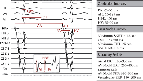
Cycle Length
○Cycle length (CL) is the length of time between each successive heartbeat as measured in milliseconds.
PA Interval (normal: 25–55 ms)
○PA interval is an estimation of intra-atrial conduction.
▪ It represents the time for activation to travel from the SA node region to the AVN region.
▪ The PA interval is measured from the earliest atrial activation in any channel (surface P wave or earliest atrial EGM) to the rapid deflection of the atrial EGM on the His bundle catheter.
AH Interval (normal: 55–125 ms)
○AH interval is an estimation of AVN conduction time.
▪ It represents the time for the impulse to travel from the low RA through the AVN to the His bundle.
▪ The AH interval is measured on the His bundle catheter between the earliest rapid atrial deflection (low RA depolarization) and the beginning of the His EGM.
▪ It can vary by up to 20 ms due to autonomic tone.
His Bundle EGM (HBE) Duration (normal: <30 ms)
○HBE is the time needed for activation of the His bundle.
▪ The HBE duration is measured from the beginning to the end of the HBE.
▪ Minor delay may cause a notching of the HBE, with significant delay causing a split HBE.
HV Interval (normal: 35–55 ms)
○The HV interval is the time needed for conduction from the His bundle through the His-Purkinje system to the ventricular myocardium.
▪ It is measured from the onset of the HBE to the earliest ventricular activation (surface QRS or V EGM).
PR Interval
○The PR interval is the summation of the PA interval, the AH interval, and the HV interval.
QRS Duration (normal: <120 ms)
○The QRS duration is the time needed for ventricular activation to occur.
QT Interval (normal: <440 ms in men or <460 ms in women)
○The QT interval is the time needed for ventricular activation and repolarization to occur.
REFRACTORY PERIODS
○After cardiac depolarization, the period of time during which it cannot be depolarized again is termed the refractory period (usually from phase 0 to late phase 3 of the cell’s action potential).
○With progressively shorter coupling intervals, three characteristic refractory periods are observed.

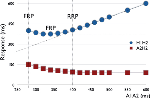
Relative Refractory Period (RRP): “Change”
○As the input coupling interval is steadily decreased, there is initially a steady relationship between the “input” (e.g., S1S2) and the solicited tissue response, or “output” (e.g., H1H2 or A2H2).
○With progressively shorter coupling intervals, the tissue response changes, whereby shorter output coupling intervals are still induced; however, the magnitude of effect is lessened.
○This point where the output interval begins to differ from the input is defined as the RRP.
○RRP is also known as the point at which latency or decremental conduction begins (i.e. if the impulse was delivered any later it would conduct normally).
▪ Decremental conduction: Progressively shorter coupling results in slower conduction velocity.
• Decremental conduction is seen with tissues dependent on “slow” inward calcium current for depolarization (e.g., AVN).
• Purkinje fibers are dependent on “fast” sodium channels resulting in nearly no decrement.
• Myocardium (atrial and ventricular) has minimal decremental properties.
▪ Latency is the delay between the extrastimulus and the EGM generated by the tissue.
• Latency is observed when the short-coupled extrastimulus impinges on the refractory period of the adjacent myocardium.
Functional Refractory Period (FRP): “Best”
○As the “input” coupling interval is progressively decreased, there is a change in the tissue response such that the “optimal” conduction interval is reached (i.e., shortest output coupling interval).
▪ Functionally, this is a quantitative measure of tissue output (conduction velocity and refractoriness).
• It defines the lower limit of the output that the tissue/structure can produce.
Effective Refractory Period (ERP): “Loss”
○Thereafter, shorter input coupling intervals result in a progressive “worsening” in tissue output down to the ERP.
○ERP is defined as the longest coupling interval for which an impulse fails to propagate through tissue (i.e., if the impulse were delivered any later, it would conduct).
▪ ERP occurs during the last third of phase 3 of the AP.
Assessment of Refractory Periods
Incremental Pacing
○Pacing is initiated at a rate slightly faster than the patient’s spontaneous rhythm.
▪ Pacing CL is decreased step-wise to the point of block or to a minimum cycle of 200–300 ms.
○Determine the following:
▪ The Wenckebach CL (WCL), which is the time when 1:1 conduction ceases.
▪ The presence/absence of retrograde atrial activation.
▪ The retrograde atrial activation sequence (concentric vs. eccentric).
▪ The site of block (AH or HV).
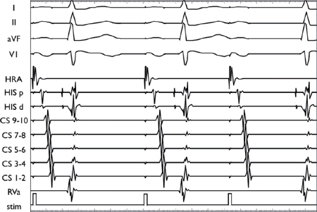
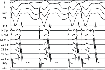
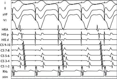
Decremental Conduction as a Result of Incremental Atrial Pacing
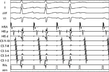
As the pacing CL is progressively decreased in the atria, the conduction decrements in the AVN before eventually blocking (second-to-last beat).
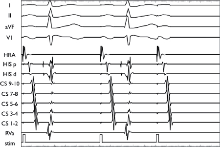
During ventricular pacing, there is no initial latency (a. V1V2 = S1S2). A delay is observed between the pacing stimulus (S) and the elicited EGM (V) as the paced beat (or extrastimulus) starts to impinge on the refractory period of the ventricular myocardium (b. Onset of latency: V1V2 > S1S2). Thereafter, a more marked latency is seen (c. V1V2 >> S1S2), followed by tissue refractoriness (d. No V2).
Extrastimulus
○Technique for inducing and assessing extrastimuli is as follows:
▪ A series of impulses at fixed CL (8-beat S1) is followed by the introduction of one or more extrastimuli at a fixed coupling interval (S2, S3, etc.)
▪ Typically, start with an 8-beat drive train (S1) at 600 ms with S2 at 580 ms.
▪ The coupling interval (S2) is reduced by 10–20 ms to 200 ms or refractoriness.
▪ Additional extrastimuli (S3, S4, etc.) can be introduced depending on the study protocol.
▪ Note: As shorter S1 CLs decrease, the refractory period in most tissue (except the AVN) the refractory period must be measured over at least 2 basic CLs.
• Usually repeated with an S1 of 400 ms (depending on the basal rate)
○Interpretation includes making the following assessments:
▪ Anterograde refractory periods
• AVN effective refractory period (AVNERP: Normal 250–400 ms)
• Atrial effective refractory period (AERP: Normal 180–330 ms)
▪ Retrograde refractory periods
• VA refractory period (retrograde AVNERP or VAERP)
• Ventricular refractory period (VERP: Normal 180–290 ms)
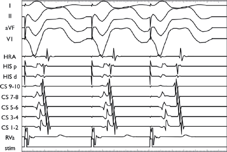
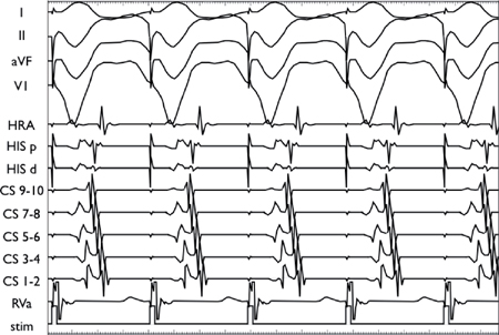
Decremental AV Conduction Using the Extrastimulus Technique
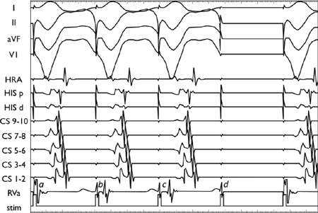
Using a stable drive train (S1), an extrastimulus (S2) is introduced at progressively shorter coupling intervals. AV conduction initially decrements in the AVN, resulting in AH prolongation. As the coupling interval is shortened, there is finally AV block at the level of the AVN (i.e., conduction block without His depolarization).
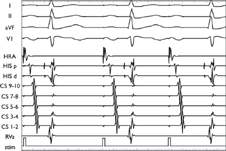
Decremental VA Conduction Using the Extrastimulus Technique
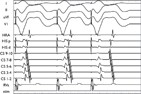
Using a stable drive train (S1), an extrastimulus (S2) is introduced at progressively shorter coupling intervals. The VA conduction demonstrates decremental conduction through the AVN as manifested by progressive VA prolongation with shorter S1S2 coupling intervals.
In contrast to the top two panels, the conduction delay in this panel occurs in the His-Purkinje system rather than the AVN (as demonstrated by the delay in the V2H2 interval).
Conduction Curves
○Technique includes assessment of the anterograde and retrograde conduction curves.
▪ Anterograde conduction curve
• Low atrial A1A2 interval (i.e., on His catheter) vs. output interval (H1H2)
• Low atrial A1A2 interval (i.e., on His catheter) vs. low atrial A2H2 interval
▪ Retrograde conduction curve
• Low atrial V1V2 interval (i.e., on His catheter) vs. output interval (A1A2)
• Low atrial V1V2 interval (i.e., on His catheter) vs. low atrial V2A2 interval
○Interpretation of normal anterograde conduction curve:
▪ As the S1S2 coupling interval is decreased, there is initially a steady relationship with H1H2 and A2H2.
▪ This is followed by:
• Decremental AVN conduction, in which a gradual lengthening in the H1H2 and A2H2 intervals is observed with decreasing A1A2
• Normal HV interval without decremental response, in which there is an increase in A1A2 with decreasing S1S2 at short coupling intervals due to the emergence of intra-atrial conduction delay
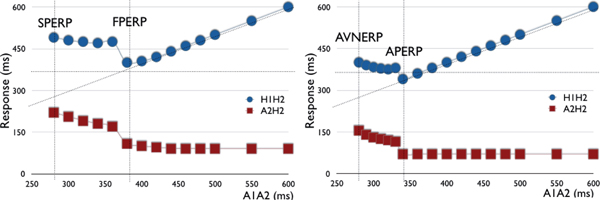
○Interpretation of discontinuous anterograde conduction curves:
| |
The initial portion of the curve represents decremental conduction through the fast pathway. When the refractory period is reached, conduction blocks in the fast pathway (FPERP) and “jumps” to the slow pathway (defined by a ≥50 ms increase in the A2H2 or H1H2 interval with a 10 ms decrease in the S1S2 coupling interval), where it remains decremental until the slow pathway ERP (SPERP). Note: An AH jump without echo beat may be seen in 30% of normal controls. | The initial portion represents non-decremental conduction through the AP. When the refractory period is reached, conduction blocks in the AP (APERP) and “jumps” to the AVN, where it becomes decremental until the AVNERP is reached. Note: There may be decremental AH conduction via the AVN with non-decremental AV conduction via the AP resulting in progressively more negative HV interval/more manifest pre-excitation. |
Difficulties in Determining Refractory Periods
○Refractory periods are dependent on autonomic tone.
▪ Sympathetic tone increases conduction velocity and decreases refractory periods.
▪ Parasympathetic tone decreases conduction velocity and increases refractory periods.
○Accurate estimation of retrograde AVNERP
▪ During ventricular stimulation, the AVN receives its input via the bundle of His.
▪ By definition, the retrograde AVNERP is the longest H1H2 that fails to conduct across the node and back to the atria.
▪ In the situation where the retrograde His is buried in the ventricular EGM, it is better to refer to the retrograde AVNERP as the retrograde ERP of the VA conduction system.
○Conduction of the AVN may continue to atrial tissue refractoriness due to:
▪ The AVNERP being less than the atrial ERP (AERP)
▪ Sufficient delay in the atrial tissue such that the coupling interval of the impulse arriving at the node remains above the AVNERP
○“Gap” phenomenon:
▪ Conduction of an impulse may be blocked at a certain S1S2 interval, then reappear as the S1S2 interval is lowered further before finally disappearing at an even lower S1S2.
▪ This occurs when an impulse is conducted over 2 structures with differing ERPs in sequence.
• At S1S2, there is block in the second structure (e.g., the His-Purkinje system or AVN).
• At shorter S1S2, there is conduction delay (e.g., latency) in the first structure (e.g., the AVN or atrial myocardium) resulting in slowed conduction, thus allowing the impulse to reach the second structure (e.g., the His-Purkinje system or AVN) with an increased coupling interval (i.e., at a point when it has recovered).
• At an even shorter S1S2, there is conduction block in the first structure.
▪ Conventionally, conduction is assumed to cease when the block first disappears.
○Arrhythmia induction:
▪ As the risk of arrhythmias increases as the extrastimulus coupling interval falls, extrastimulus testing around AVNERP may be hampered by induction of supraventricular arrhythmias.
ANTEROGRADE CONDUCTION
Incremental Atrial Pacing
○Performed from the HRA or proximal CS (preferred), or distal CS (for potential left lateral AP)
○Determine the following:
▪ Presence/absence of pre-excitation
▪ The reterograde WCL:
• WCL is defined as CL where 1:1 anterograde conduction ceases (normal 350–450 ms).
• The location of the AV block should be noted (AH or HV).
Extrastimulus Testing
○Should be performed at 2 drive train CLs (typically 600 ms and 400 ms)
○Determine the following:
▪ Anterograde conduction curve (see above)
▪ Refractory periods:
• AVNERP (normal 250–400 ms)
• AERP (normal 180–330 ms)
▫ Note: If AERP is reached before AVNERP, the use of a drive train with a shorter CL may decrease the AERP and increase the AVNERP.
▫ Double extrastimuli (S2S3) may be required if too much intra-atrial conduction delay is observed at short coupling intervals.
Interpretation
○Normal findings are:
▪ As the S1S2 coupling interval is decreased, there is initially a steady relationship with H1H2 and A2H2.
▪ This is followed by decremental conduction in the AVN, leading to a gradual lengthening in the H1H2 and A2H2 intervals.
▪ Discontinuous conduction curves (see above)
▪ Echo beats
• Extrastimulus is conducted down the anterior limb (e.g., slow pathway) and then back up the retrograde limb (e.g., fast pathway).
• Presence of echo beats confirms tachycardia substrate.
• Must be differentiated from intra-atrial reentry.
▫ True nodal echoes have midline caudo-cranial activation (His before HRA).
▫ VA timing of echoes should be consistent over many coupling intervals.
AV Nodal Echo Beat
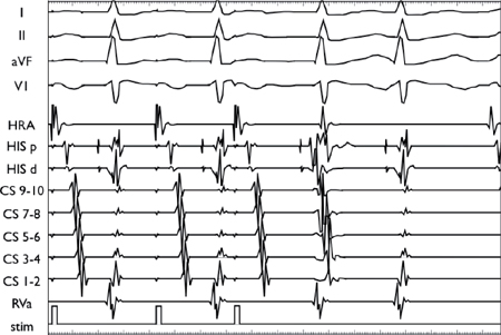
Using a stable drive train (S1), an extrastimulus (S2) is introduced and conducts anterogradely down the slow pathway and then back up the fast pathway. In this example, the impulse conducts back down the slow pathway, resulting in an echo beat before blocking retrogradely in the fast pathway.
RETROGRADE CONDUCTION
○Retrograde conduction is generally not as efficient as anterograde conduction.
▪ Retrograde block occurs at longer CLs.
▪ Normally, block occurs first in the His-Purkinje system.
▪ Block can be hard to see, as His spike is buried in V.
Incremental Ventricular Pacing
○Assess
▪ The presence (or absence) of retrograde atrial activation
▪ The retrograde atrial activation sequence (concentric vs. eccentric)
▪ The retrograde (VA) conduction time
▪ The retrograde VA WCL
• WCL is defined as CL where 1:1 retrograde conduction ceases.
Extrastimulus
○Should be performed at 2 drive train CLs (typically 600 ms and 400 ms)
○Assess
▪ The retrograde conduction curve (see above)
▪ Refractory periods:
• VA conduction block (retro AVNERP)
• Ventricular myocardium ERP (normal 180–290 ms)
Interpretation
○Normal findings are:
▪ Absent VA conduction despite pharmacologic provocation
▪ Concentric atrial activation (midline)
• V2A2 > V1A1 with progressive increase in V2A2 with decreasing V1V2
○Abnormal results include:
▪ Eccentric atrial activation (right and left free wall APs)
▪ Non-decremental VA conduction
▪ VA jump due to:
• Dual AVN physiology with a jump from the retrograde fast pathway to the slow pathway
• Septal AP with a jump from AP to AVN conduction (AVNERP < APERP)
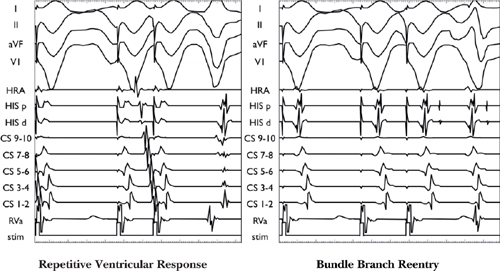
○Ventricular extra beats post-extrastimulus due to:
▪ Bundle branch reentry
• Retrograde right bundle branch block (RBBB) allows S2 to cross the septum and conduct retrograde via the left bundle and then anterograde down the right bundle, which has recovered conduction.
▪ Ventricular echo
• Retrograde conduction up one limb blocks (typically the anterior limb, e.g., the slow pathway), allowing unopposed retrograde conduction up the retrograde limb (e.g., fast pathway) to return anterograde down the anterior limb (e.g., slow pathway).
▪ Repetitive ventricular response
• QRS morphology mimics the paced beats with RVa EGM at the onset of the QRS.
Difficulties in Interpreting Retrograde Curve
○AVN fusion and retrograde latency.
▪ Retrograde atrial activation via the AVN can mask retrograde AP conduction.
▪ Latent retrograde AP conduction can be unmasked by delaying the retrograde nodal activation relative to the AP (i.e., shifting atrial activation from midline to eccentric) via:
• Retrograde extrastimuli
• Pacing at shorter CLs
• Pacing in the LV for left-sided APs (i.e., pacing closer to the AP insertion site)
• IV adenosine to transiently block retrograde AVN conduction
○AVN and septal AP have similar retrograde conduction times.
▪ No VA jump or change in midline activation as conduction switches between the AP and AVN
▪ Pathway may be unmasked by:
• Failure of IV adenosine to induce VA block
• Parahisian pacing
•
Stay updated, free articles. Join our Telegram channel

Full access? Get Clinical Tree


