Cardiac Computed Tomography in Children with Congenital Heart Disease
Rajesh Krishnamurthy
Farahnaz Golriz
Siddharth Jadhav
Introduction
In an ideal world, all children with cardiovascular disease who need diagnostic imaging would receive an accurate, quick, safe, inexpensive, and easily available study. But such a study does not exist. Echocardiography (echo) comes closest to meeting the criteria for an ideal diagnostic test, but there are a number of instances where it is unable to provide all the requisite information for therapeutic decision making due to the lack of acoustic windows, complexity of the anatomy, limited spatial resolution, or the lack of tissue characterization. In these situations, the role of MRI and CT in supplementing the information on echo, and replacing the need for diagnostic catheterization has rapidly grown over the last decade. CT has traditionally played a backup role to cardiovascular MRI in children with congenital heart disease (CHD), having been used in situations where MRI was unsafe, unavailable, limited or contraindicated due to metal, pacemakers, emergent situations, etc. But, the evolution of new generation CT technology over the last 5 years has provided a strong impetus for its use as a primary modality in pediatric cardiovascular imaging by allowing free-breathing nonsedated examinations in all age groups, and significantly reducing the radiation exposure associated with CT, while providing dynamic high-resolution imaging of the heart (1,2). This has resulted in a number of new clinical indications for CT in CHD. This chapter will discuss briefly the technique and limitations of conventional CT, provide an overview of new generation CT technology, compare CT and MRI for pediatric cardiovascular imaging, and explore current indications for CT in pediatric cardiovascular disease.
Overview of CT Technology
Before embarking on a discussion of CT technique, it is essential to provide a historical overview of the evolution of CT as a diagnostic tool for cardiovascular indications. While the advantages of the new generation CT scanners are notable, especially in the setting of pediatric patients, it is important to remember that the most common type of CT technology available worldwide is a 64-detector scanner. Comparing the pros and cons of different generations of CT scanners will provide insight into the critical parameters that are responsible for image quality in CT, and into limitations of each generation of CT technology.
The renaissance of CT can be attributed to two major evolutionary leaps in technology that happened during the last two decades. The first of these occurred in the 1988 with the introduction of helical or spiral CT (3), with simultaneous patient translation and data acquisition. It proved to be a true revolution, allowing faster data acquisition, large volumes of coverage during a single breath hold, multiphasic studies, multiplanar reformation, and three-dimensional (3D) image reconstruction. The next major advance in CT came in 1992, with the advent of the multislice spiral scanner (4), with two parallel arcs of detectors, capable of acquiring two slices of spatial information simultaneously. Multidetector CT (MDCT) has rapidly evolved, and in 2004, 16-detector CT was commonplace, with 40- and 64-detector scanners appearing on the marketplace. In 2014, 64-detector scanners are the norm, with 128-, 256- and 320-detector scanners rapidly becoming the standard of care (5,6). An MDCT with “×” number of detectors can obtain “×” times more data per revolution than single-slice spiral scanners. The modern MDCT scanners also have gantries that spin faster than three revolutions per second, 3× the speed of traditional single-slice scanners, further increasing the speed of data acquisition. The increased speed could be traded, if desired, for improved longitudinal resolution, increased volume of coverage, or improved image quality (decreased image noise). This allows considerable flexibility in CT protocols, especially in small children who cannot lie still, or cannot suspend respiration. New applications, covering almost every part of the body, have evolved based on the major advantages offered by the multidetector scanners: improved volume coverage, temporal resolution and/or longitudinal spatial resolution.
Electron Beam CT
Electron beam CT (EBCT) is a technique that was specifically developed for cardiac imaging in the 1980s. It had been the only CT technique that was able to freeze heart motion, with a temporal resolution of 30 to 100 ms. However, it never gained wide acceptance for CHD evaluation due to its poor spatial resolution (3 mm), and was superseded by MDCT, which provides better spatial and comparable temporal resolution.
Multidetector CT
The first CT scanners had limited use for cardiovascular imaging due to low spatial and temporal resolution, and long scan time. With the advent of 16-detector CT scanner and a rotation speed of 0.4 seconds, cardiovascular imaging entered clinical routine. While the thinnest slice that could be produced with a single-slice CT was 1 mm, 16-detector CT can produce slices as thin as 0.4 mm. Thus, equal resolution can be attained in all three axes, which is called isotropic or isometric imaging (7). The quality of multiplanar reformatting and 3D reconstruction is significantly enhanced with isotropic imaging. The introduction of 64-detector scanner with rotation time of 0.33 seconds pushed CT forward as an important diagnostic tool in evaluating CHD. The increased speed of imaging improved the quality of ECG-gated and multiphasic studies (performed in the arterial phase, venous phase, and delayed phase). Short scan time is also important for utilization of contrast media in the first pass, a critical element of CT angiography.
New Generation CT
The latest advances in CT scanner technology including dual source scanner, wide-detector scanner, higher x-ray tube power, high-efficiency detectors, and improved image processing have further consolidated the role of cardiovascular CT in children, particularly in unsedated patients with higher heart rates. The use of two simultaneous x-ray sources (dual source) coupled with two corresponding detectors, and a short rotation time of 0.25 seconds allow reduction in temporal resolution down to 66 msec, since each of the two arrays travels only 90 degrees to acquire sufficient data for image reconstruction. The second generation of dual-detector scanner has brought a new technique, called high pitch helical (HPH) mode. This technique allows pitch to be increased up to 3.4 without missing data because the data gaps will be filled with the data acquired by the second detector. The primary benefit of HPH mode for pediatric imaging is the high temporal resolution and short scan time (8). Wide-detector scanner utilizing 320 detector is another appealing technology that enables volumetric scanning of a 16 cm craniocaudal length in a single rotation. This will produce temporally uniform images with homogeneous contrast enhancement (5). By shortening the scan time to less then 0.3 seconds, HPH mode technique and volumetric scanning (with wide-detector scanner) enable complete image acquisition within one cardiac cycle even in patients with high heart rates. Equally importantly, by reducing or doing away with the need for overlapping helical imaging, they result in very low radiation exposure, 60% to 80% less than 64-detector scanners (1). Short scan times have documented utility in critically ill patients, and pediatric patients who are unable to breath hold. These techniques have obviated the need for breath holding and sedation for most indications even in neonates and infants (1,2). Short scan times also significantly reduce the amount of contrast media necessary for the investigation, and therefore reduce the risk of contrast-induced nephropathy (CIN). Sequential scanning (the step and shoot mode) is another low-dose prospective ECG-synchronized technique with dual-detector scanners that can reduce radiation dose. Disadvantages of sequential scanning compared to HPH mode technique and wide-array volumetric scanning include stair-step artifacts related to the step-and-shoot mechanism, temporally nonuniform images from scan to scan, and a higher scan time (approximately 2 seconds with second-generation scanner) due to the time required to move the table between each rotation (9,10).
CTA Techniques and Protocols
CT Technique
There are four parts to an optimal CT for pediatric cardiovascular indications: planning, acquisition, processing, and interpretation. Planning is the most important step, ensuring that the appropriate technology and technique are chosen for the given indication, and adjusted to the patient’s unique anatomical and hemodynamic situation. Acquisition involves the actual performance of the study, and involves choice of the scanning and contrast injection protocol, and real time adjustment of the technical parameters depending on the information that is being gleaned from the study. Processing involves sophisticated algorithms that allow the manipulation of the 3D image dataset for advanced visualization such as volume rendering (VR) or virtual angioscopy, or may involve the use of computer programs to obtain quantitative information like vessel caliber, lung perfusion, ejection fraction, calcium scoring, etc., and has become a ubiquitous part of modern imaging, often carried out by dedicated imaging specialists. The final part is interpretation of the images, and creation of the imaging report, which is sent to the referring clinician, and incorporated into the patient record.
Scanning Strategy
Pediatric patients present several inherent problems that are usually not present in adults, including patient motion, inability to breath hold, small body size, increased heart rate and lack of body fat (11). But, the dominating concern in pediatrics is the increased sensitivity of children to radiation. While it is desirable to obtain the highest-quality images in all patients, with retrospective ECG gating, high spatial resolution and high signal-to-noise ratio, this approach invariably results in high radiation exposure. Hence, it is important to think in terms of what needs to be seen, rather than what can be seen. The term used for this low-risk approach is “As Low As Reasonably Achievable” (ALARA) (12,13). Based on the clinical indication, the size of the patient, and the anatomical region of interest, a number of parameters may be adjusted in CT to achieve a high quality study with the lowest radiation exposure possible. A few technical and acquisition parameters will be discussed which are critical to understanding cardiac CT applications, protocols, interpretation, as well as radiation risk. These include tube current, spatial resolution, scan duration, scan range, temporal resolution, ECG gating, contrast agents, image post processing, scan artifacts, and radiation risk.
Tube Current and Gantry Rotation Time
Dedicated infant and pediatric CT protocols typically incorporate low mA techniques, optimized to provide the best image quality, which is a critical part of reducing radiation exposure in children. There is a linear relationship between radiation dose and the tube current. In small children, the mA can be reduced to 80% of the adult value without compromise of image quality, especially for evaluation of fairly large targets such as dimensions of the dilated aortic root, coarctation, and branch pulmonary artery stenosis (1). But, reducing the tube current results in increased image noise. While it is tempting to use low doses for CT angiography, it should be noted that image noise mainly affects low-contrast resolution and evaluation of small structures such as coronary arteries, aortopulmonary collaterals and pulmonary veins, and could lead to a nondiagnostic study for such indications. Therefore, a cautious reduction of the mA must be undertaken, based on the indication for the study and the size of the patient. Numerous other factors, besides tube current, determine the amount of noise—the reconstruction method (360 degrees or 180 degrees), sharpness of kernels and filters, slice thickness, kilovoltage, beam filtering, sensitivity of the x-ray detectors, and quality of the amplifiers. In general, there is a trade-off between mAs, slice thickness, image noise, and spatial resolution. A decrease in diagnostic efficacy due to increased image noise may be offset to some extent by optimizing the contrast injection protocol and reduced respiratory and pulsation motion artifact.
Gantry cycle time (14) is closely related to mA, and a combination of both is mAs (milli-Ampere second). Again, there is a linear relationship between gantry rotation time and radiation dose. In situations where the contrast resolution is very good, as in first-pass angiographic studies, reducing the gantry rotation time to <0.5 seconds is an excellent means of reducing radiation dose as well as scan time.
Beam Collimation and Pitch
The choice of slice collimation and table speed (pitch) is an important determinant of image quality, spatial resolution, and radiation exposure. A narrow x-ray beam collimation has the advantage of better spatial resolution along the z-axis, and reduced partial volume effects. A wider beam collimation has the advantage of less radiation dose and/or less image noise, resulting in better contrast resolution, and shorter scan duration. The choice of collimation setting depends on the clinical indication. Larger volumes are imaged with a large section thickness in order
to reduce the scan duration. If there is a need to depict fine anatomic detail, then collimation should be reduced. MDCT has a thinner collimation than single-slice CT, along with the advantage of shorter scan duration. In multislice volumetric imaging, thin slices (0.5 to 1.5 mm) may also be reconstructed retrospectively from the raw data.
to reduce the scan duration. If there is a need to depict fine anatomic detail, then collimation should be reduced. MDCT has a thinner collimation than single-slice CT, along with the advantage of shorter scan duration. In multislice volumetric imaging, thin slices (0.5 to 1.5 mm) may also be reconstructed retrospectively from the raw data.
Pitch (15,16) is a unitless ratio, originally defined for single-slice spiral CT, as table movement per 360-degree gantry rotation (mm) divided by x-ray beam collimation (mm). Scanning at a pitch less than 1 produces an overlapping scan pattern that increases the radiation dose to the patient, but offers slight advantages for the 3D reconstruction of contours that are roughly parallel to the scanning plane. Increasing the pitch from 1:1 to 2:1 reduces radiation exposure and scan duration by half, but results in a broadening of the slice sensitivity profile of approximately 30%, with the consequence of a higher degree of partial voluming. Higher pitch also has a consequence of reducing z-axis resolution.
In MDCT, there are two definitions of pitch (17), depending on whether a single section collimation (pitch P) or the total collimation of the detector array (volume pitch P*) is chosen as the reference. While the physicists prefer the former, most manufacturers use the latter definition. While P is independent of the number of detector rows, P* increases as the number of detector rows grows. Pitch is a useful marker of image quality. High pitch values degrade image quality due to increased noise, slice broadening and artifacts, but also result in faster coverage and reduced radiation.
The relationship between pitch and slice width is simple and easy to understand in single-slice CT. As pitch increases, so does effective slice width. But, the relationship is complex in multislice CT. By using different slice reconstruction algorithms and an optimal choice of pitch, a thinner effective slice width may be obtained. Thinner slices can also be traded for a thicker slice with less image noise.
While it is tempting to default to a pitch of less than or equal to 1 in order to obtain the best image resolution, there are instances when a shorter scan time is desirable to avoid patient motion, or when the indication does not require a very high spatial resolution. In such cases, pitches of 1.5, 1.7, and 2.0 may be used with resultant savings in scan time and radiation exposure (16). In larger children, changes in image quality between a pitch of 1 and 1.5 are barely discernible (15). Decreased collimation and table increments are reserved for detailed examinations.
Scan Range
This refers to the extent of the body that is covered by the scan. The volume of coverage is directly proportional to radiation dose. This is a powerful tool to reduce radiation exposure in children. Restricting the CT examination to the volume of interest is only possible in cases in which the pathology is either known or likely to be present only in one specific part of the chest. For indications like anomalous coronary artery origin, branch pulmonary artery stenosis, pulmonary vein stenosis, and evaluation of stent patency, the scanning volume can be restricted to the structure of interest. Thus, only one-half to one-third of the chest is exposed to radiation, with corresponding reduction in scan time. Figure 15.1 is a good example of a restricted scan range in a 3-year-old patient with tetralogy of Fallot
and RV-PA conduit placement, bilateral branch pulmonary artery stenosis status post stenting, and severe tracheobronchomalacia, where the field of view was limited to evaluation of the pulmonary arteries and the proximal airway. On the other hand, for indications like heterotaxy (evaluation of the systemic and pulmonary veins, as well as cardiac morphology) (Fig. 15.2), scimitar syndrome, lung anomalies, intracardiac anomalies, aortopulmonary collaterals, or hereditary hemorrhagic telangiectasia, the entire thorax, as well as parts of the neck and abdomen will have to be covered by the scan. Increasing the pitch, and reducing the rotation time can offset the increased scan time and radiation exposure associated with the large volume of coverage.
and RV-PA conduit placement, bilateral branch pulmonary artery stenosis status post stenting, and severe tracheobronchomalacia, where the field of view was limited to evaluation of the pulmonary arteries and the proximal airway. On the other hand, for indications like heterotaxy (evaluation of the systemic and pulmonary veins, as well as cardiac morphology) (Fig. 15.2), scimitar syndrome, lung anomalies, intracardiac anomalies, aortopulmonary collaterals, or hereditary hemorrhagic telangiectasia, the entire thorax, as well as parts of the neck and abdomen will have to be covered by the scan. Increasing the pitch, and reducing the rotation time can offset the increased scan time and radiation exposure associated with the large volume of coverage.
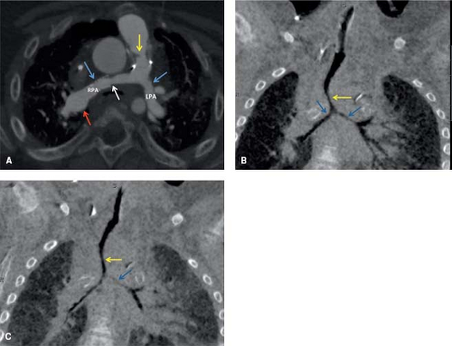 Figure 15.1 Three-year-old female, history of tetralogy of Fallot, status post insertion of right ventricle to pulmonary artery valved conduit, and bilateral branch pulmonary artery stent placement: Axial CTA image (A) shows discrete membranous stenosis of the RV-PA conduit (yellow arrow), proximal to the level of the valve. The right pulmonary artery (RPA) is diffusely narrowed, with more focal narrowing (white arrow) just proximal to the stent in the mid RPA (blue arrow) and dilatation distal to the stent (red arrow). Note also mild diffuse narrowing of left pulmonary artery (LPA). Coronal minimum intensity projection images during inspiration (B) and expiration (C) demonstrate moderately severe long segment narrowing of distal trachea (yellow arrow) and right and left main-stem bronchi (blue arrows) in inspiration (B) and near complete collapse of the distal trachea (yellow arrow) and left main-stem bronchus (white arrow) on expiration, indicative of severe tracheal stenosis and tracheobronchomalacia. |
Temporal Resolution
A high temporal resolution is needed to freeze cardiac motion and avoid artifacts, especially with 64-detector scanners. The 0.3- to 0.4-second gantry rotation time in most modern scanners, combined with half scan reconstruction, and optional multisector reconstruction result in excellent temporal resolution in multislice CT. ECG synchronization of data is necessary to capture the heart in a motionless phase. With single sector reconstruction, only data from the prescribed time range during one cardiac cycle are used for partial scan reconstruction of images. This yields a temporal resolution of about 200 ms for a 0.4-second gantry rotation time. Multisector reconstruction (18) (segmented reconstruction) can increase the temporal resolution by using scanned data from more than one heart cycle for image reconstruction. A temporal resolution of 50 to 65 ms can be reached with up to four sectors. The more sectors that are used, the higher the overlap during data acquisition has to be. This requires lower pitches and results in an increased patient dose. Multisector reconstruction yields the shortest effective scan time, but also needs the highest radiation dose to accomplish this goal.
ECG Synchronization
Non-ECG–gated scanning can provide diagnostic images of the extracardiac vasculature in most patients with CHD. For evaluation of the aorta, pulmonary artery and pulmonary veins, ECG synchronization is usually not necessary. ECG gating is the preferred technique for evaluation of the morphology of the heart chambers, including assessment of ventricle aneurysms, cardiac thrombi, cardiac tumors, evaluation of small aortopulmonary collaterals in pulmonary atresia, and for coronary artery assessment (19). In prospective ECG gating, a prospective trigger is derived from the ECG signal to initiate scanning during a phase of little heart movement. The advantage of prospective ECG gating over nongated scanning is the lower radiation dose, because all data that are acquired are also used for image reconstruction. Prospective ECG gating uses information from the preceding RR interval in order to calculate the trigger delay. The trigger can be selected by the user as a percentage of the RR interval (usually between 40% and 80%) or as a fixed time (absolute delay) after the preceding R peak or before the next R peak. For lower heart rates, 70% to 80% percent of the RR interval yields the best results. But, with higher heart rates (>90 beats per minute); 30% to 40 of the RR interval may yield better results (20). There is one caveat with the use of prospective ECG gating, as in children with high heart rate variability, the starting phase of data acquisition does not precisely match with the preselected starting phase. Temporal padding overcomes this limitation by increasing acquisition time before and after the predicted acquisition window. This technique permits retrospective modification of the reconstruction window to ensure image reconstruction within low motion and identical cardiac phases from one cardiac cycle to another. However, this technique will increase the radiation burden to the patient. In addition, this technique could not be utilized in helical scanning. The acquisition of temporally uniform volumetric data sets with 320-detector scanner enables retrospective half scan reconstruction within different cardiac phases in raw data. This post-acquisition data processing technique, called Target Mode, finds and reconstructs the best motion-free cardiac phase in raw data without increasing the radiation dose to the patient (1). In retrospective ECG gating technique, the tube current is on during the whole cardiac cycle, for approximately five heartbeats using a 64-multislice system, so that data can be reconstructed during the best motion-free phases. This boosts the radiation dose three to four times compared to a nongated examination. The radiation dose can be lessened by using ECG-based tube current modulation that reduces the beam strength during nonoptimal cardiac phases. Retrospective ECG-gated scanning is the technique of choice for evaluation of cardiac function that needs multiphasic images, and for coronary artery assessment in patients with irregular or high hear rates.
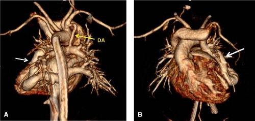 Figure 15.2 Three-day-old female with total anomalous pulmonary venous return (TAPVR): Posterior (A) and anterior (B) volume-rendered images demonstrate TAPVR to the left innominate vein via a meandering vein (white arrow) within the left lung, without evidence of obstruction of the pulmonary veins along their course. Note ductus arteriosus (DA) (yellow arrow) between right innominate artery and right pulmonary artery. |
Patient Preparation
Breath Holding
To eliminate breathing artifacts, the entire anatomy should ideally be scanned within one breath hold. The scans are performed with breath holding and suspended inspiration in cooperative patients. Scans are obtained during quiet respiration in children who are unable to cooperate with breath holding instructions. With the advent of volumetric and HPH mode scanning in new generation CT, the entire volume can be scanned in a fraction of a second, freezing respiration, and doing away with the need for sedation or breath holding.
Premedication
An increased heart rate is unfavorable for optimum cardiac imaging with CT. With the advent of 16-slice scanners, with temporal resolutions of about 50 msec, patients with heart rates of up to 120 bpm can be scanned without premedication. Beta-blockers are a suitable tool to stabilize and reduce the heart rate. When contraindications have been ruled out, beta-blockers are generally recommended for patients with a heart rate above 110 bpm, when 64-detector or lesser generation scanners are used. With new generation CT, the need for beta-blockers to reduce high heart rates is significantly reduced, with prospective and retrospective gating being feasible for heart rates of up to 160 bpm.
Sedation
One of the biggest advantages of modern CT scanners is the short scan duration, and the short set-up time, thus reducing the need for sedation of children (21). In spite of this, sedation is required for evaluation of infants and children who are 5 years of age or younger to prevent gross motion artifacts during scanning. The benefit of scanning without sedation must always be evaluated against the risk of having to repeat the scan due to motion artifact. Neonates can be scanned in their sleep or with immobilization using a soft wrap. Many intensive care patients are relatively immobile, and can be scanned without sedation. Children older than 5 years can generally cooperate after vocal reassurance and explanation of the procedure and will not need sedation. With new generation CT using a volumetric approach with target mode ECG gating and half scan reconstruction (Fig. 15.2), breathing artifact can be avoided even in crying noncooperative patients (1). With these scanners, sedation is restricted to young patients who are combative and unsafe to restrain, or to indications such as coronary assessment.
Intravenous Contrast Agents and Injection Protocol
Contrast Agents
Water-soluble contrast media used in CT are classified as ionic or nonionic. Since osmolality is a measure of the number of dissolved particles (including ions, molecules or aggregates) per liter of water, ionic agents are considered as high osmolar contrast media, and have five to eight times the osmolality of human serum. Examples of ionic media include sodium and/or meglumine diatrizoate and iothalamate. The nonionic contrast media are considered as low osmolar contrast agents, and have one to two times the osmolality of human serum. Examples of nonionic contrast media include iohexol, iopamidol, ioversol, and iodixanol, and are currently the only type of contrast agents used in children, as they are safer and better tolerated than high osmolar contrast media.
Contrast Reaction
Patients receiving intravascular contrast media can have a wide variety of reactions including nausea, vomiting, urticaria, bronchospasm, laryngeal edema, vasovagal reactions, hypotension, seizures, and exacerbation of myocardial ischemia or congestive heart failure. Most of the reactions will occur within 20 minutes of receiving contrast media. Adverse contrast reactions may be classified as idiosyncratic or nonidiosyncratic. Idiosyncratic reactions are dose-independent systemic reactions, which produce signs and symptoms that mimic true anaphylaxis. While their etiology remains unknown, the currently favored mechanism is activation of the complement system. Manifestations include urticaria, bronchospasm, laryngeal edema, and hypotension. Nonidiosyncratic reactions are thought to result from direct chemotaxic or hyperosmolar effects of contrast material. Symptoms include nausea, vomiting, cardiac arrhythmias, renal failure, pulmonary edema, and cardiovascular collapse (22,23). The likelihood of contrast reaction in pediatric population ranges from 0.18% to 0.46% per administration (24,25). Previous reaction to contrast media is the most important risk factor in prediction of reaction. Premedication should be considered in a patient with previous allergic-like reaction to iodinated contrast material; multiple (usually four or more) allergies or a severe allergy to another substance; or asthma with frequent, recent, or severe attacks. Premedication for prevention of idiosyncratic reactions usually consists of prednisone 50 mg administered 13 hours, 7 hours, and 1 hour before, and diphenhydramine administered 1 hour before contrast media infusion, along with the use of low osmolar contrast media (24).
Contrast-Induced Nephropathy
CIN is defined as an increase in serum creatinine levels by >25% or 0.5 mg/dL occurring within 3 days after intravascular contrast administration in the absence of an alternative etiology (26). Usually, the rise in serum creatinine is seen within 1 to 2 days after contrast injection. It peaks in approximately 4 to 7 days, and returns to normal by 10 to 14 days. Risk factors for CIN include pre-existing renal insufficiency, diabetes mellitus associated with renal impairment, large volume of injected contrast media or repeated doses within 72 hours, concurrent use of nephrotoxic drugs like aminoglycosides and nonsteroidal anti-inflammatory agents, dehydration, and severe congestive heart failure. The current evidence suggests that low osmolar contrast media reduce, but do not eliminate the incidence of contrast-induced renal failure. Hence, an alternative diagnostic modality that does not involve the use of systemic contrast media is recommended in high-risk patients. When contrast media injection is essential for a diagnostic workup, a reduced volume of nonionic contrast may be utilized. Pre-scan hydration (volume expansion) also reduces the risk of CIN (26,27,28,29).
Intravenous Contrast Injection
The usual dose of intravenous iodinated contrast media is 2 mL/kg with an iodine concentration of 240 to 370 mg/mL. The greater the iodine concentration, the better the vascular enhancement, but this also increases the contrast viscosity (30,31).
CTA image quality is critically dependent on the level of target vascular enhancement that requires adequate delivery and timing of the intravenously administered bolus of iodinated contrast media. In general, the more rapid the rate of contrast injection, the greater will be the level of vascular enhancement. The degree of enhancement is inversely related to body weight, which is an advantage when imaging small infants.
Contrast injection rate is limited by the size and location of the peripheral intravenous line. The antecubital location is the preferred location in upper extremity due to larger vein size. If this site is not feasible, a forearm/hand vein and foot vein are alternatives.
The lower extremity injection has an added advantage of reducing the incidence of beam hardening artifacts related to high contrast concentration in the innominate veins and superior vena cava (SVC).
The lower extremity injection has an added advantage of reducing the incidence of beam hardening artifacts related to high contrast concentration in the innominate veins and superior vena cava (SVC).
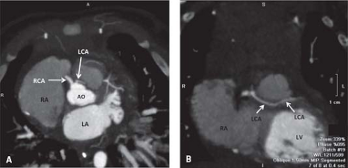 Figure 15.3 CT of AAOCA: 4-month-old male with anomalous aortic origin of the left coronary artery (LCA) from the right sinus of Valsalva with associated intramyocardial course. Axial oblique (A) and coronal oblique (B) maximum intensity projection images show the anomalous LCA origin located in close approximation to right coronary artery (RCA) origin (arrows in A). The LCA shows a long intramyocardial course through the conal septum (arrows in B). |
The optimal injection rate for CTA is 1.5 to 5 mL/s depending on the age of the patient and indication. For example, injection rates of 1.5 mL/s are sufficient for studies in neonates and can be obtained by hand injection through a 24-gauge angiocatheter. Rates of 2 to 3 mL/s, which are optimal for infants and young children, require the use of a power injector and at least a 22-gauge peripheral angiocatheter. Rates of 3 to 5 mL/s require a 20-gauge catheter or a closed system fenestrated catheter (32,33,34). Rates of 5 mL/s are usually used for coronary artery evaluation or to detect pulmonary emboli in adult-sized patients (35).
The use of indwelling central venous and percutaneously inserted central catheter (PICC) lines for contrast injection is generally avoided because the lines limit contrast injection rates to ≤1 mL/s as per manufacturing guidelines (36). Power PICC lines that are designed to be power injected are exceptions to this rule. Umbilical venous catheters (UVC) have been used when peripheral venous access is not possible. A potential problem could arise if the UVC line terminates in an occluded ductus venosus. Diagnostic CTA examinations can be performed, although with limitations, while a patient is treated with extracorporeal membrane oxygenation, by maximizing the administered volume of contrast, and using a delayed phase of contrast enhancement (37).
Contrast Injection Protocols
While high enhancement is required for evaluation of coronary arteries, pulmonary vessels, aortopulmonary collaterals and stent patency, a lower and more constant enhancement level through the heart is required for evaluation of cardiac morphology. Monophasic contrast material injection protocols fulfill the former need, while biphasic injection protocols are more suited to the latter indication (38). Monophasic contrast material injection is not ideally suitable for evaluating cardiac morphology because it leads to a gradual increase in intravascular contrast with time, until a maximum is reached and enhancement rapidly decreases thereafter. This effectively occurs at different points in time for the right and left side of the heart and will therefore make homogeneous enhancement of the heart chambers difficult. It is the most common technique used when the indication is limited to evaluation of a particular segment of the cardiovascular system, like the coronaries, pulmonary arteries, or aortic arch (Fig. 15.3). Biphasic injection protocols are more suitable for evaluating cardiac morphology (Fig. 15.4). To reduce
the high contrast streak artifacts in the right atrium, contrast material concentration may be reduced while maintaining flow rate during the second phase of contrast injection. The first phase of the biphasic injection should last about 10 to 15 seconds, at a flow rate of 2.5 to 4 mL/s. The duration of the second phase is calculated from the injection time, and a flow rate of 1.5 to 2 mL/s is used.
the high contrast streak artifacts in the right atrium, contrast material concentration may be reduced while maintaining flow rate during the second phase of contrast injection. The first phase of the biphasic injection should last about 10 to 15 seconds, at a flow rate of 2.5 to 4 mL/s. The duration of the second phase is calculated from the injection time, and a flow rate of 1.5 to 2 mL/s is used.
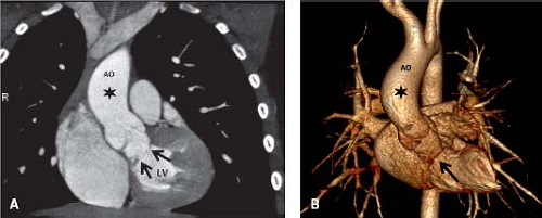 Figure 15.4 Ten-year-old male with membranous subaortic stenosis: Coronal maximum intensity projection (A) and volume-rendered (B) CT angiography images demonstrate membranous subaortic narrowing (black arrows) with poststenotic dilatation of the ascending aorta (asterisk). Note diffuse left ventricle hypertrophy in A. |
Timing of the Contrast Bolus
The objective is to synchronize imaging with the delivery of the bolus of intravenous contrast when the region of interest is at its peak of enhancement. Various methods of timing have been used and include automated bolus tracking, the use of a precontrast test bolus, and empiric methods (31). In older children and adults, almost any method will work well, but in infants, it is much more difficult due to the greater potential differences in cardiac output and the small size of the contrast bolus. For example, in infants, the test bolus may be the size of the study bolus, and bolus tracking may be limited by the posttrigger delay in scan initiation. When injecting a small amount of contrast for infants weighing <10 kg, the delay from the start of injection to start of scanning can be empirically estimated by the circulation time of 12 to 15 seconds. When injecting a large amount of contrast in an adult-sized patient, empirically starting the scan at the end of contrast injection should capture near peak aortic enhancement (31).
A method that utilizes the contrast-covering time concept makes use of the advantages of bolus tracking but compensates for the trigger delay by adjusting the injected flow rate of contrast. This requires a dual power injector (39).
In patients who have undergone a Fontan procedure, the lack of proper contrast mixing in the right atrium due to the sluggish, slow blood flow through the Fontan circuit often results in suboptimal contrast enhancement of the pulmonary arteries and may mimic a thrombosis (Fig. 15.5). By employing simultaneous injections of contrast in both upper and lower extremity veins and by monitoring enhancement of the pulmonary arteries by using bolus tracking, this problem can be minimized (40). One may need to be ready to perform a delayed second-phase CT scan if the dual injection method is unsuccessful.
Stay updated, free articles. Join our Telegram channel

Full access? Get Clinical Tree


