Cardiac Catheterization and Intervention
Radiation protection in the catheterization laboratory
All practitioners delivering ionizing radiation during medical procedures must attend a radiation protection course (IRMER, Ionising Radiation Medical Exposure Regulations 2000). Furthermore, staff working in the catheterization laboratory should be issued with radiation-monitoring badges, for the body and neck, which should always be worn while in the lab. These badges should be checked monthly to assess doses of radiation received by individual members of staff. No unnecessary staff should be within the catheterization lab during a procedure, and all staff that need to be in the lab should be as far from the tube as practical.
Minimizing patient dose
Minimize screening time and minimize acquisition time.
Keep the distance between the X-ray tube and image intensifier to a minimum.
Use collimation and cones to minimize the irradiated area.
Use lower magnifications when possible.
Use the lowest number of frames/second to allow adequate imaging.
For prolonged procedures, the intensifier should be moved regularly, a few degrees, to try to minimize the possibility of skin burns.
Minimizing operator dose
Lead aprons and lead collars should be worn.
Additional screening should be used where available:
lead apron below table.
mobile lead screen to go between the operator and source.
As above, minimize X-ray exposure by reducing screening and acquisition time.
Some projections (e.g. left anterior oblique (LAO)) give much higher scatter of X-ray, and operators should be aware of this.
The dose for an interventional cardiologist has been calculated as 60 mSv (based upon 150 working days per year and 4 interventions per day). The calculated effective dose if the operator wears the correct lead apron and thyroid collar is less than 5 mSv/year. The maximum allowed dose is 20 mSv/year.
Vascular access: the femoral artery
Procedure for femoral artery access
The standard approach for left heart catheterization is the right common femoral artery.
The artery is located by palpating below the inguinal ligament, the ideal position for puncture being approximately 3 cm below the inguinal ligament and slightly lateral to the position of the vessel.
The area should be anaesthetized generously with local anaesthetic (usually 10 mL of 2% or 20 ml of 1% lidocaine). Warn the patient of ‘pins and needles’ or transient numbness in the leg that may be caused by the effects of lidocaine on the femoral nerve.
A small incision (3-5 mm) is made in the overlying skin. The tissue underlying this incision may then be dilated; commonly this is done by using curved ‘mosquito’ forceps.
The procedure used to puncture the artery is known as the ‘Seldinger technique’. A hollow needle is introduced slowly; it is often possible to feel the pulsations of the artery via the needle before the vessel is punctured. When the needle is introduced into the vessel, pulsatile flow confirms its position in the arterial lumen. At this point a 0.035″ wire can be advanced into the vessel and towards the heart; this should be performed under fluoroscopic guidance.
The needle is then withdrawn and a haemostatic sheath (usually 5-8 Fr diameter) is introduced over the wire; the haemostatic sheath allows the introduction of a guide wire and catheter into the femoral artery, while preventing excess bleeding from the femoral puncture site.
Sheath removal (see  Vascular access site management, p. 316)
Vascular access site management, p. 316)
This can be performed immediately after diagnostic angiography, or after an interval of 4-6 hours if heparin has been administered.
Haemostasis can be achieved by manual compression or by using a compression device (e.g. FemstopTM).
Vascular closure devices (e.g. AngiosealTM or PercloseTM) allow earlier removal of sheaths in anticoagulated patients and may reduce bleeding complications.
Complications
Femoral artery dissection
Femoral artery pseudoaneurysm
Distal embolization
Haematoma
Retroperitoneal haemorrhage/haematoma (particularly with high punctures of the femoral artery above the inguinal ligament).
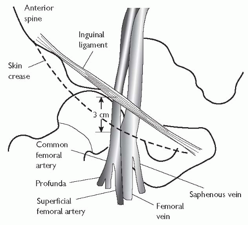 Fig. 6.1 Anatomy of the inguinal canal: the femoral vein lies medial to the femoral artery. The arterial puncture should be made 73 cm below the inguinal ligament. |
Vascular access: the radial artery
The radial approach for coronary angiography is now widely accepted. There are several advantages, including a reduction in vascular complications, and the ability to mobilize patients immediately following their procedure. Patient selection for radial access should include palpation of the radial artery to confirm pulsations are present and then an Allen’s test. In the absence of robust supply via the ulnar artery, the radial approach should not be used.
Procedure for radial artery approach
Consent patient.
Perform Allen’s test.
Remove all jewellery from arm, shave area, and disinfect.
Local anaesthesia: Use 1-2 mL 2% lidocaine instilled via a 25 gauge needle (i.e. enough to anaesthetize, but not to distort the anatomy).
The artery should be palpated with the index and middle fingers, the index finger lifted, and the artery punctured at 45 degrees. The artery should be punctured as proximally as possible, and care should be taken to avoid the flexor retinaculum.
Once pulsatile flow is obtained, a guide wire can then be advanced through the needle and into the vessel.
It is usual to make a small incision in the skin to allow passage of an arterial sheath. Care should be taken not to damage the radial artery while making this incision. Thus the blade should be used to incise in the longitudinal plane, rather than transversely, to reduce the risk of completely transecting the artery.
A variety of long and short sheaths are commercially available. The advantage of long sheaths is that they minimize trauma to the radial artery.
Complications
Radial artery spasm is the commonest complication of radial artery puncture and sheath introduction. There are various techniques to try and prevent radial artery spasm from occurring, these include:
careful patient selection, avoiding small and difficult-to-palpate radial arteries
adequate patient sedation if required—pain provokes spasm
the use of a ‘cocktail’ of drugs introduced directly into the radial artery.
A variety of different regimens have been described. We use 1 mg isosorbide dinitrate, 2.5 mg verapamil, and 2500 U heparin made up to 10 mL with normal saline. Repeated doses of nitrates or verapamil (up to 5 mg) given directly into the sheath or in the catheter may be required
shorter sheaths may be better tolerated
some sheaths have a hydrophilic coating to try to reduce spasm, and for less discomfort on removal
always use a guide wire to straighten catheters prior to removal from the aortic arch through the radial sheath.
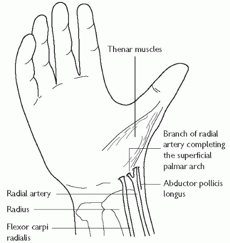 Fig. 6.2 Radial artery anatomy. |
Common radial pitfalls and solutions
Radial loop:
360 degree loop in radial artery. This may be negotiated with a hydrophilic guide wire or angioplasty wire before straightening with a catheter.
Tortuosity in proximal vessels:
this also may be negotiated as above; manoeuvres such as breath holds and gentle ipsilateral arm traction may help.
Recurrent radial artery:
anatomical variant arising from the radial artery below the elbow; may be blind ending. Contrast injection may provide a useful roadmap.
Difficulty accessing the ascending aorta:
breathholding may help to straighten the access route.
Vascular access site management
Femoral sheath removal
Femoral sheaths should only be removed by fully trained members of staff. After diagnostic coronary angiography, when no or little heparin is given, the sheath may be removed immediately. Direct pressure should be applied just proximal to the site of the skin puncture for 5 to 10 minutes. After angioplasty, it is routine to wait for between 4 to 6 hours, an activated clotting time (ACT)<150 s suggests that the effect of systemic heparinization is wearing off, and it is acceptable for the sheath to be removed. Femoral clamps (FemoStop®, RADI Medical Systems) can be used to reduce bleeding complications in patients.
Radial sheath removal
Radial sheaths are removed immediately after both diagnostic angiograms and angioplasty, as the position of the artery renders compression more simple. Compression bands (RadiStop®, RadiMedical Systems USA, TR-BandTM, Terumo). See Fig. 6.3.
Vascular closure devices
Until recently, mechanical compression was the only method for controlling bleeding from vascular access sites in the groin. Larger sheaths and the advent of the more widespread use of glycoprotein (GP) IIb/IIIa inhibitors have increased the risk of bleeding, and made homeostasis more difficult. Recently, various closure devices have been introduced; the aim of these is to increase patient comfort, and reduce puncture-related complications.
Suture-based closure devices
Perclose® (Abbot Vascular, USA): this delivers a suture to the arterial puncture site. The device is sheath-like in nature; needles are positioned above the sheath in the handle, and are deployed by a plunger. A ‘clincher’ that performs a knot-tying function completes a sliding knot.
Collagen-based closure devices
Devices that utilize a bioresorbable collagen plug that is deposited at the site of arteriotomy via a sheath; such devices include the VasoSeal® (Datascope Corp, USA) and Angio-Seal® (St Jude Medical, USA, see Fig. 6.4).
Other mechanical closure devices
StarClose® features a Nitinol® clip that is designed to promote the primary healing process to achieve a secure closure of femoral artery access sites following diagnostic or interventional vascular procedures. This clip provides 360-degree tissue apposition for rapid healing and haemostasis.
Drug-based closure devices
Clo-Sur® PAD (Medtronic, USA): this device contains a naturally occurring biopolymer polyprolate acetate. This polymer has a coagulant property when brought into contact with heparinized blood. The device is placed over the puncture and the haemostatic sheath is removed. Direct continuous pressure is applied until haemostasis is achieved.
 |

Radial closure device: TR BandTM (see Fig. 6.4)
How to place a TR band
Position the spot on the TR BandTM over the radial puncture site, with the sheath in situ.
An assistant should inflate the syringe with the minimal amount of air (usually 12-15 mL) needed to achieve haemostasis, while ensuring the radial artery remains palpable. The operator simultaneously withdraws the sheath from the radial artery.
Add/remove additional air if needed.
Perform regular neurovascular hand observations.
Slowly deflate the TR BandTM over a few hours until bleeding has stopped.
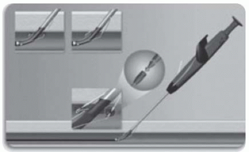 Fig. 6.4 AngiosealTM vascular closure devices. |
Coronary angiography
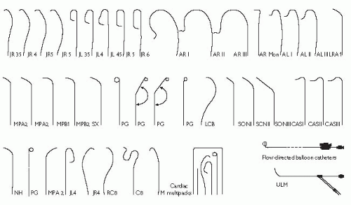
Pre-shaped coronary angiographic catheters
The catheters used in diagnostic coronary angiography come in a wide variety of preformed shapes. In the UK, the most commonly used preshaped catheters are the Judkins Left 4 and Judkins Right 4 (known as the JL4 and JR4 respectively), used to image the left and right coronary arteries, and the pigtail catheter, used for left ventriculography. The diameter of catheters is measured in French gauge (Fr); catheters between 4Fr (0.053″) and 8 Fr (0.105″) are commonly used.
Catheter advancement and manifold usage
A ‘J’-tipped 0.035″ guide wire is placed within the flushed catheter, which is then passed into the haemostatic sheath. The guide wire is advanced ahead of the catheter under fluoroscopic guidance, until it reaches the aortic root, just above the aortic valve. The catheter is then advanced to this position and the guide wire is removed. To ensure that no air or clot is within the catheter, a small volume of blood (5 mL) is aspirated from the catheter directly into a syringe and discarded. The catheter is then carefully connected to a two-way manifold, which allows pressure monitoring, saline flushing, and contrast injection through a closed system.
Contrast injection
Great care must be taken at all times to ensure that air is not injected into the coronary arterial tree. The injection syringe should be filled with contrast from the reservoir, and then the syringe held with the plunger elevated so that any air bubbles rise to the top of the syringe. Contrast should then be injected at a continuous rate, aiming to full opacify the coronary vessel of interest. Care should be taken that the pressure trace is normal before injection—damping suggests an ostial stenosis, excessively deep intubation, or selective intubation of a branch.
Coronary angiography/left ventriculography
Left coronary artery
The 50° left anterior oblique (LAO 50) is the best projection for cannulation of both the left and right coronary ostia.
In reality however, the left coronary ostium is often cannulated with the tower in the anteroposterior (AP) position.
The JL4 catheter will almost invariably cannulate the left coronary ostium without manipulation.
In patients with large aortic roots (large, hypertensive patients), the JL5 (with a larger curve) may be needed, and, conversely, a smaller root may need a smaller catheter curve, the JL3.5.
Right coronary artery
The LAO 50 projection is best used for cannulation of the right coronary ostium.
The JR4 catheter is introduced to the aortic root, until it lies 1-2 cm above the aortic valve.
The catheter is then rotated (‘torqued’) in a clockwise direction, such that the catheter tip rotates towards the right coronary ostium. It may be necessary to reduce the torque to prevent the catheter from over-shooting.
There is often a noticeable lateral movement as the catheter enters the artery.
Before contrast is injected, it must be ensured that the pressure tracing transduced from the tip of the catheter is not damped.
NB: damping can suggest that the catheter has selectively intubated the conus branch of the right coronary artery, and injection of contrast into this vessel can induce ventricular arrhythmias.
Left ventriculography
Position a pigtail catheter a few centimetres above the aortic valve and pull the wire back 5-10 cm to make the catheter tip soft, and push gently (the catheter may cross at this point).
If the catheter does not cross, apply torque as it is gently withdrawn.
If this technique is not successful, use a straight soft-tipped guide wire and catheters that allow that guide wire to be ‘pointed’ at the valve (e.g. AL1 or JR4). This may improve the chances of crossing the valve.
Once the catheter has been placed in a stable (free of ectopics) position in the mid-LV cavity, connect to the manifold and measure the pressure.
Disconnect the manifold catheter connected to a power injector and expel all air.
Set the injection rate: typically 25-30 mL of contrast at a rate of 10 mL/s. Warn the patient about hot flush and the feeling of extra systoles.
When the left ventriculogram has been performed, the catheter is reconnected to the manifold to allow pressure recording as the catheter is withdrawn across the aortic valve (the pullback pressure).
Interpreting the coronary angiogram
Left coronary artery (LCA) angiographic views (Fig. 6.6)
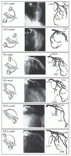 Fig. 6.6 LCA angiographic views. Reproduced with permission from Braunwald E (ed) (2001). Heart Disease: a textbook of cardiovascular medicine. 5th ed. Philadelphia: WB Saunders. |
Right coronary artery (RCA) angiographic views (Fig. 6.7)
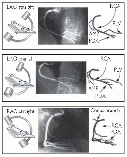 Fig. 6.7 RCA angiographic views. Reproduced with permission from Braunwald E (ed) (2001). Heart Disease: a textbook of cardiovascular medicine. 5th ed. Philadelphia: WB Saunders. |
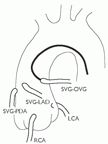
Angiographic study of grafts
It is important to study the surgical record to ascertain how many grafts were placed at the time of the operation. Sometimes, useful information (often from a surgeon’s diagram) can be obtained as to the position in the ascending aorta that the grafts arise from. As a rule, leftwards-facing grafts are best cannulated from the RAO 50 projection, and rightwards-pointing grafts are best cannulated in the LAO 50 projection. It may be necessary to perform an aortogram to visualize the position of grafts. Specialist catheters (e.g. the left coronary bypass catheter or LCB) have been designed to aid cannulation of grafts.
There is usually a predictable anatomy:
patent ductus arteriosus (PDA) grafts originate from the right anterior aspect of the aorta and run vertically to the inferior surface of the heart
obtuse marginal (OM) grafts originate from the left anterior aspect of the aorta and arc towards the posterolateral surface of the heart
left anterior descending (LAD) and diagonal grafts originate from an intermediate position and run laterally towards the anterior interventricular groove.
arterial grafts improve patency rates in coronary artery bypass graft (CABG) and are preferred in contemporary surgery. Left internal mammary artery (LIMA) grafts are usually accessed via the femoral route, but may also be accessed via the left radial approach. Right internal mammary artery (RIMA) grafts are less often used, and can be approached via either the femoral or right radial route.
the left subclavian artery is accessed using a standard JR or multipurpose catheter. Care must be taken when advancing catheters up the subclavian artery. A JR catheter may engage the LIMA directly or may need to be exchanged over a long wire for an internal mammary artery catheter.
small contrast injections may be needed to identify the LIMA ostium.
coronary injections should be acquired in different orthogonal planes to adequately visualize the LIMA and its subtended territory, particularly the point of insertion.
the patient should be warned that they will feel a warm flushing feeling in their arm and neck.
the catheter should be disengaged under fluoroscopic screening and carefully removed over a wire.
Complications of angiography
Peripheral vascular complications
Haematoma
The incidence of haematoma formation is related to the following factors:
length of time the sheath is left in place
gauge (size) of the sheath
anticoagulation
risk factors, e.g. hypertension, obesity, and pre-existing peripheral vascular disease
technique of sheath removal.
Features that suggest a haematoma may require further investigation are an overlying bruit, expansile mass, and a large tense swelling.
Pseudoaneurysm (Fig. 6.9)
A pseudoaneurysm represents a rupture of the femoral arterial wall at the site of puncture, with the formation of a false aneurysm involving the media and adventitia. It is best visualized on ultrasound examination. Small pseudoaneurysms can often be managed by direct compression; however, large pseudoaneurysms may require thrombin injection, or surgical intervention.
Haemorrhage
If prolonged, then direct pressure (either manually or using a clamping device) may be needed. Heparin anticoagulation can be reversed using protamine.
Limb ischaemia
This is rare, and usually occurs in patients with pre-existing limb ischaemia. If limb ischaemia is suspected, then urgent review by the vascular surgical team should be sought.
Contrast reactions
Mild contrast reactions such as rash, urticaria, blurred vision, and rigors are relatively common. These symptoms may settle spontaneously, but are often treated with a combination of IV chlorphenamine 10 mg and IV hydrocortisone 100-200 mg. Anaphylactic reactions are rare; these should be treated with chlorphenamine and hydrocortisone, but also plasma expanders and IM adrenaline.
Vasovagal reactions
These are common both during angiography and at the time of sheath removal, and characterized by hypotension and bradycardia. They are treated with IV atropine and volume expanders.
Arrhythmia
Brief episodes of supraventicular tachycardia (SVT) are common and often transient. During catheter manipulation (especially in the left ventricle (LV)), salvoes of VT are common. Ventricular fibrillation (VF) may occur during coronary artery injection, and should be treated with rapid defibrillation.
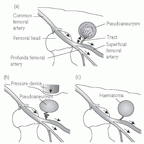 Fig. 6.9 Anatomy of a pseudoaneurysm. (a) Bleeding along a small tract allows blood to collect within the extravascular tissues. Manual compression fails to obliterate the tract (b), and allows the haematoma to persist. Failure of thrombosis of the haematoma produces an extravascular collection with persistent connection and flow from the main artery (c). This can be visualized on ultrasound scan (USS). |
Radial arterial complications
One of the main advantages of the radial route is a reduction in complication rates.
Bleeding
This is more easily managed with direct pressure than from the femoral route.
Compartment syndrome
This is a rare, but potentially catastrophic complication.
Pseudoaneurysm
Rare. Manage as per femoral pseudoaneurysm.
Radial artery occlusion
The rate of radial artery occlusion following radial artery cannulation is unclear—but is probably between 1% and 5%. The rate of occlusion is reduced with smaller sheath sizes, hydrophilic sheaths, and heparin administration.
Right-heart catheterization
Indications for right-heart catheterization include:
evaluation of cardiac shunts
evaluation of valvular heart disease
dyspnoea not explained by non-invasive investigation
investigation for pulmonary hypertension
work-up for cardiac transplantation
investigation for pulmonary hypertension and transplantation should only be performed in specialist centres.
The acute settings in which right heart catheterization can be helpful (e.g. intensive drug therapy in cardiogenic shock) will not be discussed here.
Access to the right heart is usually achieved via the right femoral vein (RFV). The RFV is located 0.5 cm to 1 cm medial to the femoral arterial pulsation (see  Vascular access: the femoral artery, Fig. 6.1, p. 313). An 18-gauge needle, attached to a syringe that is partially filled with saline, can be used to locate the position of the vein, followed by the largerbore needle. When venous blood is freely aspirated, a 0.035″ guide wire is passed into the vein, using a technique similar to femoral artery cannulation, and a haemostatic sheath introduced.
Vascular access: the femoral artery, Fig. 6.1, p. 313). An 18-gauge needle, attached to a syringe that is partially filled with saline, can be used to locate the position of the vein, followed by the largerbore needle. When venous blood is freely aspirated, a 0.035″ guide wire is passed into the vein, using a technique similar to femoral artery cannulation, and a haemostatic sheath introduced.Right-heart catheterization protocol
A ‘multipurpose’ catheter or balloon-tipped catheter may be used.
Ensure that the catheter is flushed, and that the transducer is correctly zeroed.
Advance the catheter to the inferior vena cava (IVC), and further to the right atrium. Record the phasic and mean pressures.
It is customary to then advance the catheter to the pulmonary artery wedge position. Advance into the RV. A combination of rotation of the catheter and gentle traction will allow the catheter to flick upwards into the right ventricular outflow tract (RVOT). It can then be advanced into the main pulmonary artery (PA) and out to the periphery. Occasionally, the guide wire is necessary to achieve this.
Advance the catheter to the pulmonary capillary wedge position, and record phasic and mean pressures.
With a pigtail catheter in the LV, measure and record the LV pressures. Record simultaneous pulmonary capillary wedge pressure (PCWP) and LV pressure, ensuring that the scale allows interpretation of the end-diastolic pressures with accuracy (to assess for mitral valve (MV) gradient).
Withdraw the wedge catheter slightly and record pulmonary artery phasic and mean pressure. Obtain oxygen saturations from the main PA (also right and left pulmonary arteries (RPA and LPA) if a PDA is suspected).
Withdraw the pulmonary catheter to the right ventricle (RV). Measure and record simultaneous RV and LV pressures.
Withdraw the catheter to the RA and measure the pressures again.
The LV catheter should be pulled back to the ascending aorta while the pressure is being monitored to record any pull-back gradient. Aortic saturations should be measured to allow calculation of cardiac output (see Fig. 6.10) and to compare with saturations from the right side if a shunt is suspected.
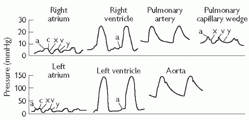 Fig. 6.10 Cardiac catheterization—normal pressure waveforms. |
Cardiac output and left ventricular function
Cardiac output is most often measured using the thermodilution method with a pulmonary flotation catheter.
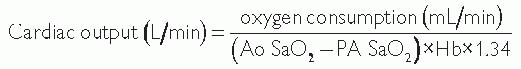
Cardiac output can also be measured using the Fick principle, which assesses the difference between the pulmonary arterial and aortic O2 saturation.
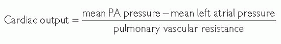
Systemic and pulmonary vascular resistance
Pulmonary vascular resistance (PVR) is an important prognostic factor in patients with valvular heart disease, heart failure, and cor pulmonale. The measurement of PVR and systemic vascular resistance (SVR) is especially important in patients being assessed for cardiac transplantation.
PVR and SVR are measured in Woods units (mmHg/L/min) or dynes/cm5, with 80 dynes/cm5 = 1 Woods unit.

Cardiac catheterization in valve disease
Valve stenosis
Several parameters can be assessed during cardiac catheterization.
Peak-to-peak gradient: aortic and LV pressures are recorded during withdrawal of the pigtail catheter across the aortic valve. The gradient is the difference between peak aortic and peak LV pressure.
Peak instantaneous gradient: more accurate and measured using a double-lumen pigtail catheter.
Mean gradient: the mean pressure gradient measured using planimetry of the area by aortic and LV pressure traces. This can be used to calculate the valve area using the Gorlin equation, and a similar method can be used to assess the mitral valve area.
Valve regurgitation
The severity of aortic regurgitation can be estimated by performing an aortogram. In severe aortic regurgitation, the LV is seen to opacify within one or two beats after contrast injection.
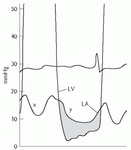
Mitral regurgitation may be assessed by left ventriculography, with contrast seen to opacify the left atrium and pulmonary veins in severe regurgitation. In addition, mitral regurgitation (MR) may be associated with a prominent ‘v’ wave in the pulmonary capillary wedge tracing.
Intravascular ultrasonography (IVUS) is a technology that allows direct visualization of atherosclerotic plaque and the vessel lumen, with recent advances allowing the echogenic characteristics of an IVUS image to give insights into the underlying histology. Ultrasound images are produced by passing an electrical current through a piezoelectric crystal that expands and contracts to produce sound waves when electrically stimulated. These sound waves are reflected from tissues, and return to the transducer, where they are detected and converted to an electrical impulse that can be presented graphically. A phased array of crystals (usually 64) is used, and these are sequentially activated to produce circumferential imaging. The equipment required to perform an IVUS examination involves a miniaturized ultrasound transducer mounted on a catheter (usually 2.6-3.5 Fr gauge), and computer interface that carries out image reconstruction.
Examination technique
Intracoronary isosorbide dinitrate and IV heparin should be administered.
Stay updated, free articles. Join our Telegram channel

Full access? Get Clinical Tree


