Fig. 3.1
Work flow for anatomical and cine imaging. Each scan plane is prescribed starting from two differently angled reference images, using the double oblique technique for the four-chamber view. Starting from the 3 orthogonal scout plane images: axial (a), coronal (b), sagittal (c), cine imaging begins with a vertical long-axis or pseudo-two-chamber view (d). From (d), serial short-axis imaging planes (e) is prescribed parallel to the atrioventricular groove. The four-chamber view, (f) and (g), cuts through the tricuspid and mitral valves and through the ventricular apex. The three-chamber view (h) cuts through the aortic valve to obtain the left ventricular outflow view (i)
As a principle of prescription, an imaging plane is defined as an axial view perpendicular to the body axis and the images are acquired by the serial multiple axial thin slice (1.8 mm thick interpolated to 0.9 mm) to cover the whole heart from the upper abdomen up to the neck vessels. To visualize the 3D-twisted structures like aortic arch or coronary arteries, an imaging plane is also defined unequivocally either by three points, so-called three-point planning, or by how it dissects two separate images previously obtained, the so-called double oblique technique [1].
These images are obtained by ECG gating or vector cardiac gating for compensating heart movement and by navigator gating with prospective slice correction for compensating respiratory motion [3].
3.2.1 Whole-Heart Protocol
To define the intracardiac anatomy without contrast medicine, the vector cardiac real-time navigator-echo technique with prospective slice correction is used to compensate for respiratory motion. A flow-insensitive T2-weighted preparatory pulse for contrast enhancement without the use of contrast material was followed by a localized anterior saturation preparatory pulse, a navigator echo, a spectrally selective fat-saturation pulse (spectral presaturation by inversion recovery), and a 3D-segmented k-space gradient-echo sequence (TR range/TE range, 4.3–5.0/2.2–2.5; flip angle range, 90–100°; radial k-space sampling technique). These sequences were followed by whole-heart imaging with eight phase-encoding steps per cardiac cycle, so-called bright-blood imaging. Slices 1.8 mm thick (interpolated to 0.6 mm) were acquired with a 180–200 mm field of view and were reconstructed with a 512 × 360 matrix (in-plane voxel size, 0.35 × 0.35 mm). The parallel imaging technique of sensitivity encoding was used, usually with accelerator factors 1.3 in the phase direction and 1.0 in the slice direction [3, 4].
The “bright-blood protocol” demonstrates the intracardiac chamber or blood space as a bright white as opposed to the myocardium as a grey using a 3D steady-state free precession (SSFP) MRI sequence (Fig. 3.2). By this imaging protocol, a whole-heart imaging from the multi-slice axial images is obtained as to understand the three-dimensional anatomy of CHD by the sequential and systematic diagnosis of the previously reported segmental approach. The border of the myocardium and blood can be clearly demarcated, which is very beneficial to plan the reconstruction of three-dimensional intracardiac anatomy, just like an ECG-gated contrast-enhanced cardiac computed tomography [2, 6].
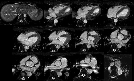
Fig. 3.2
The sequential multi-slice imaging of MRI by whole-heart protocol (bright-blood imaging)
3.2.2 Black-Blood Protocol
There are several imaging sequences of “black-blood protocol.” The 2D black-blood sequence by T1-weighted spin-echo/echo-planar imaging was previously used, but the data was not isotropic and time-consuming. Recently 3D volumetric black-blood angiography and vessel-wall imaging is proposed by using 3D rapid acquisition with relaxation enhancement (RARE) or turbo spin-echo sequence (TSE). This RARE technique has a sequence-endogenous flow-void effect and used with variable or low flip refocusing enables acquisition of 3D T2-weighted imaging [5]. This imaging data is proton density-weighted acquired volume isotropic T2-weighted voxel data which can be extracted from any angle cut-plane images of intracardiac anatomy as a fine black-blood angiography. This protocol is also called as 3D volume isotropic T2-weighted acquisition: VISTA (Fig. 3.3) [5].
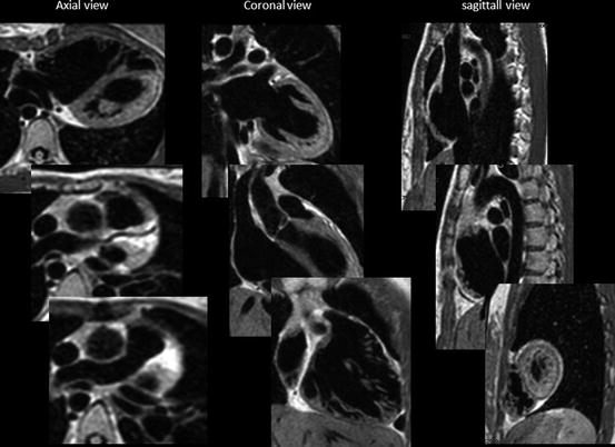
Fig. 3.3
VISTA imaging: from voxel data, three orthogonal sequential multiplane images are expanded
This black-blood protocol is very useful to visualize the intracardiac morphology or vessel wall if there is a significant flow-void lesion like stenosis or regurgitation to cause a signal loss by dephasing in a gradient-echo sequence.
3.2.2.1 Cine MRI
This is the moving image of the beating heart. The sequence of cine MRI is an ECG-triggered turbo field-echo SSFP (one signal acquired per R-R interval; heart rate phase, 80; cardiac synchronization, retrospective gating). The sequence parameters were as follows: 4.2/1.88; flip angle, 60°; field of view, 220 mm. A 192 × 154 matrix with cartesian k-space sampling yielded an in-plane resolution of approximately 1.15 × 0.87 mm (reconstructed 256 × 256 matrix, 0.8 × 0.8 mm). This cine MRI gives blood as a white signal and myocardium as a grey with clear border [1, 3, 4].
A serial multiplane short-axis cine image is used for calculating ventricular volume and myocardial masses, which is widely accepted as a gold standard for ventricular volumetry, since this method does not require the geometric assumptions as opposed to echocardiography or cineangiography.
Because of the TFE sequence, turbulent flow either by stenosis or by regurgitation flow causes loss of signal from dephasing and can be identified as dark streak within the bright-blood pool [1] (Fig. 3.4). This could sometimes interfere the interpretation of the acquired images for intracardiac morphology because of the signal loss due to the lesion of stenosis or regurgitation in the case of cine MRI and whole-heart protocol.
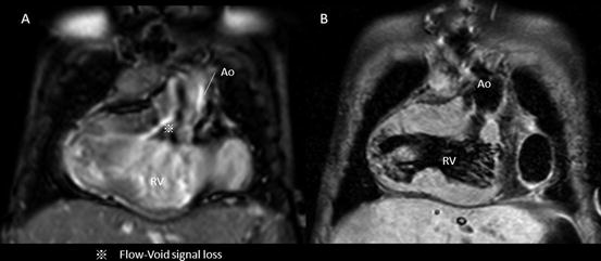
Fig. 3.4
Intracardiac artifact: flow void. Flow void or dephasing the signal by turbulent flow sacrifices the imaging data of intracardiac morphology in cine MRI. This case has the significant subaortic stenosis due to subaortic conus septum and abnormal membranous structures (a); however, the T2-weighted black-blood demonstrated the clear image of subaortic anatomy (b)
3.3 How to Obtain Cardiac Imaging by MRI in Clinical Setting
Since MRI examination takes a longer time to acquire the imaging data, younger children and infants must be sedated to avoid the motion artifact during the examination. In some cases, general anesthesia with or without intratracheal intubation is necessary to secure the respiration and hemodynamic stability to obtain a good MRI imaging [1, 3, 5]. Because of the necessity of sedation or anesthesia, the patients need to be monitored by MRI-applicable heart rate and saturation monitor with video monitoring.
One of our tips to reduce the patient’s respiratory motion is “abdominal-belt technique,” which a towel or blanket belt wraps the patient’s abdomen before applying MRI coil to restrain. This could reduce the diaphragmatic motion to improve the navigation tracking (Fig. 3.5).
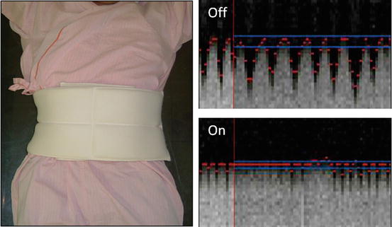
Fig. 3.5
Abdominal-belt technique. Navigation tracing for diaphragmatic motion
Prior to any study, absolute and relative contraindications of MRI study must be addressed [1]. Pacemakers and other electronic implanting devices such as an implanted pump for drug infusion are considered as absolute contraindication. The metallic implantation of non-ferromagnetic devices such as stent, coils, and surgical wires is not the contraindication and is tested for MRI even just after implantation.
3.4 Basic Approach for Making a Diagnosis of CHD
The basics of making a diagnosis for complex CHD are “a segmental approach.” Before starting the intracardiac anatomical assessment, one should understand the whole cardiac structure and anatomy by this classical but effective systematic diagnostic method [7–12].
3.4.1 What Is Segmental Approach/Analysis?
The segmental analysis of CHD was introduced about 35 years ago and is now used worldwide [7–12], not only in pediatric cardiology but also in adult cardiology with CHD [13, 14]. This approach is flexible and applicable to any imaging modality and thus particularly useful in clinical practice. In the segmental approach, the cardiac anatomy is assessed first by dividing the heart into three distinct segments. These segments are the visceroatrial situs, which is evaluated in step 1; the ventricular loop, evaluated in step 2; and the position of the great vessels, evaluated in step 3. These segments are fundamental building blocks of the cardiac anatomy, and the morphological and anatomical features specific to each segment are assessed separately. The understanding of these morphological features of each segment is a key to make a precise diagnosis in the segmental analysis of CHD.
After three-step diagnosis of cardiac segments, two steps evaluated the relationships between the cardiac segments (blocks) at the atrioventricular (step 4) and ventriculoarterial levels (step 5). Finally, associated abnormalities in individual segments are assessed and diagnosed. The notation system developed by Van Praagh (a series of three letters, separated by commas, within parentheses) may be used in conjunction with this approach, as a segmental description [15–17].
3.4.2 Step 1: Determining the Visceroatrial Situs: Atria
There are three types of situs: solitus (S,–,–), inversus (I,–,–), and ambiguus (A,–,–). By definition, the type of situs is determined by the relationship between the atria and the adjacent organs. The first step in the assessment of the cardiac anatomy is to locate and identify the left and right atria. Anatomically, the atrial chamber differentiation is based on the morphological aspect of the atrial appendages. The atrial appendages are earlike extensions of the atria. Typically, the right atrial appendage is broad and blunt (triangular), whereas the left atrial appendage is narrow, pointed, and tubular (fingerlike) (Fig. 3.6). The inferior vena cava (IVC) is often used as a landmark for locating the anatomical right atrium [10–12].
Fig. 3.6
The morphology of the atrial appendage. Right atrial appendage shows broad and blunt triangular or baseball glove-like shape, while the left atrial appendage is narrow and tubular like an index finger shape
The relationship between the right and left bronchi and pulmonary arteries provides a reliable determinant of situs such as eparterial bronchus (bronchus above the pulmonary artery) as a right-side structure and hyparterial bronchus (bronchus below the pulmonary artery) as a left-side structure [10–12].
The position of the heart in the thorax and the orientation of the cardiac apex are also important as determined by the orientation of the cardiac base-apex axis: dextrocardia, mesocardia, and levocardia but not determinative of the situs.
3.4.3 Step 2: Determining the Ventricle Loop: Ventricle
The ventricular loop or ventricular situs may tend rightward (dextro-loop; hereafter, d-loop) (–, D, –) or leftward (levo-loop; hereafter, l-loop) (–, L, –). The cardiac structures are identifiable on the basis of their specific morphological features [10–12]. The shape of the right ventricle (RV) is usually triangular and crescent, while that of the left ventricle (LV) is a bullet shape.
The morphological characteristics of the RV are the presence of an apical moderator band and the subvalvular conus, which is a muscle that demarcated the tricuspid and pulmonary valve (no fibrous continuity of tricuspid-pulmonary junction). The tricuspid valve is usually attached lower at the more apical site of the interventricular septum than the mitral valve (Fig. 3.7) [11–13].
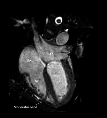
Fig. 3.7
The morphology of the right ventricle
The trabeculae of RV septum is coarse, while that of the LV is smooth. In addition, the papillary muscles of the RV are attached to both the interventricular septum and the free wall, whereas the two papillary muscles of the LV are attached only to the free wall (Fig. 3.8) [18, 19].
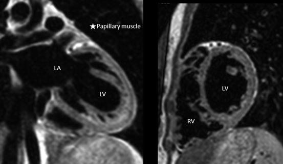
Fig. 3.8
The morphology of the left ventricle
These basic morphological features of RV are preserved even if it is a pulmonic RV (supporting the pulmonary circulation) or systemic RV (supporting the systemic circulation), although the entire shape of each RV is different as shown in Fig. 3.9. The entire shape of pulmonic RV is triangular and crescent, while that of systemic RV is an ellipsoid like a morphological LV [19]. However, in complex cases, it may be difficult to determine which ventricle is the morphological right ventricle and which is the morphological left ventricle. In such cases, the identification may be based on the assumption that in the presence of a right-sided aortic valve, the right ventricle is located to the right of the left ventricle (d-loop), and in the presence of a left-sided aortic valve, the right ventricle is located to the left of the left ventricle (l-loop). This is known as the loop rule [20].
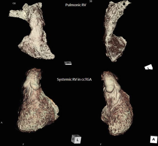
Fig. 3.9
Overall morphology of pulmonic RV and systemic RV
3.4.4 Step 3: Determining the Position of the Great Arteries
Several variants may be observed with regard to the positions of the great vessels. The vessels may be in normal position (solitus) (–, –, N(S)), inverted position (inversus) (–, –, I), D-transposition (–, –, D), or L-malposition (–, –, L). In normal heart, the aorta (Ao) is located posterior to and right of the pulmonary artery (PA) (normal position) and runs crossing each other in spiral relation. If this location shows mirror image of its position and running course, it is called as the inverted position (–, –, I) or inverted normal position (–, –, IN). The position of the great arteries is defined as where the aorta is located in relation to that of pulmonary artery. If the aorta is located anterior to and the right of the pulmonary artery, the position is nominated as “D-transposition.” If the aorta is located anterior to and the left of the PA, the nomination is “L-transposition” or “L-malposition” [7–12, 15–17, 21].
Besides the spatial position of the great arteries, subvalvular conus anatomy is also important. There are four type of conal anatomy: subpulmonary conus (normal), subaortic conus, bilateral conus, and bilaterally absent conus [21].
3.4.5 Step 4: Determining the Atrioventricular Connection
There are five types of atrioventricular connection: concordant (normal), discordant, ambiguous, double inlet, and absent right or left connection. With a normal or concordant connection, the right atrium drains into the morphological right ventricle, and the left atrium drains into the morphological left ventricle. With a discordant connection, the right atrium drains into the morphological left ventricle, and the left atrium drains into the morphological right ventricle. Malposition of the great vessels frequently occurs in association with discordant atrioventricular connection [10–12]. In cases of heterotaxy, the connection is described as ambiguous. Concordant, discordant, and ambiguous may be used to describe the connections when two ventricles are present, whereas double inlet and absent right (or left) connection are used for a univentricular heart. For more precise description, the anatomy and the position of the atrioventricular valve annuli also may be described [10–12, 15–17].
3.4.6 Step 5: Determining the Ventriculoarterial Connection
Besides permanent truncus arteriosus, four types of ventriculoarterial connection may develop: (1) concordant connection (the pulmonary artery arises from the right ventricle, and the aorta arises from the left ventricle); (2) discordant connection, which is synonymous with transposition of the great vessels (the pulmonary artery arises from the left ventricle, and the aorta arises from the right ventricle); (3) double outlet right ventricle (the one and a half of two great vessels arise from the right ventricle); and (4) double outlet left ventricle (the one and a half of great vessels arise from the left ventricle) [10–12, 15–17].
Stay updated, free articles. Join our Telegram channel

Full access? Get Clinical Tree


