4 Angiographic Data
Optimal angiographic data collection is a process of linked steps. Failure of any link breaks the chain and may cause loss of all or part of the data. The chain begins with the nurse’s positioning the patient on the table, followed by catheter placement and correct imaging views, the display of the image for review, and finally the recording and storing of the digital image for the archives. The major causes of poor angiograms include factors specific to the patient (size, hardware), angiographic technique, equipment-related problems, and optical and digital imaging system issues (Table 4-1).
Table 4-1 Causes for Poor Angiograms
| Patient Factors |
| Size |
| Movement |
| Hardware (pacemaker, Harrison rods, multiple surgery with clips, silicone prosthesis) |
| Anatomic conditions (scoliosis, scarred lungs, large heart [fluid]) |
| Angiographer Factors |
| Poor catheter seating (wrong catheter shape, size, anomalous origin, subselective cannulation) |
| Poor contrast opacification (weak injection, volume too small, diluted contrast material) |
| Equipment Factors |
| X-ray generator problems (high heat, quantum mottle, too high kilovoltage, too short pulse width, too long pulse width) |
| X-ray tube problems (anode pitting, wrong focal spot, beam geometry, proximity to image intensifier, poor collimation) |
| Digital imaging program malfunction |
Coronary Angiography
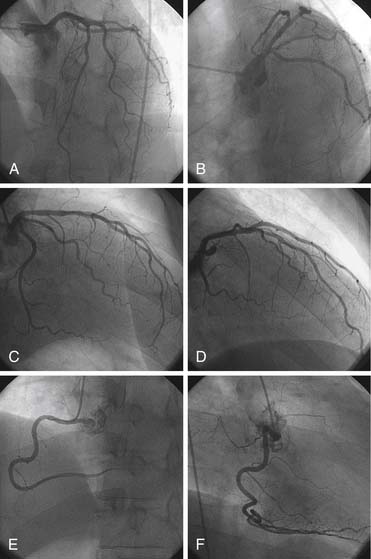
The routine coronary angiographic views should include visualization of the origin and course of the three major vessels and their branches in at least two different planes. Coronary anatomy varies widely, and appropriately modified views must be individualized.
Contrast Media Injection Techniques—Power Versus Hand Injection
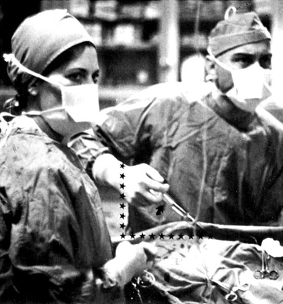
Contrast medium, a viscous, iodinated solution used to opacify the coronary arteries, can be injected by hand through a multivalve manifold. The tip of the syringe is kept pointed down (handle raised up) so that any small bubbles float up and are not injected into the circulatory system (Fig. 4-1). Flow rates are usually 2 to 4 ml/sec with volumes of 2 to 6 ml in the right coronary artery (RCA) and 7 to 10 ml in the left coronary artery (LCA). Hand injection has been used successfully for many years. The use of disposable manifolds, syringes, and tubing is cost effective and safe.
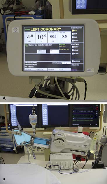
Power injection of the coronary arteries has been used in thousands of cases in many laboratories and is as safe as hand injection. A power injector at a fixed setting might require several injections to find the optimal contrast delivery flow rate. Power injectors now incorporate hand controls, permitting precise operator touch-sensitive variable volume injectors (Acist; Bracco Diagnostics, Med-Rad, etc.), and a computer touch screen for precise contrast delivery settings (Fig. 4-2). The system is highly effective at opacification of arteries through small diameter catheters (<5 F). In addition it is also highly cost affective with the contrast reservoir. Typical settings for power injections are as follows:
Panning Techniques
Most laboratories use x-ray image screen sizes (e.g., 7 inches or less in diameter) that may preclude having the entire coronary artery course visualized without panning over the heart to include the late filling portions of the arterial segments and any collaterals filling. In addition, in most views some degree of panning is necessary to identify regions that are not seen from the initial setup position. Some branches may unexpectedly appear later from collateral filling or other unusual arterial input sources.
Angiographic View Setup Keys
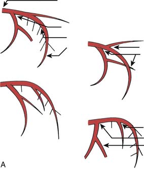
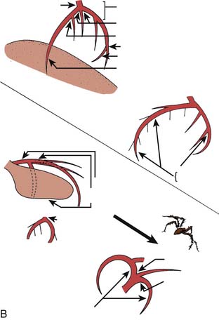
“The best panning is no panning.” Panning motion often overshoots the image targets and information is lost. One key to accurate, optimal coronary cineangiography, obtaining the most information for the least amount of movement, is the initial setup of the catheter on the fluoroscope screen. Figure 4-3 shows the catheter–left main artery setup keys for left anterior oblique (LAO) views in the straight (anteroposterior [AP]), cranial, and caudally angled projections. When the patient is positioned correctly and the setup key followed, only minimal panning is necessary to obtain the information. In the LAO view the operator pans down the left anterior descending (LAD) artery then rightward to identify collaterals going to the right coronary artery (RCA). If the circumflex (CFX) is occluded, then leftward panning will include collaterals going to the distal CFX artery. For the RCA, in the LAO position, the operator pans downward and to the left toward the LAD artery. This will visualize late filling collaterals from the right coronary system to the LAD artery. These motions are diagrammed in Figure 4-3.
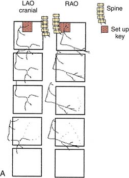
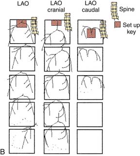
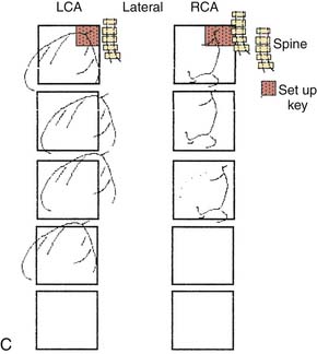
In the right anterior oblique (RAO) projections for the LCA and RCA, the operator pans downward to the apex to identify late filling, left-to-left or right-to-left collaterals. The initial setup keys for catheter tip position on the fluoroscope are summarized in Table 4-2, help the operator include all crucial information for coronary angiography.
Table 4-2 Setup Key Locations for Angiographic Views
| Artery | View | Setup Region on Angulation Grid (below)∗ (No.) | Comment |
|---|---|---|---|
| LAD | LAO cranial | 2 | Set up on screen |
| LAO caudal | 5 | Top, mid line | |
| RAO cranial | 1 | Top, left upper coronary | |
| RAO caudal | 4 | Middle, left side | |
| RCA | LAO cranial/caudal | 1, 2 | Left upper coronary |
| RAO cranial/caudal | 1, 4 | Left upper coronary | |
| LAD/RCA AP | Cranial | 2 |
AP, Anteroposterior; LAD, left anterior descending; LAO, left anterior oblique; RAO, right anterior oblique; RCA, right coronary artery.
| 1 | 2 | 3 |
| 4 | 5 | 6 |
| 7 | 8 | 9 |
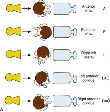
Nomenclature of Angiographic Imaging Views
To obtain optimal information from coronary cineangiography, the operator must use various angulations, unveiling overlapped vessel segments. These views or projections highlight specific and distinct segments of the coronary anatomy and permit discrete visualization of underlying pathologic conditions. Understanding of the usefulness of various radiographic views (and nomenclature) is essential.
For all catheterization laboratories the x-ray source is under the table, and the image intensifier is directly above the patient. The source and image intensifier (also known as a flat panel detector in fully digital laboratories) are moving in opposite directions in an imaginary circle around the patient positioned in the center. The body surface of the patient which faces the observer, determines the specific view. This relationship holds true whether the patient is supine, standing, or rotated (Fig. 4-4).
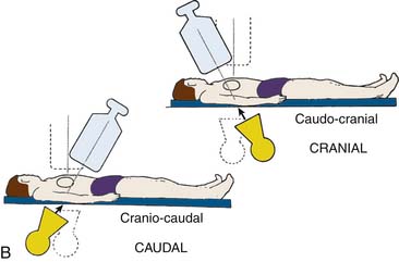
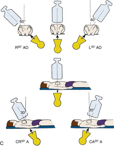
Cranial and caudal views are used to “open” overlapped coronary segments that are foreshortened or obscured in regular views. Note: Cranial views are best for the LAD artery; caudal views are best for the CFX arteries.
The rationale for these routine angiographic views is as follows. Tables 4-3 and 4-4 suggest best setup for visualizing the specific coronary artery.
Table 4-3 Recommended “Key” Angiographic Views for Specific Coronary Artery Segments
| Coronary Segment | Origin and Bifurcation | Course Through Body |
|---|---|---|
| Left main | AP | AP |
| LAO cranial | LAO cranial | |
| LAO caudal∗ | ||
| Proximal LAD | LAO cranial | LAO cranial |
| RAO caudal | RAO caudal | |
| Mid LAD | LAO cranial | |
| RAO cranial | ||
| Lateral | ||
| Distal LAD | AP | |
| RAO cranial | ||
| Lateral | ||
| Diagonal | LAO cranial | RAO cranial, caudal, or straight |
| Proximal circumflex | RAO cranial | |
| RAO caudal | LAO caudal | |
| LAO caudal | ||
| Intermediate | RAO caudal | RAO caudal |
| LAO caudal | Lateral | |
| Obtuse marginal | RAO caudal | RAO caudal |
| LAO caudal | ||
| RAO cranial (distal marginals) | ||
| Proximal RCA | LAO | |
| Lateral | ||
| Mid RCA | LAO | LAO |
| Lateral | Lateral | |
| RAO | RAO | |
| Distal RCA | LAO cranial | LAO cranial |
| Lateral | Lateral | |
| PDA | LAO cranial | RAO |
| Posterolateral | LAO cranial | RAO |
| RAO cranial | RAO cranial |
AP, Anteroposterior; LAD, left anterior descending artery; LAO, left anterior oblique; PDA, posterior descending artery (from RCA); RAO, right anterior oblique; RCA, right coronary artery.
Table 4-4 Routine Coronary Angiographic Views∗
| Left Coronary Artery | For Concentration on Vessel Segment |
| Straight AP or 5 degrees to 10 degrees RAO with caudal | Left main |
| 30 degrees to 45 degrees LAO and 20 degrees to 30 degrees cranial | LAD-circumflex bifurcation |
| 30 degrees to 40 degrees RAO and 20 degrees to 30 degrees caudal | Circumflex + marginal branches |
| 5 degrees to 30 degrees RAO and 20 degrees to 45 degrees cranial | LAD + diagonals |
| 50 degrees to 60 degrees LAO and 10 degrees to 20 degrees caudal (spider view) | LAD-circumflex bifurcation, circumflex, marginals |
| Lateral (optional) | Bypass conduits to LAD |
| Right Coronary Artery | For Concentration on Vessel Segment |
| 30 degrees to 45 degrees LAO and 15 degrees to 20 degrees cranial | Proximal, mid, PDA |
| 30 degrees to 45 degrees RAO | Proximal, mid, PDA |
| Lateral (optional) |
AP, Anteroposterior; LAD, left anterior descending artery; LAO, left anterior oblique; PDA, posterior descending artery (from right coronary artery); RAO, right anterior oblique.
∗ Note: The lateral view is a useful addition to these views for both coronary arteries. In addition, the four most common views for the left coronary artery when performed LAO cranial, RAO cranial, RAO caudal, and LAO caudal form a box around the patient. Look first at the LAD (cranial views) and then at the circumflex (caudal views). This box should be on every study with rare exceptions.
Left Coronary Artery
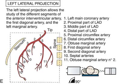
(From Bertrand ME, editor: Coronary angiography, Lille, France, 1979, French Society of Cardiology.)
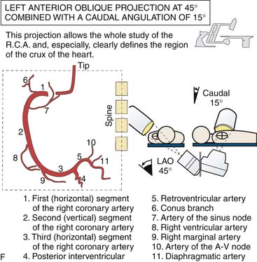
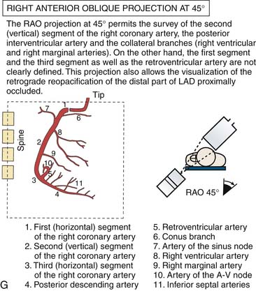
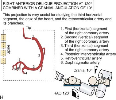
Right Coronary Artery
Technical note: Because of individual variations in anatomy, small (1- to 2-ml) test injections during patient inspiration helps the operator obtain the appropriate oblique and axial (cranial-caudal) angulations and set up for panning.
Saphenous Vein Graft Angiographic Views
General strategy: Following LCA and RCA angiography and visualization of missing or reciprocally filled vessel segments, the operator should the proceed to saphenous vein graft (SVG) angiography using key views for specific coronary artery segments (see Tables 4-3 and 4-4) and subsequent need to determine contingency views or addition of special views.
Usefulness of Biplane Coronary Angiography
Simultaneous biplane cineangiography, although uncommonly used, provides accurate images from two different simultaneous points of view and is advantageous in performing complete coronary or ventriculography with reduced contrast volumes and radiation exposure. Biplane angiography helps to unravel complex coronary or structural cardiac anatomy (Table 4-5). Biplane angiography is most useful in the pediatric population and those patients with renal failure. Biplane is advocated in some adult interventional procedures like complex electrophysiologic mapping or novel structural heart disease implant device placements (e.g., ventricular septal defect (VSD) occluders).
Table 4-5 Biplane Coronary Angiography
| Advantages |
| Disadvantages (depending on experience) |
| Major limitations or objections by operators: |
| Method to overcome these objections: |
The value of biplane information must be balanced against cost and difficulty of use. The traditional set up for biplane coronary angiography required the patient’s heart to be in the exact center of the two planes (the isocenter) and then the AP and lateral planes were angled in orthogonal projections (e.g., LAO-cranial and RAO-caudal, Fig. 4-9) This setup often resulted in more difficulties than it solved. Depending on the team, operator frustration increased with the perceived additional set up and procedure time needed to center the patient and repeat images that were lost when panning in one plane and out of the other. The potential savings of contrast media and radiation exposure were also lost when the two orthogonal planes were not perfectly positioned.
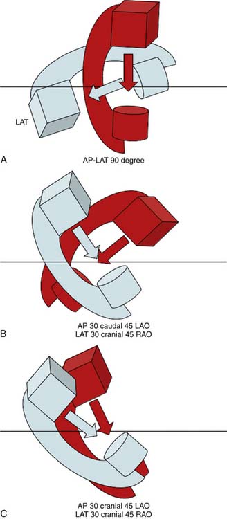
A novel setup makes biplane angiography simple, quick, and effective. The method uses concordant cranial or caudal imaging views such as cranially angled LAO/RAO projections and then moving both C-arms to caudally angled LAO/RAO projections (see Fig. 4-9). In this way, angiographic information is not lost when panning because the heart moves in a similar direction albeit from the opposite side (but not cranial versus caudal). With the concordant biplane setup, contrast use was halved, the radiation dose reduced, and the procedure time shortened.
Biplane angiography may provide additional information documenting the true path of anomalous coronary arteries beyond single plane imaging. For example, Wang et al (Cathet Cardiovasc Intervent 42; 73-78, 1997) used the biplane images and confidently demonstrated the several potential courses of the anomalous Left main artery (the retroaortic course, intraarterial, and anterior looping or intraseptal courses). The levophase of the ascending aorta also provides a good view of the posterior aortic wall further assisting in determining the course of the coronary artery. Biplane was helpful to obtain the “dot and eye” assessment of the anomalous left main (LM) from the right sinus of Valsalva with fewer views required (see Serota et al).
Assessment of Coronary Stenoses
Assessment of the Degree of Narrowing
The degree of an angiographic narrowing (stenosis) is reported as the estimated percentage lumen reduction of the most severely narrowed segment compared with the adjacent angiographically normal vessel segment, seen in the worst x-ray projection. Because the operator uses visual estimations, an exact evaluation is impossible. There is a ± 20% variation between readings of two or more experienced angiographers. Stenosis severity alone should not always be assumed to be associated with abnormal physiology (flow) and ischemia. Moreover, coronary artery disease is a diffuse process and thus minimal luminal irregularities on angiography may represent significant albeit nonobstructive CAD at the time of angiography. The stenotic segment lumen is compared with a nearby lumen that does not appear to be obstructed but that may have diffuse atherosclerotic disease (Fig. 4-10). This explains why postmortem examinations and intravascular ultrasound imaging (IVUS) describe much more plaque than is seen on angiography. The percent diameter is estimated from the angiographically normally adjacent segment. Because coronary arteries normal taper as they travel to the apex, proximal segments are always larger than distal segments, often explaining the large disparity among several observers’ estimates of stenosis severity. Area stenosis is greater than diameter stenosis and assumes the lumen is circular, whereas the lumen is usually eccentric. In general, four categories of lesion severity can be assigned:
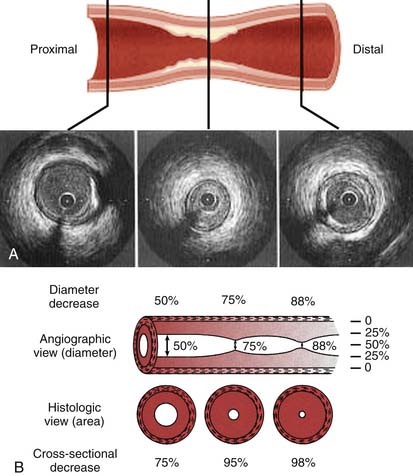
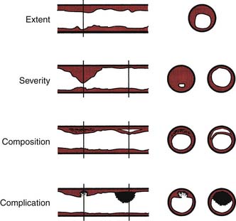
Technical note: Stenosis anatomy should not be confused with abnormal physiology (flow) and ischemia, especially for lesions 40% to 70% narrowed. For nonquantitative reports, the length of a stenosis is simply mentioned (e.g., LAD proximal segment stenosis diameter 25%, long or short). Other features of the coronary lesion may not be appreciated by angiography and require IVUS (Fig. 4-11).
Classification of Angiographic Blood Flow (TIMI Grades)
The four grades of flow are described as follows:
In acute myocardial infarction trials, TIMI grade 3 flows have been associated with improved clinical outcomes. The quantitative method of TIMI flow uses cineangiography with 6 F catheters and filming at 30 frames per second. The number of cine frames from the introduction of dye in the coronary artery to a predetermined distal landmark is counted. The TIMI frame count for each major vessel is thus standardized according to specific distal landmarks. The first frame used for TIMI frame counting is that in which the dye fully opacifies the artery origin and in which the dye extends across the width of the artery touching both borders with antegrade motion of the dye. The last frame counted is when dye enters the first distal landmark branch. Full opacification of the distal branch segment is not required. Distal landmarks used commonly in analysis are (1) for the LAD, the distal bifurcation of the LAD artery; (2) for the CFX system, the distal bifurcation of the branch segments with the longest total distance; and (3) for the right coronary artery, the first branch of the posterolateral artery. The TIMI frame count can further be quantitated for the length of the LAD coronary artery for comparison the two other major arteries; this is called the corrected TIMI frame count (CTFC). The average LAD coronary artery is 14.7 cm long, the right 9.8 cm, and the CFX 9.3 cm, according to Gibson and colleagues. CTFC accounts for the distance the dye has to travel in the LAD relative to the other arteries. CTFC divides the absolute frame count in the LAD by 1.7 to standardize the distance of dye travel in all three arteries. Normal TIMI frame count (TFC) for LAD is 36 ± 3 and CTFC 21 ± 2; for the CFX, TFC = 22 ± 4; for the RCA, TFC = 20 ± 3. Neither TIMI flow grades nor CTFC correspond to measured Doppler flow velocity. High TFC may be associated with microvascular dysfunction despite an open artery. CTFC of <20 frames was associated with low risk for adverse events in patients following myocardial infarction. A contrast injection rate increase of ≥1 mL/sec by hand injection can decrease the TIMI frame count by two frames. The TIMI frame count method provides valuable information relative to clinical responses after coronary interventions.
Collateral Circulation
| Grade | Collateral Appearance |
|---|---|
| 0 | No collateral circulation |
| 1 | Very weak (ghostlike) reopacification |
| 2 | Reopacified segment, less dense than the feeding vessel and filling slowly |
| 3 | Reopacified segment as dense as the feeding vessel and filling rapidly |
Problems and Solutions in the Interpretation of Coronary Angiograms
Poor Opacification
Poor contrast opacification of the vessel may lead to a false impression of an angiographically significant lesion or lucency that could be considered a clot. Inadequate mixing of contrast material and blood could be seen as a luminal irregularity. A satisfactory bolus injection of contrast material must be delivered if adequate opacification is to be achieved and the angiogram interpreted correctly. Contrast delivery can be enhanced by use of a larger catheter, injection during Valsalva maneuver phase III, or use of a power injector.
Special Problems
Left Main Coronary Artery Stenosis
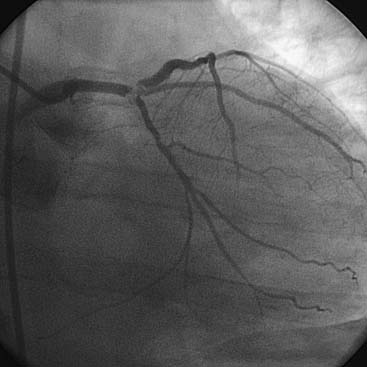
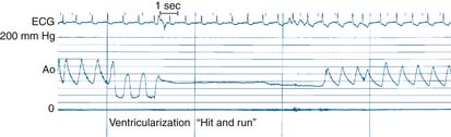
A commonly encountered and potentially critical problem is safe coronary angiography of patients who have LMCA stenosis (Fig. 4-12). The approach to the patient with LMCA stenosis is one of the few situations in which the operator and team may directly affect the life and death of the patient. The LM stenosis may occur at the ostium, mid-body, or distal bifurcation of LAD/CFX and has implications for coronary artery bypass graft (CABG) and PCI decisions.
LMCA stenosis is commonly associated with two clinical presentations:
Technical notes for the angiography of the LMCA stenosis:
Left Ventriculography in Patients with Left Main Coronary Artery Stenosis
Important points for postcatheterization care of the patient with LMCA stenosis:
Angiography of Common Coronary Anomalies
Anomalous Origin of the Left Main Coronary Artery from the Right Sinus of Valsalva
Stay updated, free articles. Join our Telegram channel

Full access? Get Clinical Tree


