Patient characteristic
Better candidate
Worse candidate
Symptoms
Highly symptomatic
Asymptomatic
Failed Class I or III antiarrhythmic drugs
>1
0
AF classification
Paroxysmal
Long standing persistent
Age at time of ablation
Younger (<70)
Older (>70)
Left atrial size
<80 cc
>120 cc
Ejection fraction
Normal
Reduced
CHF
No
Yes
Concomitant cardiac disease
No
Yes
Pulmonary disease
No
Yes
Obstructive sleep apnea
No
Yes
Obesity
No
Yes
Prior stroke
No
Yes
In our own experience we have found that left atrial volume is the predominant predictor of AF ablation success. In a subset of 88 patients with both paroxysmal and persistent AF at our institution undergoing AF ablation, left atrial volume measured by CT strongly predicted AF recurrence following ablation. The recurrence rate increased from 10 % in patients with left atrial volumes of less than 70 cc and increased to over 33 % in patients with left atrial volumes between 110 and 129 cc. In patients with a left atrial volume of 130 cc or larger the recurrence rate after ablation was more than 90 % and appeared to function as a threshold for failure [19] (Fig. 6.1).
Figure 6.1
Failure rate after AF ablation depending on left atrial volume by CT
As shown in the ROC analysis, the frequency of AF recurrence after ablation increases as left atrial volume increases. The recurrence rate increase from 10 % in patients with small atria with volumes <70 cc and increases to over 33 % in patients with left atrial volumes between 110 and 129 cc. A left atrial volume of at least 130 cc as measured by CT appears to function as a threshold. Failure rate in patients with a volume of 130 cc or larger had an AF recurrence rate of more than 90 %.
Complications of AF Ablation and Anatomic Considerations
Catheter ablation of AF is one of the most complex ablation procedures performed by electrophysiologists. It is therefore expected that AF ablation is associated with more extensive and higher complications rates even in experienced centers. The most recent worldwide survey of AF ablation included 45,115 procedures in 32,569 patients. Thirty two deaths occurred resulting in a mortality rate of 0.98 per 1,000 patients. The most common causes of death included tamponade, stroke, atrioesophageal fistula and massive pneumonia [20]. It should be noted that this data was derived from voluntary surveys and quite possibly significantly underestimates the true morbidity and mortality associated with AF ablation.
Complications associated with AF ablation may be related in part to regional differences in left atrial (LA) transmural wall thickness. In an effort to investigate this, we measured LA wall transmural thickness in 34 human heart specimens using calipers in five anatomic areas frequently targeted during AF ablation (anterior wall, septum, mitral isthmus, posterior wall and roof). The roof was the thinnest region measuring significantly less than each other area. The septum was the thickest area [21]. Significant regional differences exist among the different anatomic areas within the left atrium and lower power and temperature should be used in anatomic regions within the left atrium known to have thinner transmural wall thickness.
Approach to the Left Atrium
Transseptal Puncture
Transseptal puncture (TSP) is the conventional approach to accessing the left atrium. TSP can be challenging even for experienced physicians. In our laboratory we rely on several fluoroscopic and intracardiac images when performing TSP. The intracardiac echo (ICE) catheter is placed in the superior vena cava (SVC) viewed from the anterior posterior (AP) fluoroscopic view. The ICE catheter is then pulled down inferiorly in the AP view until the fossa ovalis is clearly visualized. At this point it is important to view the anatomic relationship of the ICE catheter and the os of the coronary sinus identified by the coronary sinus catheter. Positioning the ICE catheter too inferiorly and thus closer to the coronary sinus os may result in a TSP location that is too low which can allow the trans-septal needle to fall into the right ventricle when applying forward pressure at the time of the puncture. Once a clear image of the fossa ovalis is seen, the transseptal needle is advanced into the introducer of the guide sheath and pulled down from the SVC in the AP view until clear tenting is seen on the ICE image (Fig. 6.2). We prefer to perform the actual puncture in the left anterior oblique (LAO) fluoroscopic view and the camera is moved from an AP view to 40° LAO at this time. At this point forward pressure is applied to the sheath and introducer until further tenting is seen. The trans-septal needle is then advanced until the fossa ovalis is crossed. It is our preference to use a radiofrequency powered transseptal needle as we have found that this results in high success rates and lower fluoroscopy times. Confirmation of the trans-septal needle location is then assessed by injecting contrast dye with the aid of a manifold into the needle hub. The transseptal needle is then removed from the body leaving the sheath introducer just across the fossa with the tip in the left atrium. A 0.32 guide wire is then advanced through the introducer into the left superior pulmonary vein (Fig. 6.3). It is only after this step that the sheath is advanced into the left atrium by pushing the sheath and introducer at the same time over the guide wire. At times it can take moderate applied pressure to advance the sheath into the left atrium. Advancing the sheath across a guide wire placed in the left superior pulmonary vein prevents the sheath and introducer from forcibly hitting the free wall of the left atrium as it is advanced.
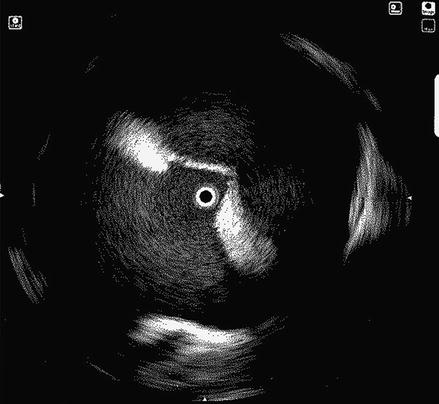
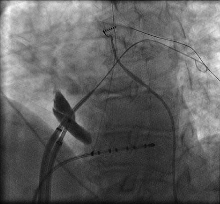
Figure 6.2
ICE image showing clear tenting of the fossa ovalis prior to transseptal puncture
Figure 6.3
A guide wire is advanced into the left superior pulmonary vein after the introducer enters the left atrium. This serves as a guide when advancing the sheath to prevent the sheath/introducer combination from forcibly hitting the left atrial free wall
Catheter Manipulation Within the Left Atrium and Pulmonary Veins
Once access to the left atrium has been achieved, we routinely inject contrast into the left and right pulmonary veins (Figs. 6.4 and 6.5). Despite the fact that we utilize three dimensional electroanatomical mapping it is still very useful to have a fluoroscopic image of the pulmonary vein ostia and the relationship of the ostia to the cardiac border and spine which varies significantly between individual patients. This serves to increase the safety of the procedure with fluoroscopic confirmation that the ablation catheter is well outside the pulmonary vein ostia.
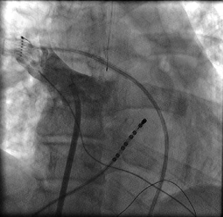
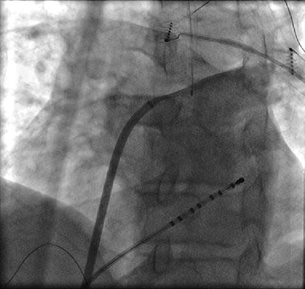
Figure 6.4
Contrast injection into the right superior pulmonary vein
Figure 6.5
Contrast injection into the left superior pulmonary vein. Also seen is the esophageal temperature probe posterior to the vein
Catheter manipulation within the left atrium can be broken down into the pulmonary veins and six major anatomic regions: right anterior wall, right inferior wall, left anterior/ridge, left posterior wall, left atrial roof and appendage. If one were to draw an imaginary line down the middle of the left atrium, it is our preference to use AP or shallow RAO fluoroscopic views when manipulating the ablation catheter to the right of that line and LAO for any catheter movement to the left of that line.
The pulmonary vein ostium are posterior structures with in the left atrium. As such posterior torque on the catheter and sheath is necessary to access the veins. The left superior pulmonary vein (LSPV) can be entered by directly advancing the ablation catheter from the trans-septal site with clocking the catheter and sheath in a posterior direction. It can be virtually impossible to define the left atrial appendage from the LSPV on two dimensional fluoroscopy. It is therefore imperative that one carefully looks at the local atrial electrogram as the catheter is being advanced into the LSPV. If the catheter is advanced in too much of an anterior direction, the left atrial appendage can be entered inadvertently and this would be associated with a large amplitude atrial electrogram which should immediately be recognized by the operator. This is in contrast to what one would expect when advancing the catheter in to the LSPV which reveals a diminishing electrogram amplitude. The left inferior pulmonary vein can be entered by maintaining the same posterior torque and advancing the catheter slightly in the inferior direction. The real time impedance should also be carefully monitored. A high impedance (over 110 Ω) would suggest that the catheter is too distal within the pulmonary vein and ablation should then be avoided.
The right superior pulmonary vein (RSPV) is easily accessed by pulling the catheter out of the LSPV and clocking the sheath and catheter across the high posterior wall until the catheter falls into the RSPV. After mapping the RSPV the catheter can be rotated in a further clockwise direction until it falls out of the vein onto the high anterior wall of the left atrium. At this point the sheath and the catheter can be pulled down together in an inferior direction to the level of the trans-septal puncture to obtain the remainder of the anteroseptal wall (Fig. 6.6).
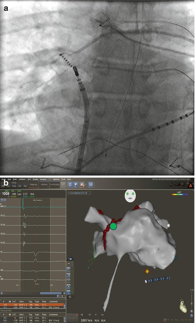
Figure 6.6
Approach to anterior wall outside the RSPV. Corresponding fluoroscopic image (a) and location (green circle) on three dimensional electroanatomical map (b). The ablation catheter is rotated in a clockwise direction from inside the RSPV until it falls on the anterior antrum/wall. The ablation catheter and sheath and then pulled sequentially in an inferior direction to map or ablate the remainder of the anterior wall to the level of the trans-septal puncture
The right inferior pulmonary vein (RIPV) and surrounding left atrium can be one of the most difficult anatomic regions of the left atrium to reach. This is especially true with smaller left atriums where there is very little distance between the trans-septal puncture site and the inferior os of the RIPV. The os of the RIPV is located much more posteriorly than any of the other veins which adds to the challenge of entering this vein and performing ablation around its’ entire circumference. When accessing the RIPV, it is our preference to point the sheath toward the LSPV. The catheter is then deflected more than 180° with posterior (counter clockwise torque) until the RIPV is entered (Fig. 6.7). The catheter will not leave the fluoroscopic cardiac silhouette as it does with the other three veins because of the very posterior direction of the RIPV. The right posterior wall and low right anterior wall below the trans-septal puncture site can then be mapped from this configuration by counter clockwise or clockwise catheter rotation respectively.
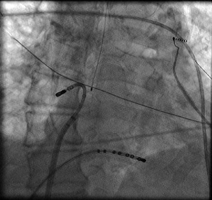
Figure 6.7
Approach to the right posterior wall and right inferior pulmonary vein – Catheter position shown on corresponding AP fluoroscopy and three dimensional electro-anatomical map views. The sheath is directed toward the left and pulled back into the right atrium. The ablation catheter is then positioned in the opposite direction of the sheath and moved in an inferiorly and superiorly to manipulate the entire right posterior wall. Advancing the catheter in this position will access the right inferior pulmonary vein. Also seen is the esophageal temperature probe placed at the level of the distal tip of the ablation catheter
There are two equally effective methods to both map and ablate along the left atrial roof. The roof of the left atrium is not a flat structure. The roof immediately outside of the LSPV is much more superior than the roof anatomy as it enters the RSPV. This superior to inferior direction of the roof must be taken into account as the catheter is manipulated across the left atrial roof. In an AP fluoroscopic view, the tip of the ablation catheter can be placed in the os of the RSPV with the sheath pointed toward the left. The curvature of the catheter is then relaxed allowing the catheter to fall across the roof from right to left (Fig. 6.8). Alternatively, the catheter can be placed into the os of the LSPV. The catheter and sheath are then clocked together in a sequential fashion across the posterior aspect of the roof until the os of the RSPV is reached. With this method local esophageal temperature must be carefully monitored given the more posterior roof line that is created.
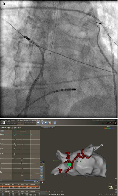
Figure 6.8
Corresponding catheter position in AP fluoroscopic (a) and three dimensional electro-anatomical map (b) (green circle) views. To obtain the left atrial roof anatomy the sheath is pointed to the left and the ablation catheter is positioned in the opposite direction with the tip just outside the right superior pulmonary vein. From this position, the catheter curve is slowly released, thus allowing the catheter to sweep the roof and ends at the ostium of the left superior pulmonary vein
The ridge of the left atrium is located between the anterior os of the LSPV and the left atrial appendage. There is significant anatomic variation to this structure between patients. Higher power settings are often required to achieve bidirectional electrical block along the ridge. The ridge can be ablated from the pulmonary venous or appendage side. It is our preference to ablate along the venous side of the ridge. The ablation catheter is advanced into the LSPV and the sheath is advanced well into the left atrium over the catheter. The catheter is then withdrawn as counterclockwise torque is applied to the sheath. Ablation is performed when both an acceptable electrogram and impedance is obtained. This is one area of the left atrium where more sheath support is required. Without the sheath support, small anterior or posterior movements of the catheter will cause it to fall into the left atrial appendage or LSPV respectively (Fig. 6.9).
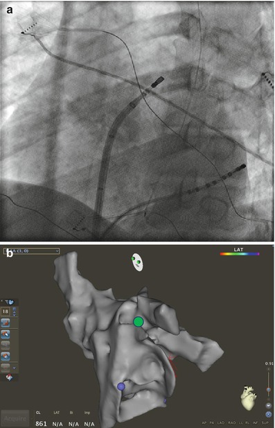
Figure 6.9
Catheter manipulation at the left atrial ridge between the LSPV and appendage. Corresponding fluoroscopic (a) views and on three dimensional electroanatomical map (b) (green circle). The ablation catheter is advanced into the LSPV. Counter clockwise anterior torque is then applied to the sheath and catheter as the catheter is pulled back into the sheath until it lands on the ridge. Further counterclockwise rotation will cause the catheter to fall into the appendage
The left atrial appendage is usually easily mapped. It is one of the most anterior structures within the left atrium. Advancing the catheter from the trans-septal site toward the LSPV with substantially more anterior torque will allow the catheter to fall into the appendage. It is important to predominately map the base of the appendage because advancing the catheter too far into the appendage can dramatically increase the risk of perforation is unnecessary for the ablation of AF. In some patients the left atrial appendage can protrude anteriorly over the mitral annulus rather than in the more common anterior superior direction. This anatomic variation should be recognized if no clear left atrial appendage is seen in the usual anatomic location.
Remote Magnetic Navigation-Guided Pulmonary Vein Isolation
Remote magnetic navigation (RMN) catheter ablation has recently been shown to be a feasible and safe technique to achieve PVI with long-term effectiveness [22, 23]. Potential advantages of RMN catheter ablation are catheter contact and stability as well as the potential for reduced risk of complications secondary to the atraumatic design of the RMN ablation catheter. We recently described our own experience with RMN for the ablation of AF in 30 consecutive patients [24]. Seventy seven percent of this small patient cohort had persistent atrial fibrillation with an average left atrial volume of 95.4 ± 33.2 ml. These patients were compared to 61 patients undergoing AF ablation with a standard PVI ablation procedure. The rates of final PVI for the individual pulmonary veins for RMN and standard PVI approaches were similar (86.7 % versus 89.8 % respectively, p = 0.67) (Fig. 6.10). However, we did find that anatomic ablation alone with RMN catheter ablation was insufficient to achieve acceptable rates of PVI. In other words, even though RMN catheter ablation may offer improved catheter stability and endocardial contact during radiofrequency application, it is still necessary to utilize an electrogram based approach with a circumferential 20 pole catheter (Lasso) within the pulmonary vein ostium to insure high rates of electrical isolation. No significant procedural complications were noted with either the standard or RMN-guided PVI.
Figure 6.10
Final individual pulmonary vein isolation rates for remote magnetic navigation and standard ablation techniques. LSPV left superior pulmonary vein, LIPV left inferior pulmonary vein, RSPV right superior pulmonary vein, RIPV right inferior pulmonary vein
Left Atrial Tachycardia Following Left Atrial Ablation for Atrial Fibrillation
As left atrial circumferential ablation has become a more effective and common therapy for atrial fibrillation [12, 25], one of the potential complicating features is the development of LA macroreentrant and focal tachycardias in the post ablation period [26, 27].
Prevalence and Incidence of Left Atrial Tachycardia Following LA Circumferential Ablation
The reported prevalence and incidence of left atrial tachycardia following LA ablation varies between medical centers. Chugh et al. reported that 20 % of patients in one series of 349 patients undergoing LA circumferential ablation had either spontaneous or induced left atrial tachycardia in the electrophysiology lab following the ablation procedure. In these patients, 55 % subsequently developed spontaneous LA tachycardia during follow-up. Overall, 24 % of patient undergoing LA circumferential ablation developed spontaneous left atrial tachycardia during an average follow-up of 394 ± 144 days post ablation. Among the 24 % of patients who developed spontaneous left atrial tachycardia during follow-up, 53 % of these had not had any left atrial tachycardia during the index ablation procedure [26]. Mesas et al. reported a lower incidence of left atrial tachycardia following circumferential left atrial ablation. In their series of 276 patients undergoing left atrial circumferential ablation, 13 patient developed left atrial tachycardia during follow-up for an approximate incidence of 4.7 %. It is not known how many patients in this series developed acute left atrial tachycardia in the electrophysiology laboratory. All of these patients underwent ablation for their left atrial tachycardia at a mean duration of 2.6 ± 1.6 months following the ablation procedure [27].
< div class='tao-gold-member'>
Only gold members can continue reading. Log In or Register to continue
Stay updated, free articles. Join our Telegram channel

Full access? Get Clinical Tree


