Cardiac Resynchronization Therapy
Mayo Clinic, Rochester, MN, USA
Heart Failure and Mechanisms of Cardiac Resynchronization Therapy
Chronic heart failure (HF) is one of the leading epidemics in the US, affecting 5 million patients overall and claiming nearly 300 000 lives annually. In the Framingham study, total mortality was 24% in women and 55% in men within 4 years of developing symptomatic HF.1 Contemporary pharmacological therapies (β-blockers, angiotensin-converting enzyme inhibitors, angiotensin receptor blockers, mineralocorticoid receptor antagonists, and statins) have yielded substantial reductions in mortality from progressive HF. Despite these advances in medical therapy, HF still carries high morbidity and mortality. The rates of rehospitalization have remained unchanged over the past decade. Each year, more than 1 million hospitalizations with a primary diagnosis of HF occur in the US and contribute more than $34 billion to medical costs for HF.2
The fundamental pathophysiology is impaired myocardial contractility in systolic HF, leading to ventricular hypertrophy and dilation. Disordered electromechanical coupling at multiple levels contributes to reduced ventricular pump function. Left bundle branch block (LBBB) is frequently accompanied by progression of left ventricular (LV) systolic dysfunction, with the consequence of delayed electrical conduction to the LV lateral wall. The loss of normal interventricular (VV) and intraventricular conduction via the His–Purkinje conduction system results in dyssynchronous ventricular excitation and contraction (Figure 9.1, left).3 This recognized ventricular dyssynchrony further reduces myocardial efficiency and cardiac output, worsening cardiac performance.
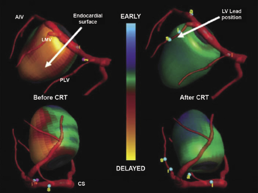
Cardiac resynchronization therapy (CRT), a non-pharmacological therapeutic approach developed more than a decade ago, resynchronizes electrical and mechanical coupling by placing leads to the right and left ventricles [via the coronary sinus (CS)] to excite the right ventricle (RV), and the LV lateral wall simultaneously (Figure 9.1, right). The acute hemodynamic benefit is apparent, including improvement in ventricular contractility and cardiac output, and reduction in mitral regurgitation and LV filling pressure. It has now been clearly proven that CRT can improve chronic LV systolic dysfunction with evidence of reverse LV remodeling.4–6 These remodeling effects include reduction in LV volumes and chamber size7 and improvement in LV ejection fraction (LVEF). At the cellular level, CRT may up-regulate β-adrenergic responses to signaling changes at the receptor and post-receptor levels, improve ion-channel function, and promote mitochondrial energy production.8–10
Indications and Patient Selection
CRT has been shown in numerous clinical trials to be an effective therapy for select HF patients. The American Heart Association/American College of Cardiology/Heart Rhythm Society (AHA/ACC/HRS) 2008 guidelines recommended CRT in patients with advanced HF [New York Heart Association (NYHA) class III or IV], evidence of severe LV systolic dysfunction (LVEF ≤35%) and evidence of ventricular conduction delay (QRS duration ≥120 ms) after failing optimal medical therapy.11 Based on recently published evidence that CRT also provides benefit to those with mild-to-moderate HF symptoms, the 2012 ACCF/AHA/HRS Focused Update of the 2008 Guidelines for Device-Based Therapy of Cardiac Rhythm Abnormalities was published in September 2012.12
The Focused Update document further stratified the class indication by using QRS duration and morphology. Among those who meet the CRT criteria for the 2008 guidelines (NYHA class III or IV, LVEF ≤35%, QRS duration ≥120 ms), patients are considered class I with a QRS duration of 150 ms or longer and LBBB; and class IIA with a QRS duration of 120–149 ms and LBBB or with a QRS duration of 150 ms or longer and no LBBB (Table 9.1). As mentioned, this modification is based on sufficient evidence that CRT is most beneficial to those with a QRS duration of 150 ms or longer and LBBB morphology, in that up to 70% of these patients may have LV electrical and mechanical delay that can be corrected by the addition of LV pacing.4,6, 13–15
| Patient population | Class | Level |
|---|---|---|
| NYHA class II, III, or ambulatory NYHA class IV, LVEF ≤35%, sinus rhythm QRS duration ≥150 ms, LBBB | I | A/B |
| NYHA class II, III, or ambulatory class IV, LVEF ≤35%, sinus rhythm QRS duration 120–149 ms, LBBB | IIA | B |
| NYHA class III or ambulatory class IV, LVEF ≤35%, sinus rhythm QRS duration ≥150 ms, non-LBBB | IIA | A |
| LVEF ≤35%, AF AVN ablation or medical rate control to allow 100% pacing Anticipated device pacing >40% | IIA | B/C |
| NYHA class I, ischemic cardiomyopathy, LVEF ≤30%, sinus rhythm QRS duration ≥150 ms, LBBB | IIB | C |
| NYHA class III or ambulatory class IV, LVEF ≤35%, sinus rhythm QRS duration 120–149 ms, non-LBBB | IIB | B |
| NYHA class II, LVEF ≤35%, sinus rhythm QRS duration ≥150 ms, non-LBBB | IIB | B |
| NYHA class I or II QRS duration ≤150 ms, non-LBBB | III | B |
| Co-morbidities and/or frailty limit survival to ≤1 year | III | C |
AF, atrial fibrillation; AVN, atrioventricular node; CRT, cardiac resynchronization therapy; LBBB, left bundle branch block; LVEF, left ventricular ejection fraction; NYHA, New York Heart Association.
Table 9.1 Recommendations for cardiac resynchronization therapy (CRT) in patients with systolic heart failure
In patients with atrial fibrillation (AF) and LVEF of 35% or less, atrioventricular node (AVN) ablation or adequate drug suppression of the ventricular rate to achieve near 100% biventricular pacing is recommended. Anticipated ventricular pacing of 40% or more may be detrimental and could be amended by CRT.16,17
The new Focused Update of the guideline recommends CRT for those with NYHA functional class II HF, i.e. mild-to-moderate HF symptoms. Patients with LVEF of 35% or less, a QRS duration of 150 ms or longer, and LBBB are class I candidates for CRT. Patients with a QRS duration of 120–149 ms with LBBB (class IIA) or those with a QRS duration of 150 ms or longer without LBBB (class IIB) are also potential candidates for CRT.5,6
In patients with asymptomatic LV systolic dysfunction (NYHA functional class I), LVEF of 30% or less, a QRS duration of 150 ms or longer, LBBB, and ischemic etiology of HF, CRT may be considered at the physician’s discretion as a class IIB indication.6
CRT has no benefit in those with mild HF symptoms (NYHA class I or II), with a QRS duration of less than 150 ms and no LBBB, and those with multiple co-morbid conditions and/or expected survival of less than 1 year.5,6,18,19
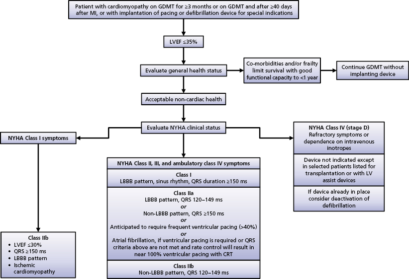
An algorithm of indications for CRT is outlined in the Focused Update document (Figure 9.2).12 The Focused Update is essentially in agreement with the Heart Failure Society of America CRT Guideline Update published in 2012.20 The latter document states that to be candidates for CRT, NYHA functional class IV patients should be ambulatory.
Patient selection criteria for CRT are summarized in Table 9.2.
|
Table 9.2 Patient selection criteria for cardiac resynchronization therapy (CRT)
CRT Implantation
There are currently three approaches to achieving LV pacing. The most commonly used is the transvenous approach, which utilizes a specially designed delivery system for cannulating the CS to permit delivery of pacing leads into the branches of the epicardial venous trees. When the transvenous approach has failed or is not available, an LV pacing lead can also be placed into the epicardial myocardium under direct visualization by using a left thoracotomy. Finally, transvenous LV endocardial pacing via trans-septal puncture has been described in limited circumstances. The hemodynamic benefit favors endocardial LV pacing; its clinical application is limited however, because chronic anticoagulation is required.21,22
Coronary Vein Anatomy
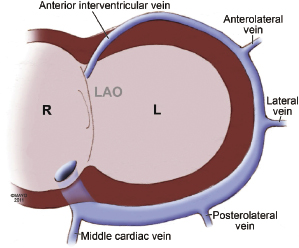
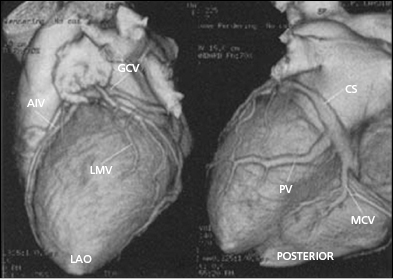
Coronary venous blood returns to the CS, which opens to the posterior septum of the right atrium. The number of coronary veins and where these veins drain into the CS differ in each patient. From the proximal to the distal CS, the coronary veins are the middle cardiac, posterior, posterolateral, lateral, anterolateral, and anterointerventricular veins, as shown in Figure 9.3. These coronary venous trees serve as the vehicle and host for LV lead placement. Most coronary veins do not exclusively collect venous return from the LV region after which they are named. The anterolateral or lateral vein may have the branches that are tributaries to the posterolateral, lateral, and anterolateral walls (Figure 9.4A,B). Approximately 60% of LV leads placed in the middle cardiac vein can be navigated to the posterolateral wall of the LV (Figure 9.4C). Overall, lateral lead position can be accomplished through multiple venous distribution, including anterolateral, lateral, posterolateral, and middle cardiac veins.23 The LV free wall is the most common region of delayed electrical activation and mechanical contraction in HF. It is critical to place the LV lead to the lateral, anterolateral, or posterolateral position to achieve biventricular synchrony. Septal lead location has been considered an unfavorable location for resynchronization.6,23 In some instances, target veins are present, but they are too small to host an LV lead or, paradoxically, are too large to achieve lead stability in the lateral location.
Coronary Sinus Cannulation
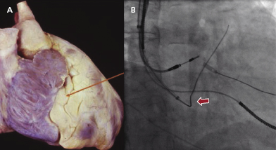
The first step is to identity a fat pad in the atrioventricular (AV) groove where the CS is located (Figure 9.5A). The fat pad appears more lucent than muscle on fluoroscopy (Figure 9.5B). There are a few ways to engage the CS:
- A 0.035-Fr guidewire, such as the SafeSheath® CSG® Worley guidewire (Pressure Products) or Radiofocus Angled Glidewire® (Terumo), can be used to engage the CS (Figure 9.5B). The wire with the angled tip (not the J tip) can be successfully placed into the CS without difficulty in some cases.
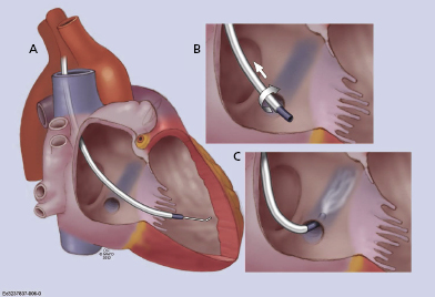
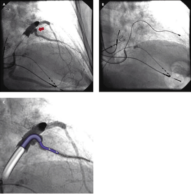
- Often, a long sheath with a sub-selecting catheter is used to engage the CS. First, the delivery set (sheath and sub-selecting catheter) is placed in the RV over the guidewire. After removing the guidewire, the delivery set is pulled back toward the CS with a counter-clockwise rotation. The sub-selecting catheter often falls into the CS ostium where a small amount of contrast injection can confirm the anatomy (Figure 9.6A–C). The sheath is then advanced into the CS over the soft sub-selecting catheter. Contrast injection, without or with a balloon obstructing the CS backflow, helps to determine the options for selecting a target vein for LV lead placement.
- When the guidewire or sub-selecting catheter is not rigid enough to support or has difficulty advancing the sheath, in some instances, a steerable ablation catheter can be used to engage the CS and support advancement along the long sheath (Figure 9.7). In this case, a straight Attain® sheath (Medtronic) or another preformed sheath may be used with the steerable catheter.
When the CS cannot be accessed despite these efforts, contrast hand injection into the right atrium or coronary angiography may be considered to facilitate visualization of the presence and location of the CS ostium in the contrast venous phase. The presence of a prominent Thabesian valve, a narrowed CS, or an obstructive valve of Vieussens may require coronary venoplasty to obtain venous access.
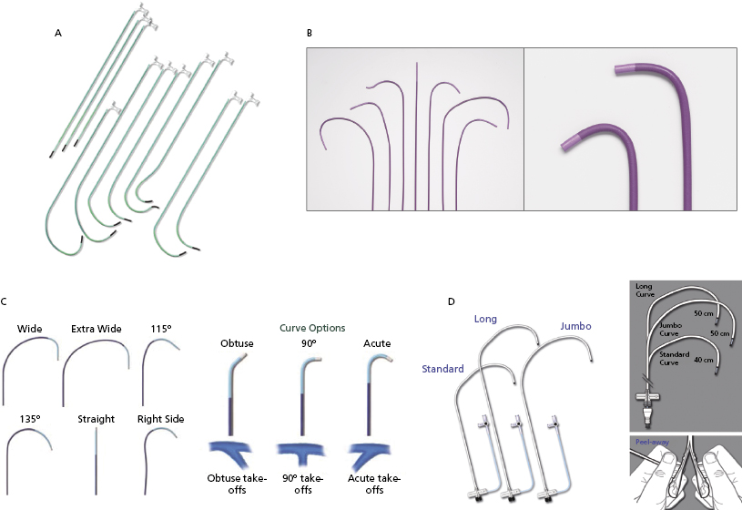
Figure 9.8 shows the variety of commercially available LV lead delivery systems. The Attain® LV lead delivery set (Medtronic; Figure 9.8A) is 8 Fr in size and available in straight and curved shapes. Various sub-selecting 7-Fr catheters are available in different shapes and angles at the tip. The Rapido® (Boston Scientific; Figure 9.8B) LV lead delivery set comes with braided catheters of various shapes and lengths, with a breakable hub that allows for simplified cutting. The CPS Direct SL® slittable outer guide catheter (St. Jude Medical; Figure 9.8C) is designed for CS access and left heart lead delivery. It is compatible with CPS Aim® inner catheters (cannulators) and the CPS Luminary® bideflectable catheter with lumen. The soft tip, which is braid re-enforced, provides torque transfer ability. Seven curve options meet the needs of various anatomies and different implanter techniques. The inner catheters have acute, 90°, and obtuse angles for selection. The SafeSheath® CSG® Worley (Pressure Product; Figure 9.8D) is designed specifically for ventricular resynchronization therapy where the right-sided chamber is considerably dilated. It has a larger lumen (9 Fr) and is available in standard, long, and jumbo sizes. The braided core provides improved torque control and its tip is radio-opaque for better fluoroscopic visualization. The long gentle throw of the Worley causes its tip to virtually fall into the CS ostium while it is being pulled back from the RV to the right atrium in counter-clockwise rotation. The sheath can be peeled away easily after the LV lead is placed. When a right-sided CRT implant is planned, the appropriate choices are right-sided delivery systems available from the Attain®, Rapido®, CPS Direct® SL, and Worley families.
Coronary Vein Navigation and Left Ventricular Lead Selection
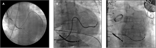
Once the CS is successfully cannulated, coronary venography may be performed to delineate the coronary venous anatomy. This is done with a standard balloon occlusion catheter and hand injection of contrast. Care must be taken to achieve a good seal within the main body of the CS in order to obtain maximal opacification of the distal vasculature. Underfilling the coronary venous system is a common mistake that may result in failure to identify potentially suitable targets for LV pacing lead placement. Occasionally, the inflated balloon occludes the ostium of a suitable branch vessel for LV lead placement; therefore, occlusive venography at multiple levels within the main CS may be needed. If complete balloon occlusion of a large CS cannot be achieved, distal occlusion with prolonged imaging may help to identify more proximal vessels by filling via collaterals. Most operators use both right anterior oblique (RAO) and left anterior oblique (LAO) views to image the CS and its branches.
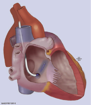
Transvenous LV pacing leads may be either stylet driven or placed with the use of an over-the-wire delivery system, similar to that used for percutaneous coronary intervention. In general, the leads are delivered most commonly over a 0.014-Fr guidewire. Larger diameter leads may accommodate a conventional stylet or a 0.014-Fr guidewire. With sheath support, the LV lead can negotiate within the target vein, as it is advanced to more distal branches. Overall, the success of LV lead placement is approximately 95%.24 Lateral veins, including the posterolateral, lateral, and anterolateral veins, are prioritized to host the LV lead. The size and length of these venous branches are usually suitable for the available types of LV leads. Most commercially available LV leads are 2.6–6.0 Fr in size (tip or body) and shaped in straight, canted, spiral, or S curve forms. A straight LV lead is usually universal, such as EASYTRAK® 2 (Boston Scientific), and is easily handled. It navigates curvature well and is suitable for torturous venous anatomy. It uses tines for fixation in the coronary veins. A canted-shape LV lead, such as Attain® Ability (Medtronic), enables the lead to be wedged in a stable position. A spiral curved LV lead, such as EASYTRAK® 3 (Boston Scientific), is often selected for a large, long venous branch. It increases the lead stability and provides good contact with the epicardium (Figure 9.9). The caveat is that the lead may be retracted and dislodged into the CS when the entire spiral segment is not well situated in the vein branch. The proximal end of the spiral curve should be anchored in the branch, not in the CS, as indicated by the arrow in Figure 9.9. The majority of available LV leads are bipolar, providing more choices for a biventricular pacing configuration. It is worth mentioning that lead stability (wedging into the distal tributary of the vein) and non-apical location need to be balanced for the final lead position. Several studies have shown that an apical LV lead location has a higher non-responder rate and less favorable CRT outcome.6,23
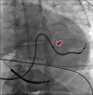
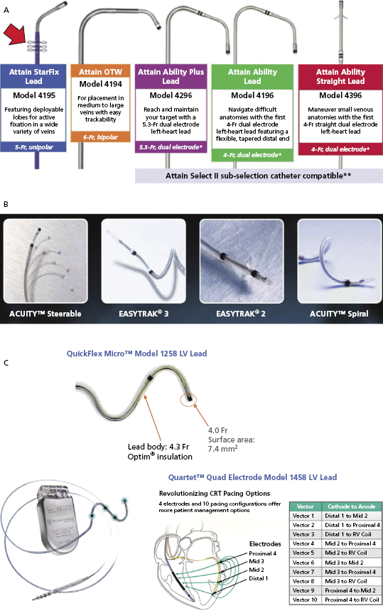
Figure 9.10A shows the Attain® LV lead family from Medtronic. Attain® Ability is 4 Fr with a canted tip, and suitable for a small venous structure. The Attain® StarFix lead has three soft lobes that can be folded to improve its stability. Figure 9.10B shows the LV leads from Boston Scientific. EASYTRAK® 3 is a bipolar lead with spiral fixation for larger vessels, while the EASYTRAK® 2 lead with tined fixation is made for smaller vessels. ACUITYTM Spiral is a small (2.6-Fr tip, 4.5-Fr body) unipolar lead with three-dimensional (3D) helical bias designed for smaller tortuous vessels. ACUITYTM Steerable LV leads have a self-retaining cant at the tip that is able to unfold within the target vein, simultaneously compressing the distal segment of the lead against the outer wall of the vein, improving fixation, and forcing the tip electrode against the epicardium, thus improving electrical contact for pacing. Figure 9.10C shows the St. Jude Medical QuickFlex MicroTM Model 1258 LV lead (4.3-Fr lead body, 4.0-Fr tip) and QuartetTM IS4 Quadripolar LV pacing lead (4.7-Fr lead body, 4.0-Fr tip, “S” curve fixation) with four electrodes and 10 potential pacing configurations. The latter provides more options to overcome phrenic nerve stimulation and high pacing thresholds, potentially resulting in less need for lead repositioning and fewer surgical revisions. It is compatible only with the Quadra AssuraTM CRT-D generator.
Assessment of Optimal Left Ventricular Lead Position
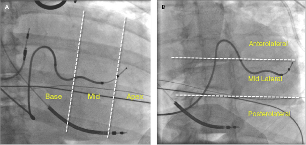
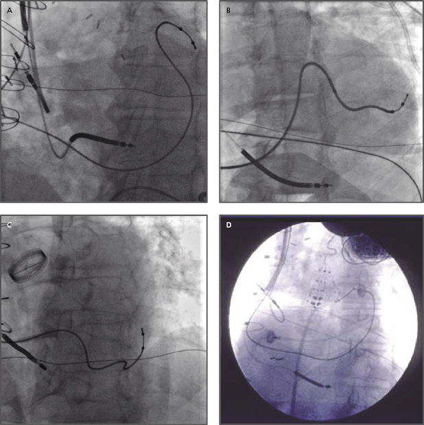
Placement of LV leads is prioritized in the lateral veins, including the posterolateral, lateral, or anterolateral veins, and the middle cardiac veins, which have tributary branches in the LV free wall, whereas the anterior interventricular vein in general is not optimal for LV pacing. At the time of lead placement, fluoroscopy is often used to assess the position of the LV lead tip, such as anterior or posterior, basal or apical location in the RAO view, or lateral versus septal location in the LAO view, as shown in Figure 9.11A,B. A greater RV–LV lead tip separation is preferred. Improved clinical outcomes are associated with LV leads positioned at the basal or mid LV lateral wall instead of the apex. Figure 9.12A–D illustrates four examples of the final LV lead position at the anterolateral, lateral and posterolateral wall, and septum (interventricular groove via interventricular vein) in the LAO view, respectively. The septal lead location is considered an unfavorable pacing site under most circumstances.
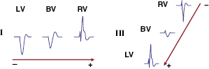
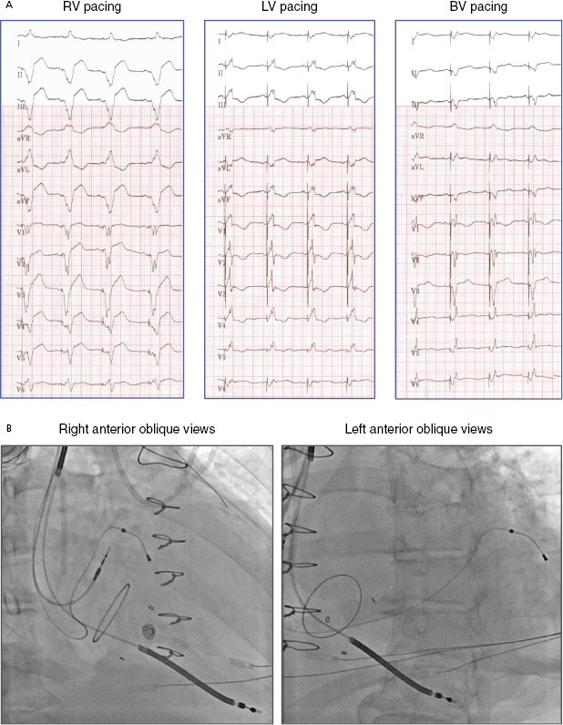
Electrocardiography (ECG) is a useful tool to assess whether LV free wall pacing is achieved. In RV pacing, ventricular depolarization propagates from right to left, commonly resulting in positive forces in lead I. In LV free wall pacing, the depolarizing vector is in the opposite direction, resulting in a negative QS morphology in lead I (Figure 9.13).25 Lead III indicates whether the pacing vector is toward an inferior (pacing from the anterior wall) or anterior (pacing from the inferior wall) direction. The RV lead is often placed at the septal apex, resulting in QS in lead III, whereas the LV pacing vector usually directs inferiorly if the lead is situated at the anterolateral or lateral wall. Yet, QS morphology in lead III may be seen when the LV lead is located posteriorly. Biventricular pacing (RV apex + LV lateral wall) produces a right superior axis as a result of fusion of RV and LV electrical axes. A qR or Qr complex in lead I is present in 90% of cases of biventricular pacing. In biventricular pacing, loss of the q or Q wave in lead I is predictive of loss of LV capture. Figure 9.14A shows an example of ECG QRS morphologies during RV, LV, and biventricular pacing with the corresponding lead positions shown in Figure 9.14B (RAO view and LAO view). The LV lead is located at the LV basal lateral wall. RV apical pacing alone has a LBBB-type and superior axis morphology (QRS duration 160 ms), whereas LV anterior free wall pacing gives rise to a RBBB-type morphology (QRS 180 ms). Biventricular pacing (QRS 150 ms, VV delay 0 ms) has an appearance of RBBB and Qr in lead I.
Assessment of optimal LV lead position is summarized in Table 9.3.
|
Table 9.3 Assessment of optimal left ventricular (LV) lead position
Management of Difficulties in Placing Left Ventricular Leads (Table 9.4)
Venous Anatomy
Multiple factors may limit placement of LV leads at ideal pacing locations. In the coronary venous anatomy, target veins may be absent, inaccessible, or obstructed. The coronary venous circulation demonstrates considerably more variability than the parallel arterial circulation (Figure 9.15). Anterolateral, posterolateral, and lateral coronary veins serve the LV free wall, while none of the anterointerventricular and only some of the middle cardiac venous branches contribute to the lateral wall.23 Up to 20% of patients may not have a vein that reaches the optimal LV free wall site for delivery of CRT. In some instances, target veins are present but too small for cannulation with existing lead systems or, paradoxically, too large to achieve mechanical fixation. Currently available leads may navigate small tortuosities impassable to larger leads.
|
Table 9.4 Management of difficulties placing a left ventricular (LV) lead
Another commonly encountered difficulty in transvenous LV lead placement is tortuosity of the target vessel take-off or main segment. These anatomical constraints can be extremely difficult to overcome and often require the use of multiple LV lead designs and delivery systems (Figure 9.16A,B). Tortuous take-offs may be overcome with the use of firm guidewires or double guidewires to straighten the vessel. Another technique is to use a sub-selecting catheter with the guide sheath, such as Renal Telescopic Braided Series (Pressure Product). The guide sheath can be advanced into the branch over the sub-selecting catheter and is able to overcome acute-angle take-off and curvature (Figure 9.16C). Thereafter, the guide sheath supports the LV lead engagement (double sheaths provide support, with the outer sheath at the CS and the guide sheath at the proximal vein take-off).
Stay updated, free articles. Join our Telegram channel

Full access? Get Clinical Tree


