Evaluation, Troubleshooting, and Management of Pacing System Malfunctions
Hunter Holmes McGuire VA Medical Center and Medical College of Virginia/VCU School of Medicine, Richmond, VA, USA
Introduction
The advanced functionality and programmability of modern pacemaker systems allow specific options to manage cardiac arrhythmias. Increasing complexity of both the mechanical (as in dual and multi-chamber devices) and software features (such as complex algorithms and pacemaker behaviors) creates a potential for increased component or software malfunction and appearance of unusual device behavior (pseudo-malfunction) that may challenge the providers. Over the last two decades, while challenges continue, technological advances have also improved the reliability and diagnostic capabilities of cardiac pacemakers and implantable cardioverter–defibrillators (ICDs). Miniaturization has allowed incorporation of increasing memory function and automatization in devices, which supports simpler device follow-up and advanced troubleshooting. In this chapter, commonly encountered problems relating to pacing in pacemakers and ICDs will be discussed.
General Considerations; Approach To Evaluate Pacemaker Function and Malfunction
Proper device evaluation and troubleshooting require the review of clinical and device history, a comprehensive, systematic clinical assessment of the patient, interrogation of the device, and review of the ancillary data. Intraoperative evaluation for diagnostic purposes is very rarely required, but is important for final confirmation of hardware abnormalities. The order of the diagnostic steps should be directed by the clinical circumstances and urgency of the problem, but in general, evaluation should start with non-invasive assessment and tests. During initial clinical encounters, some of the historical information may not be readily available and in these cases the ancillary data become even more important. Obtaining a focused medical history may help to clarify the indication of device therapy and identify prior system problems until other records become available. Co-morbidities may have significant implications regarding pacemaker programming, appropriate device selection, and risk of complications. The surgical implantation note should be carefully reviewed. The operative report should describe the indication for device therapy, vascular access site, lead type and position, device position, as well as any procedural difficulties. Device and lead parameters, including lead polarity, lead connection type, lead fixation mechanism, product manufacturer, and serial numbers should also be listed. Baseline programming parameters as well as post-implant electrocardiography (ECG) and chest X-ray are also important references. Any advisories related to the leads and device should be noted (Table 7.1). The next step is evaluation for the presence of any symptoms. While certain symptoms, such as syncope, are commonly linked to pacemaker malfunction, other less common signs may also indicate malfunction and should be looked for under appropriate clinical circumstances (Table 7.2). A focused physical exam may identify signs of heart failure and valvular abnormalities. Inspection of the jugular venous pressure may reveal the presence of cannon A waves, suggesting a loss of atrioventricular (AV) synchrony as atrial contraction takes place against a closed tricuspid valve. Presence of pectoral or intercostal muscle stimulation or diaphragmatic capture may point to mechanical malfunction. If lead integrity failure or skeletal muscle oversensing is suspected, provocative maneuvers, such as isometric arm exercise, hyperventilation, or Valsalva maneuver, may be useful to trigger abnormal function. Inspection should also extend to the device pocket to assure proper healing and look for postoperative complications such as infection or erosion. A current ECG is important to confirm the heart rhythm and presence or absence of pacing. The ECG may identify atrial and ventricular sensing or pacing abnormality, and morphology of paced atrial and ventricular complexes provides rough information on the pacing site. Review of a baseline ECG before device implantation may also be useful. Pacemaker lead position and gross lead integrity may be further evaluated by anteroposterior (AP) and lateral chest X-ray images. While analysis of the ancillary information rarely reveals all details of an abnormality, it is helpful with triaging until a device-specific programmer becomes available for further analysis.
| Pacemaker system | Pacemaker generator Manufacturer Model and serial numbers Current programming Date of implant Alert or recalls Header type Special features |
| Lead system | Manufacturer Model and serial numbers Polarity and fixation mechanism Pin type Insulation material Date of implant Alert or recalls |
| Patient | Indication for pacemaker Implant operative report Medical and cardiac diagnosis Medications History of recent medical procedures (cardioversion, defibrillation, magnetic resonance imaging, electrocautery, etc.) History of electrical current exposure, trauma |
Table 7.1 Baseline data needed for pacemaker troubleshooting
| Symptom* | Cause |
|---|---|
| Fatigue Confusion Dyspnea Orthopnea Chest pain Palpitations Presyncope Syncope | Pacemaker syndrome: Hemodynamic and neurohormonal abnormality related to ventricular pacing and/or loss of AV synchrony Loss of capture or pacing output Sensing abnormality Special algorithms Suboptimal rate-modulated pacing Arrhythmias: With or without suboptimal pacemaker programming |
| Hiccups (due to diaphragmatic stimulation) | LV pacing close to the phrenic nerve RA pacing close to the phrenic nerve RA lead dislodgement to the SVC Lead perforation |
| Chest wall/pectoral muscle contractions (due to pectoral muscle or intercostal muscle capture) | Unipolar pacing Loose set-screw Lead insulation damage Lead perforation |
*Many of the above symptoms are not specific for a pacemaker abnormality. Correlation with additional clinical and ancillary data is required to make the diagnosis.
AV, atrioventricular; LV, left ventricular; RA, right atrial; SVC, superior vena cava.
Table 7.2 Symptoms suggestive of pacemaker abnormality
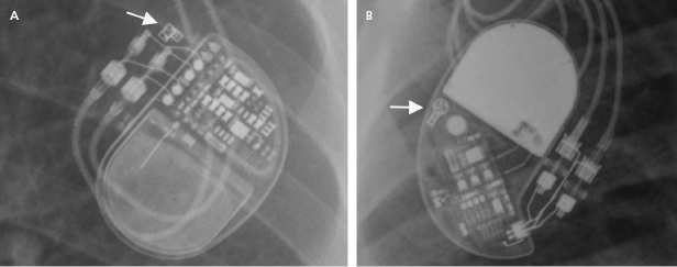
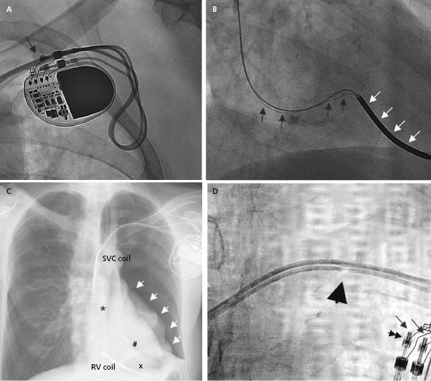
The programmer is required to retrieve information from the device memory and test the pacing system. It is therefore essential to know the manufacturer of the device in order to perform a full evaluation. A manufacturer’s information may be retrieved from the operative report or from the device identification card that is mailed to the patient following an implant. If these are not available, the radiographic identifier of the pulse generator (Figure 7.1) on a chest radiograph or pacing response to magnet application over the pacemaker (magnet response) may help to narrow down the device manufacturer. An X-ray image showing the profile of the device may also provide additional clues.1 If all these efforts fail, technical service representatives of the device companies (current major device manufacturers in the US include Biotronik, Boston Scientific, Medtronic, Sorin, and St. Jude Medical) may be able to retrieve the patient information from their implant database. Technical services may also assist with interpretation of the device interrogation and provide additional information about the leads, pulse generator, and certain device- and manufacturer-specific algorithms.
Differential Diagnosis of Device Malfunction
Pacing system malfunctions may be categorized according to ECG manifestations, including abnormal sensing, lack of pacing or of capture, and abnormal or unexpected rate of pacing. In broader terms, pacemaker malfunction also includes symptoms associated with the pacing or pacemaker programming, or complications from the pacemaker system. Malfunctions may also be divided according to the particular cause, which includes mechanical abnormalities, programming abnormalities, and extrinsic/external causes. In clinical practice, malfunction is usually suspected based on abnormal ECG or symptoms. Latent abnormalities may also be diagnosed from stored device data and proper action may halt an impending clinical problem. Ultimately, the particular cause is determined following correlation of all ancillary information with the interrogated device data.
Abnormalities in the Mechanical Components of a Pacing System
A pacing system is comprised of a pulse generator and the pacemaker lead(s). The pulse generator, which houses the battery and electrical circuitry, is hermetically sealed and connected to the pacemaker leads through the header. The pacemaker lead pins are secured in the header with one or two set-screws during the implant procedure. The leads maintain a connection to the cardiac tissue by either an active screw mechanism or passive fixation. The pacemaker leads consist of one or more conductors surrounded by insulation material. In a bipolar lead, the conductors connect the tip and ring electrodes to the terminal pin, whereas in a unipolar lead only a tip electrode is present and the can serves as the anode (Figure 7.1 and Figure 7.2). The ICD leads are more complex structures incorporating, in addition, one or two coils for high-voltage defibrillation. These additional components make lead engineering more difficult and are likely major contributors to a poorer long-term lead survival compared to that for pacemaker leads. The electrical circuit of a pacer system is completed by the tissue between the anode and cathode. The distance between the anode and cathode is the major difference between a unipolar and bipolar system in terms of sensing characteristics and current and energy requirement to capture the myocardium. A larger distance in a unipolar system predisposes to sensing far-field signals from cardiac or non-cardiac sources. Pacing impedance is lower during unipolar pacing compared to bipolar pacing in the same system. Any defect in the integrity of the lead and pacemaker header assembly may result in the introduction of noise and cause sensing abnormality or divert pacing current away from the myocardium with resultant capture failure.
Pulse Generator Hardware and Software
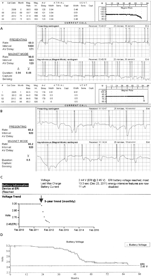
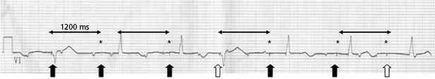
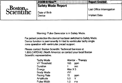
A predictable failure of any current pacer or ICD system is related to battery depletion, which is the most common reason for device explantation.2 One of the goals of regular device follow-up is to ascertain that there is adequate battery capacity to maintain appropriate device function. Among the several challenges of battery engineering are the constant efforts to minimize device (and battery) size, yet maximize longevity in a very reliable manner. In addition, in order to allow adequate time to diagnose battery depletion and schedule generator replacement, battery depletion has to follow a very predictable pattern. For the purpose of cardiac pacing, the characteristics of lithium–iodine batteries have been optimal and have been utilized for decades with great reliability. Battery voltage remains relatively flat during much of the device’s lifetime, with decline only close to end of service. Battery impedance on the other hand increases continuously, with a very rapid rise as battery depletion approaches. Impedance is therefore a better overall predictor of battery longevity at any given time point. Manufacturers differ in whether they express battery parameters in numerical or graphical fashion, but battery status is one of the key parameters that is followed in the clinic. Application of a magnetic field over a pacemaker (clinically by placing a special donut-shaped magnet) results in a device-specific magnet response. This response may be observed during clinic follow-up or during trans-telephonic monitoring (TTM). In most pacemakers, magnet application results in asynchronous pacing at a certain rate (except for rare circumstances when a different special magnet function is programmed “on”). As the battery approaches end of service, the magnet-activated pacing rate gradually decreases or remains stable in some generators until the battery reaches elective replacement indicator (ERI) status. At this point, a specific model or company-specific magnet rate indicates that the device is nearing end of service (Figure 7.3). At ERI there is an additional 3 months’ battery support before the device reaches end of life (EOL). At EOL, device reliability is not guaranteed and erratic behavior may be observed (Figure 7.4). As ERI may also trigger a change in pacing mode (rate response turned “off,” switch to single chamber VVI mode); in rare patients, clinical decompensation may occur even as ERI is reached (Figure 7.5). Increasing availability of Web-based remote home monitoring has revolutionized patient follow-up and this technology will likely completely replace TTM in the near future.3
ICD batteries are designed differently from pacemaker batteries in order to support standard pacing requirements (1–20 μJ per pacing pulse) and deliver rapid charge to high-voltage capacitors (up to 30–40 J) for defibrillation or cardioversion therapy of tachyarrhythmias. These tasks are achieved more efficiently with currently used lithium–silver vanadium oxide- or lithium–manganese dioxide-based batteries. The discharge curves of these batteries vary based on the composition material and also differ from those of pacemaker batteries. It is important to understand the individual variations in order to make informed decisions during follow-up. Assistance from the technical service at the device company may be helpful in unclear situations. In ICD generators, battery voltage and capacitor charge time is used most commonly to follow the battery status.
While reliability of pacemaker and ICD generators continues to improve, random system failure or mechanical (such as battery, circuitry, header, wiring, etc.) or software design flaws continue to occur, as has been seen in recent advisories.4 Depending on which particular component is affected, inappropriate pacing behavior, battery or wiring short with lack of pacing or defibrillation, or accelerated battery depletion may result (Figure 7.3C). Early battery depletion may be caused by suboptimal device programming or lead/patient-related events (exit block, high pacing threshold, frequent defibrillation therapy in ICDs). Other causes of generator failure or malfunction may be suspected based on clinical circumstances, such as recent mechanical trauma to the device site, exposure to significant electromagnetic interference (EMI; especially in hospital settings, such as electrocautery, MRI scan, TENS), or radiation (diagnostic or therapeutic). While EMI has caused system failures in early devices, these types of serious events are much less common with modern pacemakers and ICDs due to advanced filtering and shielding, and increased awareness of these potential interactions.5 EMI may cause temporary changes in pacemaker or ICD behavior and trigger a reset or a partial reset of the device. These are fallback safety settings that are activated in the event of suspected software or hardware malfunction. Most commonly, a change in bradycardia programming (and/or tachycardia programming in ICDs) or loss of stored data occurs. The programming changes are usually reversible, but a generator change may be required in rare instances when changes are non-programmable (Figure 7.6). Direct or scattered radiation may affect the device circuitry and cause various levels of reset. Direct radiation over the device may cause permanent damage to the circuitry. If the device-specific safety dose is exceeded, the reliability of the device may be impaired and the generator has to be replaced. The radiation exposure for the device needs to be calculated, especially when therapeutic radiation is applied close to the device site. The maximum tolerated radiation dose for a particular device is available from the manufacturer. If the planned radiation path is close to or over the device, the generator may need to be repositioned before treatment, particularly in pacemaker-dependent patients. The mechanism of radiation-induced changes is multifactorial. Modern devices utilize complementary metal oxide semiconductor circuitry (CMOS). Radiation may induce ionization in CMOS with build-up of a charge.6 The time course of these changes and possible consequences are variable, and include increased current drain and shortened battery life or changes in sensing. Scattered radiation may also affect the random access memory (RAM) and result in errors in device function or data storage. RAM is increasingly used in more complex ICDs, but also in newer generation pacemakers.
Software abnormalities had been common reasons for device advisories in the past. The increasing sophistication of the device circuitry and memory have increasingly allowed non-invasive postoperative software upgrades via the programmer, and the clinical consequences of software anomalies in recent years have been less significant. An example of software upload includes the update of Medtronic ICDs with the Lead Integrity AlertTM algorithm in order to minimize the risk of inappropriate ICD therapies in the event of a lead fracture. This software was retro-fitted to several earlier classes of Medtronic devices.7 As software-specific information is proprietary, providers need to rely on information from the manufacturers about any updates or to confirm abnormalities.
Failure of pacemaker circuitry or complete depletion of the battery results in system failure and inability to interrogate the device. If communication with the device cannot be established, several possible confounders need to be ruled out before a generator change is contemplated. First, an environmental factor that may affect the communication with the device, such as EMI [as may be seen in a patient with a left ventricular (LV) assist device], or a malfunctioning programmer has to be excluded. As part of the evaluation process, the manufacturer of the device has to be ascertained, as discussed above, to make ensure that the proper programmer is used for interrogation. This is critical for assessing a new patient, but may also be an embarrassing oversight in a patient who is normally followed in the device clinic but had a device exchange or upgrade performed in another facility between visits.
Leads
Pacemaker and ICD leads are commonly referred to as the Achilles heel of the pacer/ICD system as they remain the main source of mechanical failure. Starting at the implantation procedure and over the lifetime of the system, leads are exposed to significant chemical and mechanical stress in the hostile intravascular environment. The restricted space at the intersection of the first rib and clavicle may cause additional stress, and this is the site where subclavian crush injuries develop. Lead-to-lead and lead-to-can interaction as well as tight anchoring sutures are other common mechanical points for potential lead failure. Lead-to-lead interactions may also occur between the leads as they make their way to the heart in the vascular system. Repetitive stress due to friction, pressure, and cyclical repetitive movement may result in lead insulation defect or fracture of the conductors. Certain pacemaker or ICD leads are more prone to develop structural failure for various reasons, such as defects in the design or manufacturing of insulation material, type of insulation material, or other parts of the lead assembly. Long-term survival data for individual leads are available from the performance report of the manufacturers. Lead failures are notoriously underreported and it is difficult to know the true incidence of this problem. In case there are concerns about lead reliability, advisories are initiated by the manufacturer or Food and Drug Administration (FDA) to inform clinicians and assist with clinical decision-making. While the reliability of pacemaker leads has improved over the last decades, two major advisories drew attention to design failures and risk of premature lead degradation in certain ICD leads, affecting tens of thousands of patients (Sprint FidelisTM, Medtronic in 2007; and RiataTM, St. Jude Medical ICD leads as well as LV leads from St. Jude Medical, 2011).8 Review of recommendations about the management of these advisories is beyond the scope of this chapter but in general, an individualized approach is recommended with enhanced surveillance. Routine invasive interventions are rarely beneficial or advised for prophylactic purposes.
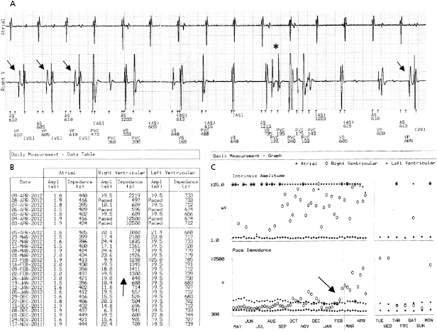
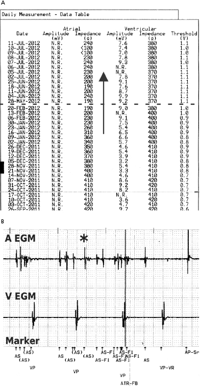
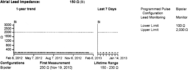
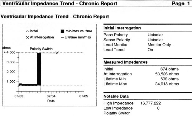
In general, abnormalities in lead insulation manifest as decreased lead impedance, whereas conductor fracture is associated with increased lead impedance (Figure 7.7 and Figure 7.8). Insulation or conductor failure may cause noise, oversensing, or failure to capture. The normal lead impedance values usually vary between 300 and 1800 Ω depending on the particular lead characteristics, but remain relatively stable following the lead maturation period. Out of range values would not necessarily mean abnormal lead function (Figure 7.9). On the other hand, significant variation in lead impedance, even if it is within the range of “normal values,” should raise concerns about possible lead failure.9 Sub-clinical mechanical abnormality may present with sudden, erratic change in lead impedance in the lead trend data or non-physiological noise may be recorded as an arrhythmia event (Figure 7.7). Web-based remote or in-situ alert notifications are increasingly used to warn patients and providers if lead impedance parameters fall outside of a programmable, predetermined range. Lead failure in a pacemaker system may result in oversensing and lack of or inappropriate pacing or lack of capture. In certain pacemakers, automatic polarity switch (from bipolar to unipolar) takes place if lead impedance values reach an out of range value. This safety feature may help to re-establish pacing if only the ring electrode circuit is damaged (Figure 7.10).
In ICD patients, noise and oversensing may present with inappropriate ICD therapies or dizziness and syncope due to oversensing and pauses. In some newer generation ICDs, a near-field or sensed intracardiac electrogram (EGM) is correlated with a far-field EGM to rule out oversensing of non-physiological signals (SecuresenseTM, St. Jude Medical; SmartshockTM, Medtronic). A special algorithm, developed by Medtronic, monitors lead impedance change, VT episodes in the non-physiological range, and non-physiological ventricular-sensed events (VV intervals in the range of 120–130 ms that are too closely coupled to represent physiological ventricular depolarization), and this technology has been helpful to identify impending lead integrity failure before any clinical event and reduce the risk of inappropriate ICD therapies.7 Any suggestion of lead integrity failure has to be taken very seriously, especially in ICD leads or in pacemaker-dependent patients, as the functionality of the lead may change very rapidly and failure to act on it in a timely manner may have catastrophic consequences.
In broader terms, lead failure may be seen with mechanically intact leads when fixation to the heart is suboptimal, such as in the case of micro- and macro-dislodgement or lead perforation. Macro- dislodgement is suspected based on alterations in pacing parameters and change in lead position seen on imaging studies (mainly chest X-ray). A change in the paced ECG morphology may also be evident following significant ventricular lead migration. Atrial lead dislodgement to the ventricle may mimic switched lead pins in the header. Micro-dislodgement is suspected when pacing parameters change (decreased sensing, increased pacing threshold, change in lead impedance, or a combination of these) within the first days to weeks following implantation, but without a noticeable change in lead position based on X-ray appearance. It is important to remember that during normal lead maturation, an inflammatory reaction takes place in the myocardium near the lead tip. This may result in an increase in capture threshold and decrease in sensing, and can be expected to resolve within several weeks. Almost all contemporary transvenous leads now have steroid-eluting tips, which have markedly reduced the incidence of significant tissue reaction. Once the healing process is complete, some degree of fibrosis develops at the lead tip contact site and when this process is excessive, permanent exit block and sensing abnormality may develop. Exit block usually develops in the chronic stage, weeks to months after implant. Differentiation between exit block and micro-dislodgement is difficult, especially if the abnormality is identified weeks to months after implant. Lead dislodgement may be due to inadequate fixation to the cardiac tissue, inadequate lead redundancy, loose fixation of the lead in the suture sleeves, or patient-related causes (such as non-compliance with activity or Twiddler’s syndrome). It is important to identify the mechanism of failure (if possible) in order to minimize the chance of the same problem occurring over again. Lead repositioning would resolve the problem with dislodgement, but exit block is related to tissue reaction and a similar response may develop at the new implant site. The decision to manage lead abnormalities invasively or non-invasively is dependent on the clinical circumstances, such as the lead affected, urgency of need for pacing, and degree of change in parameters.
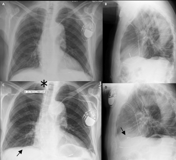
Acute lead perforation usually presents as a hemodynamic catastrophe in the perioperative period and usually requires emergency pericardiocentesis and lead repositioning. Subacute and chronic lead perforation may cause pericarditis, pericardial effusion, pneumothorax (may be seen with right atrial lead perforation), and pectoral muscle stimulation, and are associated with changes in pacing, sensing, and impedance values. In the case of gross lead perforation, chest X-ray is very helpful (Figure 7.11). In these cases, complete loss of capture and sensing may be seen. Micro-perforation may be suspected if the unipolar tip pacing threshold is significantly higher than the ring threshold in appropriate clinical settings. If high output pacing causes pectoral muscle stimulation, the possibility of perforation should be considered. Advanced imaging studies with computed tomography (CT) scan or echocardiography are of limited value in evaluating micro-perforation because of streaming artifact from the lead tip, but may be of diagnostic value.10 In most cases, lead revision is required to correct the problem.
Lead-to-lead interaction may cause chatter and oversensing when the tip or ring electrode collides with other intracardiac leads during the cardiac cycle. This is best avoided by paying meticulous attention to lead positioning when more than one lead is present in the cardiac chamber. X-rays in two orthogonal views should document that the lead tips and electrodes are ideally at least 1 cm apart (Figure 7.2).
Inadequate connection of the lead pins (from using devices with non-compatible headers, connecting to the wrong pinhole, or improper tightening of the set-screw) is a cause of a completely avoidable mechanical malfunction. Another usually reversible abnormality may be seen when an air bubble remains entrapped around the lead pin following securing of the lead in the header during implantation. Once the air evaporates from the chamber (generally within a few hours to days), the noise usually subsides. Rarely, re-operation may become necessary if sensing or pacing abnormality persists.11 Careful implantation techniques may help to reduce the risk of future mechanical problems.
Radiographic Imaging of Pacer Systems
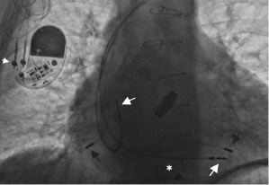
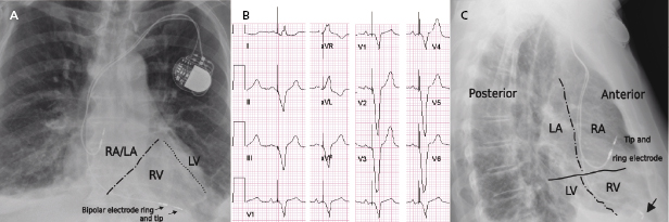
Radiographic imaging is a routine part of the clinical assessment following a device implant and in chronic settings when clinical questions arise. As the left cardiac chambers are positioned in a posterolateral orientation relative to the right chambers, a PA projection alone is not sufficient to adequately assess lead position (Figure 7.12). Two commonly used perpendicular X-ray projections include posteroanterior (PA) and lateral projections during outpatient follow-up, and right and left anterior oblique views during implant. Inadvertent lead placement in the left chambers may easily be missed unless lateral projections are included in the evaluation. Besides providing information on lead position, chest X-ray also helps to identify the number and type of leads present (such as unipolar or bipolar, active or passive fixation, pacemaker or ICD lead; Figure 7.2). Company-specific radiographic markers of the pacemaker may be identified and adequate connection of the lead pins confirmed (Figure 7.1). Certain lead abnormalities, such as integrity failure or fracture, may also become apparent on an X-ray and X-rays are the primary screening tools for certain complications related to the pacing system (Figure 7.13).
Electrocardiographic Manifestations of Pacer Malfunction
Interpretation of the Electrocardiogram
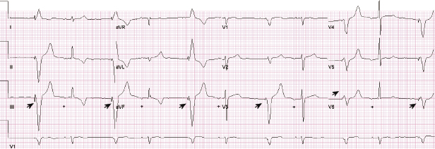
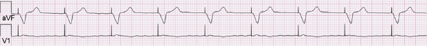
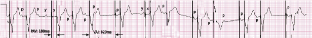
Abnormal pacer function may be suggested by a telemetry strip or a 12-lead ECG and a consultation at pacemaker clinics is common for this reason. When one faces a challenge in analyzing an ECG strip, the first task is to identify the intrinsic and paced cardiac complexes and the underlying atrial rhythm. It is often a challenge to identify P waves or pacing artifacts, and occasionally even QRS complexes may be hard to recognize, especially from a single-lead ECG. Multiple ECG leads should be examined if there is any uncertainty. It is important to look for clues such as the presence of a T wave despite a “missing” QRS complex, as may be the case when the QRS vector is small or relatively isoelectric in a particular lead (Figure 7.14). The isoelectric QRS vector is occasionally seen in TTM strips. The next task is to search for pacing artifacts and establish their relationship and timing to intrinsic complexes (P wave, QRS). Once pacing artifacts are identified, electrical capture of the relevant cardiac chamber has to be evaluated (i.e. pacing artifact consistently followed by P wave or QRS complex; Figure 7.15). Based on the timing of the pacing spikes, the base rate, AV interval, ventriculoarterial (VA) interval, and AA interval should be determined if possible. Measurement of these basic pacing intervals on a 12-lead ECG and their correlation with intrinsic cardiac events often clarify a device behavior without further need of device testing. It is important to note that digital ECG recording systems may reduce or eliminate pacing artifacts due to filtering or assign pacing artifacts spuriously. Electrical artifacts may also be recorded as signals from non-cardiac devices; therefore just like in any other test, ECGs should be interpreted in the clinical context (Figure 7.16).
Stay updated, free articles. Join our Telegram channel

Full access? Get Clinical Tree


