Techniques of Pacemaker Implantation and Removal
Johns Hopkins University School of Medicine, Baltimore, MD, USA
Introduction
A permanent pacing system consists of a pacemaker generator and one or more leads that connect it to the endocardial or epicardial surface of the heart. Considerable evolution in technique and hardware has occurred over the past several decades, which has simplified the implantation procedure. Associated with this evolution has been a miniaturization of the power source and circuitry of the generator, and near-universal use of smaller and more flexible transvenous leads.
Compared with such tasks as optimization of programming and interpretation of complex pacemaker electrograms, the implantation of a modern pacemaker may now be the least challenging aspect of cardiac pacing. However, it would be inappropriate to create the impression that all pacemaker implantation is easy. Implanters should be dedicated to lifelong continuous improvement of their skills and knowledge, learning from their own challenging cases as well as those of colleagues.
In this chapter, transvenous single and dual chamber pacemaker implantation is examined from a broad perspective that emphasizes the practical considerations influencing the safety and efficacy of this procedure. In addition, the indications for and methodology of removing implanted pacing devices are reviewed.
Physician Qualifications
Pacemaker implantation is performed by physicians from a variety of specialties, including cardiothoracic surgeons, non-electrophysiology cardiologists, and electrophysiologists. Formal training in the implantation of arrhythmia management devices is most extensive in clinical cardiac electrophysiology fellowship programs. Despite the growth in numbers of trained electrophysiologists, many non-electrophysiology cardiologists continue to implant pacemakers either alone or as part of a surgical team. In addition, many electrophysiologists and cardiologists call upon their surgical colleagues for assistance in more complicated implantations, such as submammary or subpectoral dissections.
Procedural success and safety are determined in large part by the skill and experience of the operator. Although the degree of “surgery” required for a routine transvenous implantation is modest, good surgical technique is essential. Experience is also necessary to ensure proper positioning of leads so that optimal stability and long-term performance are obtained. A physician wishing to implant pacing systems independently should perform a sufficient number of procedures under the supervision of an accomplished operator to gain the skill and confidence necessary for independent work.
The minimal number of cases to credential a physician depends on the physician’s prior familiarity with intravascular catheterization, surgical technique, and knowledge of the principles of pacing. This experience should include single and dual chamber systems, and use of both the subclavian/axillary and cephalic approaches for venous access. In addition to this initial training experience, an adequate number of implantations should be performed over time to maintain a level of proficiency. Guidelines for training in pacemaker implantation have been published that may serve as a general model.1 The guidelines acknowledge the special training necessary for those physicians seeking credentials in biventricular pacing, defibrillator implantation, and lead extraction. Because fluoroscopic imaging is a necessary component of the implantation process, knowledge of the basics of radiation physics and safety is required to minimize risk to the patient, operator, and laboratory personnel.
Specialty assistance may be anticipated before a procedure in some cases, and appropriate consultation should be obtained. Implantation procedures are generally performed under moderate sedation, but on occasion there may be a need for the support of an anesthesiologist. Implanting physicians should be familiar with the principles of moderate sedation and the particular institutional guidelines under which they operate, including the acceptable drugs (dosages, reversibility) and the necessary support personnel, monitoring equipment, and recovery procedures.
Quality assurance has become a necessary part of every hospital’s activities, and surgical operations and the physicians who perform them are most thoroughly scrutinized. It is the responsibility of all physicians to be conscious of the quality of their work; those in administrative positions should ensure that proper databases are maintained and performance evaluations are carried out. The objective of these practices is improved quality of care.
Logistical Requirements
The logistical requirements for pacemaker implantation are relatively modest. The procedure may be carried out in an operating room, a catheterization laboratory, or a special procedure room with no compromise of success rate or difference in complications. Implantation in the cardiac catheterization laboratory has been shown to result in a significant reduction in the cost and length of hospital stay compared with implants in the operating room by surgeons. This is probably due to the increased flexibility in scheduling in the catheterization laboratory, as well as the use of conscious sedation administered by catheterization laboratory personnel instead of anesthesia staff.
The procedure room should be adequate in size and well lit, and it should comply with all the electrical safety requirements for intravascular catheterization. The radiographic equipment should function within accepted guidelines, and appropriate radiation shielding should be available and used. The room should have appropriate temperature control and ventilation for sterile procedures.
In addition to the operator, the staff should include qualified individuals to monitor the electrocardiogram (ECG) and assist with the imaging equipment. A nurse is required to prepare and administer medications. Often a representative of a pacemaker company is present to provide technical assistance, such as with operating the pacing system analyzer or device programmer. These individuals may be a valuable source of information, but should not be considered a substitute for a nurse or laboratory technologist during the implant procedure. Laboratory personnel should also be trained in adherence to rigorous sterile techniques.
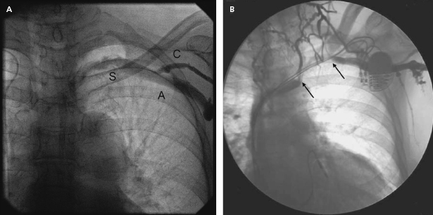
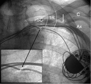
An adequate imaging system is an important requirement of the pacemaker laboratory. The fluoroscopy equipment may be portable or fixed, but must be capable of rotation so that oblique and lateral views of the areas of interest (which may extend from the neck to the groin) can be obtained. A mechanism for magnification is helpful for situations such as confirmation of extension of the helix of active fixation leads, lead removal procedures, and the identification of problems such as fracture of a conductor or “J” retention wire. Digital acquisition and storage capabilities have proven to be advantageous and are widely used. Such technology can be used to road-map or superimpose real-time fluoroscopy on a stored image. Thus, one can bring up a stored image of the subclavian venogram to document the vein patency and to serve as a target for an exploring needle being advanced under fluoroscopic monitoring (Figure 5.1).
The use of pulsed digital fluoroscopy can reduce radiation exposure to the patient and operator, and should be used whenever possible. Frame rates of 7.5 fps are usually adequate for pacemaker implantation, and newer systems may use as little as 3.75 fps. Newer imaging systems may also increase patient safety by providing on-line dose measurements that more accurately reflect radiation exposure than does total fluoroscopy time. The patient table should be flat, radiolucent, and configured in such a way that the operator may work on either side of it. Movement of the imaging system about the support should be unhindered.
It is essential that the ECG be continuously monitored; a simultaneous multilead display that is easily visualized is preferable in order to assess paced QRS axis and morphology. There should be an ability to obtain a hard copy of the monitored rhythm strip as well as a 12-lead tracing if necessary. Leads placed on the chest or back should consist of radiolucent electrodes and wires. The patient should be connected via radiolucent transthoracic electrode patches to an external defibrillator capable of transcutaneous pacing, cardioversion, and defibrillation in case an arrhythmia develops during the procedure. Arterial blood pressure and pulse oximetry should be monitored throughout the procedure. A portable ultrasound device may be helpful in identifying vascular structures and provide guidance for venous access.
The surgical instruments required for the procedure depend on the demands of the particular procedure and operator. A pacemaker tray may be derived from the hospital’s surgical cut-down set and supplemented in accordance with the specifics of the case. Add-ons include tear-away vascular introducer sets, appropriate cables to connect to a pacing system analyzer (PSA), suction, and electrocautery. The operator should be familiar with the guidelines for electrocautery use to ensure safety, particularly when oxygen is being administered.
An adequate supply and variety of pacing hardware should be available, including not only pacemaker generators and leads, but also sheaths, stylets, and lead adaptors. It is good practice to have at least two of every necessary item on hand in case of accidental damage or loss of sterility.
The PSA measures a variety of pacing parameters (capture and sensing threshold, lead impedance, electrograms, slew rate) that assess the adequacy of lead position and integrity. A direct digital readout and the capability to print a hard copy are desirable. Some manufacturers have consolidated products by configuring their programmers to act as PSAs when necessary. Equipment necessary for emergency pericardiocentesis, chest tube insertion, and temporary endocardial pacing must be at hand, and it is advantageous to have prompt access to a two-dimensional echocardiography machine. A crash cart containing resuscitative supplies (including those necessary to establish endotracheal intubation), an adequate supply of all appropriate drugs, and experienced staff should be readily available.
Assessment of the Patient
The implantation process begins with a thorough evaluation of the patient. This should include reviewing medical records, obtaining a pertinent history (including current medications, especially anticoagulants and antiplatelet agents, and previous reactions to drugs and contrast media), performing a physical examination, and acquiring the basic laboratory tests.
The indication for pacing should be documented and characterized in accordance with the American College of Cardiology (ACC)/American Heart Association (AHA) guidelines.2 In some situations, it may be reasonable to offer pacemaker therapy for conditions in which the indication for such therapy is controversial and evolving, such as recurrent neurally-mediated syncope with a prominent cardioinhibitory component. Documentation of the indication for a pacemaker implantation should be made in the patient’s chart and supported by a relevant ECG tracing.
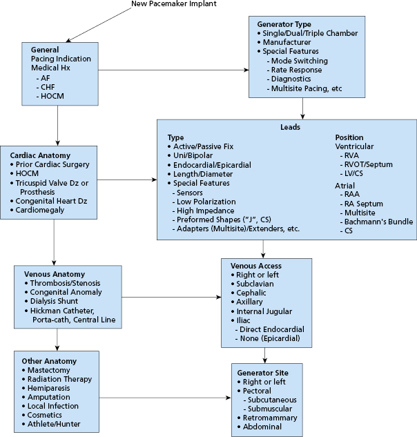
Consideration of the type of pacing system to be used should be part of the patient assessment. The choice of mode of pacing (e.g. atrial; ventricular; single chamber, dual chamber, biventricular) is made on the basis of the underlying conduction disturbance, the present and future potential need for pacing, and the hemodynamic and functional status of the patient.3,4 Other factors that might influence the method of implantation, the operative site, or the type of hardware needed should be considered before the procedure. Examples include: the need for an unusual vascular approach (e.g. iliac vein) or an epicardial lead system in a patient with a previously documented venous anomaly; and employment of an active fixation ventricular lead in a patient with severe tricuspid regurgitation or corrected transposition of the great vessels. These factors comprise an array of choices that should be carefully considered before the patient enters the procedure room (Figure 5.2). Thorough preparation is essential to minimize problems at implantation.
Special Issues
Several issues in patient assessment and preparation merit special consideration (Table 5.1).
| Infection |
| Kidney disease |
| Anticoagulants and antiplatelet agents |
| Subclavian vein anomalies |
| Prior mastectomy |
| Tricuspid valve disease/prosthesis |
| Risk for asystole (left bundle branch block, complete atrioventricular block) |
| Prior central venous lines |
| Prior clavicular fracture |
Table 5.1 Special issues in the assessment of the patient who requires cardiac pacing
Infection
Implanters are frequently asked to implant permanent pacemakers semi-urgently in hospitalized patients with co-existing infectious issues. Decision-making regarding the timing of pacemaker implantation in these patients can be complex, and depends on the site of the suspected or documented infection, concern for bacteremia, and indication for cardiac pacing. For example, a patient with complete atrioventricular (AV) block who has asymptomatic bacteriuria with no fever and normal white count can usually be implanted with minimal delay while treating the potential lower urinary tract infection. On the other hand, a patient with bacterial endocarditis and mildly symptomatic sinus node dysfunction is best completely treated and cure proven prior to implantation. Patients with pneumonia without bacteremia can usually be implanted after antibiotic therapy has rendered them afebrile for 2–3 days.
A special population comprises patients with an existing infected cardiovascular implantable electronic device (CIED) that is to be removed. Although temporary pacing may be immediately required for dependent individuals, guidelines for re-implantation of a permanent system require evaluation for infective endocarditis and negative blood cultures. In general, the minimum duration between extraction and re-implantation is 3–14 days.5 In such difficult cases, consultation with infectious disease colleagues regarding duration of antibiotic therapy may be helpful. In considering the timing of implantation, the risk of pacemaker infection needs to be balanced against the risk of delaying pacemaker therapy and of prolonged hospitalization awaiting “ID clearance.”
Kidney Disease
Patients with chronic kidney disease also merit special consideration. For the patient with end-stage renal disease (ESRD) on dialysis, pacemaker implantation and overnight observation must be coordinated with the outpatient dialysis center to ensure that dialysis is not disrupted. Implantation is usually scheduled on a non-dialysis day and dialysis is scheduled the next day, either as an inpatient on the morning of discharge or at the outpatient center in the afternoon. In general, implantation should be performed on the side opposite to the functioning dialysis access site, due to elevation of venous pressure on that side (raising risk of bleeding) as well as risk of loss of use of the dialysis access site should subclavian vein stenosis or occlusion result from the pacemaker insertion. In cases where the ipsilateral pectoral site must be used, some advocate use of the supraclavicular or internal jugular approach to minimize these risks. Because the risk of infection is higher in ESRD patients, especially in those receiving catheter-based hemodialysis, some thought might be given to the implantation of an epicardial lead system.
For patients with lesser degrees of renal dysfunction (determined by estimated creatinine clearance), the main issue is whether use of intravenous contrast is anticipated, and if so at what dose. Upper extremity venography can usually be performed with 10–20 mL of diluted contrast, which generally poses little risk. Patients undergoing biventricular pacemaker implantation may occasionally require as much as 80–100 mL of contrast when there is difficulty engaging the coronary sinus (CS) or identifying a suitable tributary for lead placement. In general, we favor use of isosmolar, non-ionic contrast for such patients and make every effort to minimize total contrast dose, using diluted contrast wherever possible. Recent consensus guidelines for prevention of contrast-induced nephropathy have emphasized use of pre- and post-procedure intravenous hydration with normal saline or sodium bicarbonate.6 Other agents, such as N-acetylcysteine (NAC), have not been found to be uniformly effective for this purpose.
Anticoagulants and Antiplatelet Agents
Many patients requiring pacemaker implantation take oral anticoagulants for a variety of reasons, including atrial fibrillation, mechanical heart valves, and prior venous thromboembolism. Their peri-implant management is often complicated and related to their indication for anticoagulation. There are three general options. The traditional approach has been to convert the patient to intravenous unfractionated heparin. The latter can be stopped 4–6 h before surgery. Implantation is then performed when the International Normalized Ratio (INR) is 1.5 or less. If necessary, heparin may be restarted 8–12 h after the procedure and warfarin may be re-initiated on the day of the procedure or even the night before. It should be understood that intravenous heparin administered within 24 h after pacer or defibrillator implantation presents a significant risk (up to 20%) of pocket hematoma formation; this risk is five times that encountered in an unanticoagulated patient. Resumption of intravenous anticoagulation should thus be deferred for as long as possible after implant and then only with careful attention to the partial thromboplastin time.
Some operators now favor transitioning patients on oral anticoagulation to subcutaneously administered low-molecular-weight heparin (LMWH), which may be given up until 12–18 h before planned implantation. This approach obviates pre-procedural hospitalization and is generally well tolerated. Resumption of warfarin at its maintenance dose post procedure with simultaneous LMWH for 3–5 days allows for the outpatient transition back to oral anticoagulation. The risk of post-procedure bleeding with LMWH is thought to be similar to that experienced with unfractionated heparin, although large-scale experience with its use specifically after pacemaker implantation has not been reported. In addition, there are no randomized controlled trials demonstrating the safety and efficacy of LMWH compared with standard unfractionated heparin for this indication, and LMWH has not been Food and Drug Administration (FDA)-approved for this purpose. We generally do not favor use of these agents after device implantation because of the impression that they are associated with a higher risk of pocket hematoma formation.
The third, increasingly used option for managing the patient on warfarin is to perform the procedure without reversal of the anticoagulant. Giudici et al. reported excellent results with this strategy in a series of 470 patients with a mean INR of 2.6.7 The authors used meticulous implantation technique and suggest that the risk of pocket bleeding is not prohibitive because hemostasis in these procedures is primarily a function of capillary vasoconstriction and platelet activity. In their study, the rate of pocket hematoma formation was 2.6% and was not significantly different from the rate in the control group of 555 patients implanted with an INR of less than 1.5 (2.2%).
Since this report was published, numerous additional studies have reported similar findings of relative safety of pacemaker implantation with continuation of therapeutic warfarin. Cheng et al. conducted a randomized trial of 100 patients on warfarin undergoing pacemaker or implantable cardioverter–defibrillator (ICD) implantation, or generator replacement, comparing a strategy of continuation of warfarin with interruption, and found a strong trend toward fewer complications in the group assigned to continuous warfarin.8 Ghanbari et al. conducted a meta-analysis of eight studies enrolling 2321 patients undergoing pacemaker or ICD implantation in which continuation of warfarin was compared with a heparin bridging strategy.9 This analysis found that continuation of warfarin was associated with a lower risk of postoperative bleeding and equivalent risk of thromboembolism.
It should be emphasized that pacemaker implantation in the setting of therapeutic warfarin is associated with potential risk and should be carried out by experienced operators who are confident in their implantation skills and ability to manage complications. This strategy appears to be increasingly used, however, as the least problematic solution to the challenging situation of pacemaker implantation in a patient at high risk for periprocedural thromboembolism.
Increasingly, patients with atrial fibrillation are anticoagulated with newer agents such as the direct-acting thrombin inhibitor dabigatran and the oral factor Xa inhibitors rivaroxaban and apixaban. These agents have a prompt anticoagulation effect after being started and half-lives of 8–16 h. No information has been published yet on the safety of continuation of these agents during pacemaker implantation. In general, these agents are held for 2–3 days prior to the procedure and restarted the day afterward.
Increasing use of prolonged dual-antiplatelet therapy in patients who receive intracoronary drug-eluting stents (DESs) poses an additional challenge for the pacemaker implanter. Although low-dose aspirin alone may usually be continued when it is indicated, it is clear that the use of dual antiplatelet therapy (i.e. aspirin plus ticlopidine, clopidogrel, or prasugrel) markedly impairs surgical hemostasis. Tompkins et al. reviewed 1388 device implantations at a single large urban health system and found that the combination of aspirin and clopidogrel was associated with a 4.5-fold increased risk of bleeding compared with use of no antiplatelet therapy, and a two-fold increased risk compared with use of aspirin alone.10 Given that the recommendation for dual-antiplatelet treatment has been increased to 1 year after DES placement, and optimal duration remains undefined, implanting physicians will probably be more frequently asked to implant pacemakers and defibrillators in such patients. If the procedure cannot be postponed and dual-antiplatelet therapy cannot be held, then the pacemaker implanter will need to pay particularly careful attention to pocket hemostasis and perhaps take other steps to minimize bleeding complications, such as use of cephalic vein access.
Subclavian Vein Anomalies
Patients with potential subclavian vein anomalies require additional pre-procedure planning. In particular, patients with a pre-existing transvenous permanent pacemaker or ICD system have an approximately 25% prevalence of subsequent ipsilateral subclavian vein occlusion. One can usually anticipate a patent, suitable subclavian vein in a patient without prior chest surgery, pacemaker/ICD implantation, or deep venous thrombosis. Other patients should undergo upper extremity venography prior to the implantation procedure, either on a separate day, or in the pacemaker laboratory prior to the sterile preparation of the patient. Management of a subclavian stenosis or occlusion, if identified, will depend on the degree of stenosis, length of occlusion, and perceived need to place the device on a particular side. If the side opposite to the venous stenosis/occlusion is felt to be unsuitable, various interventional techniques for crossing and dilating these lesions have been described.11 Of the significant congenital anomalies of the brachiocephalic system, a persistent left superior vena cava (SVC) is the most frequent. It is discussed in more detail under “Site”.
Prior Mastectomy
With improved survival from breast cancer, the pacemaker implanter is more likely to encounter patients with prior mastectomy who require implantation of a CIED. In general, the side opposite to the mastectomy is used, due to concern for exacerbating arm swelling should subclavian vein stenosis or occlusion follow pacemaker implantation. Breast surgery, however, should not automatically preclude use of the ipsilateral pectoral site if that side is preferred for appropriate reasons. For example, a patient with a partial mastectomy and minimal or no lymph node dissection, good preservation of subcutaneous tissue, and no history of lymphedema or arm swelling could probably undergo ipsilateral implantation with little or no increased risk. If the patient has a history of arm swelling or lymphedema, that side is best avoided. In the unusual patient with bilateral mastectomies, the pectoral site with best preservation of subcutaneous tissue and least degree of ipsilateral arm swelling should be used. Preoperative upper extremity venography should also be performed in this situation.
Tricuspid Valve Disease
Patients with pre-existing severe tricuspid regurgitation can pose a substantial challenge for the pacemaker implanter, due to both turbulent blood flow from the regurgitation and the resulting right heart enlargement. Active fixation leads are usually required to reduce the risk of dislodgement. Larger-diameter, heavier leads and stiffer stylets are often required to place the right ventricular (RV) lead. Lead stability may need to take priority over best possible lead parameters.
In patients with prosthetic tricuspid valves, it is imperative to determine the type of prosthesis. Transvenous leads cannot be placed through a mechanical prosthesis, and an alternative site for ventricular pacing must be chosen (CS or epicardial). In patients with bioprosthetic valves, transvenous RV leads have been successfully placed, although the long-term effects on prosthetic valve function are not known.12
Patients at Risk for Asystole
The operator should consider whether a temporary pacing wire should be placed at the start of the procedure to provide back-up pacing in the event of prolonged asystole during permanent lead placement. Patients with complete left bundle branch block (LBBB) or AV block with a ventricular escape mechanism are at particular risk for this complication. Patients with isolated sinus node dysfunction without bundle branch block are generally at low risk. Operators with less experience should have a lower threshold for placing a temporary wire prior to permanent pacemaker implantation if potential for severe intraprocedural bradycardia is anticipated. Patients who are pacemaker dependent and undergoing generator replacement or system revision should generally have a temporary pacing wire placed for the procedure. All patients should be connected via adhesive electrode patches to an external defibrillator capable of emergency external pacing; however, this device should not be considered a substitute for a temporary wire in a high-risk patient.
Cost Effectiveness
More emphasis is currently being placed on the cost effectiveness of medical care, especially those aspects of care that are procedurally centered. Ideally, attention to cost effectiveness is accompanied by increased quality of care. Hospital administrators have increasingly focused on minimizing length of stay, the cost of specific devices, and increasing the level of patient satisfaction. Mechanisms of clinical practice improvement that may reduce cost yet increase the quality of care have been used. Practice guidelines, critical pathways, and other methods of standardizing care are likely to become more widespread. Physicians should continue to play a leading role in cost constraint without compromising excellent patient care.
Informed Consent
It is generally the implanting physician’s responsibility to obtain informed consent from the patient (or the patient’s surrogate decision-maker) before the procedure. A candid appraisal of the anticipated risks and benefits, acute and long term, must be undertaken along with an explanation of alternatives. This should be relevant to the particular individual rather than the “average patient.” There should be a discussion not only of why pacing is being offered, but also of why a particular mode of pacing is being considered. If the indication for pacing is controversial or investigational, more extensive counseling of the patient and documentation are usually necessary. The need for regular, life-long follow-up evaluations should be noted, and mention should be made of the eventual need for generator replacement for an end-of-service indication. The small but finite possibility of premature failure of the leads and/or generator should also be reviewed. Finally, physical or occupational restrictions imposed by the presence of a pacemaker should be discussed with the patient.
It is good practice for the physician to establish a rapport with the patient and the patient’s family. All their questions should be answered and their fears concerning the procedure should be allayed, although it is important that no guarantees regarding outcome be given. The participation of other physicians at the time of implantation or during the follow-up assessments should be described. If the pacemaker follow-up is to be performed by the referring physician, that person should be consulted in advance to determine the most appropriate choice of pacemaker system. The various members of the team should be in agreement about all important aspects of the procedure so that the presentation to the patient is not confused.
Pre-Implantation Orders
Although outpatient pacemaker implantation can be performed, the usual practice is to admit the patient to the hospital for overnight observation.13 Many third-party payors consider these stays as 23-h observation stays rather than full admissions for this purpose. Admission may be done on the day of the procedure if the patient’s medical condition does not mandate prior hospitalization. Routine pre-implant laboratory tests include a 12-lead ECG, a complete blood cell count (including platelet count), and measures of the prothrombin and activated partial thromboplastin times (aPTT), serum electrolytes, blood urea nitrogen (BUN), and creatinine. It may be helpful to have a recent posteroanterior and lateral chest radiograph to compare with the post-procedure radiographs, particularly in patients with prior chest surgery and/or prior pacemaker or ICD implantation.
Patients usually fast for at least 8 h before the procedure. Hydration is maintained by the establishment of an intravenous line, preferably with a large-bore cannula, in a vein of the upper extremity ipsilateral to the intended implant site. This will facilitate the injection of contrast should difficulty be encountered in achieving venous access. In general, patients are allowed to continue whatever medication they have been taking, with the usual exception of anticoagulants and antiplatelet agents (see “Special issues”). The dosage of insulin or oral hypoglycemic drugs may require temporary alteration, usually holding or reducing the dose on the morning of the procedure.
Antibiotic prophylaxis appears to decrease the incidence of short-term and late pacemaker infection. A meta-analysis of randomized trials that used a systemic antibiotic has supported the use of a prophylactic antibiotic to prevent infection associated with permanent pacemaker implantation.14 In an accompanying report, the same investigators have suggested that contamination by local flora cultured at the site of implant can result in delayed pacemaker-related infections presenting months later.15 We routinely give an antibiotic active against Staphylococcus (cefazolin, vancomycin, or clindamycin) before and for 24 h after the procedure. It is of obvious importance that the initial antibiotic dose be completed prior to skin incision, preferably 30–60 min before, to allow for peak tissue concentrations. There are no data to support giving prophylactic antibiotics for more than 24 h after implantation procedures. Quality guidelines for surgical procedures generally call for stopping prophylactic antibiotics within 24 h of clean, sterile procedures, unless there are extenuating circumstances.
The implant site (typically the area from above the nipple line to the angle of the jaw bilaterally) should be cleaned just before the patient’s arrival in the pacemaker laboratory. Shaving the surgical site is controversial, and guidelines have been issued recently that argue against shaving in favor of surgical hair clippers that do not abrade the skin. A reliable intravenous line is established in the prep area, preferably ipsilateral to the implant site, and intravenous fluids administered for hydration. Mild preprocedural sedation [e.g. 5–10 mg of diazepam (Valium) and 25–50 mg of diphenhydramine (Benadryl), orally] may be given in the prep area. Sedation is usually augmented by intravenous sedatives/analgesics during the procedure (e.g. 0.5–1 mg of midazolam, 25–50 μg of fentanyl) as needed.
Care should be taken not to oversedate patients, especially the elderly. Drugs to reverse sedation should be readily available: intravenous flumazenil in 0.2-mg increments reverses midazolam; intravenous naloxone in 0.2-mg increments reverses fentanyl and other opiates. For particular patients (such as children or neurologically impaired adults), general anesthesia may be needed and should be arranged in advance.
Patient Preparation
On entering the procedure room, the patient is placed supine on the fluoroscopy table in such a way as to facilitate access to the specific operative site. Physiological monitoring (ECG, automated blood pressure, and pulse oximetry) should be quickly established so that rhythm disturbances may be detected and treated. The operative site is thoroughly prepared with an antiseptic solution (usually chlorhexidine or iodine based), which is allowed to dry, and a plastic adhesive sterile field is applied. Disposable towels and drapes are applied to provide a large sterile workplace and to minimize the risk of accidental contamination. A separate adhesive plastic pocket is affixed to the lateral aspect of the procedure site to collect draining fluid and sponges. A sterile plastic cover is placed over the image intensifier and the leaded glass shield (if used) to avoid inadvertent contamination of the sterile field during the procedure.
Implant Procedure
Site
Access to the right heart for permanent pacing has been achieved by introducing leads into several veins, including the subclavian, cephalic, internal or external jugular, and iliofemoral. Typically, the choice of venous entry site determines where the generator will be placed, although lead extenders can be used when necessary to allow for remote positioning of the device. In most cases, a cephalic, axillary, or subclavian vein is used, and the pacemaker is placed subcutaneously in the adjacent infraclavicular region. On occasion, however, the generator may be implanted under the pectoral muscle or in an abdominal position. For women in whom there is a concern about cosmetic appearance, an inframammary incision may be performed and the pacemaker placed under the breast. In such circumstances, it may be prudent to enlist the assistance of a plastic surgeon. Patients should be advised that such remote generator implantation sites may make any future lead revisions and generator changes more complicated procedures.
The site of implantation is influenced by the factors listed in Figure 5.2. Most often the left side is chosen because most patients are right handed and there is a less acute angle between the left subclavian and the innominate vein than exists on the right side. A disadvantage of using the left side is the small (0.3–0.5%) incidence of a persistent left SVC with drainage into the CS, which complicates lead positioning. Suspicion of this anomaly may be raised by finding greater distension and a double a wave in the left jugular vein compared with that of the right vein, a left paramediastinal venous crescent on the chest radiograph, and an enlarged CS on echocardiography. Contrast echocardiography or venography will confirm the diagnosis.
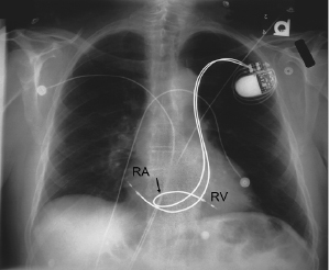
Although both single chamber ventricular and dual chamber systems have been placed through a persistent left SVC via the CS,16 it is preferable to approach implantation from the right side when this anomaly exists (Figure 5.3). Rarely, there is a co-existent absence of the right SVC with all brachiocephalic flow entering into the CS. Such a condition should be excluded before implantation is attempted from the right side in patients with a persistent left SVC. The increasing experience with pacing from the coronary venous system, coupled with the relative ease of entering these vessels in the case of persistent left SVC, suggests that this is a reasonable alternative in the latter patients. Other options for patients with anomalous venous drainage include an iliofemoral approach or an epicardial implantation, which now may be performed through a subxiphoid or thoracoscopic approach.
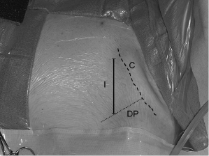
Venous Access
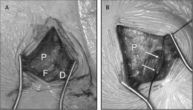
Figure 5.4 illustrates the two major easily identifiable landmarks (clavicle and deltopectoral groove) for implantation in a left infraclavicular site. Venous access into either the axillary/subclavian or cephalic vein is usually achieved through an incision that will also serve as the portal for subcutaneous generator placement. Local anesthetic is injected through a small-gauge needle along a line 4–6 cm long and two fingerbreadths below and parallel to the clavicle. If the cephalic vein is used, the incision begins about 0.5 cm lateral to the deltopectoral groove and is extended medially; otherwise, the incision may be placed just medial to the groove. This method provides adequate exposure for access to either the subclavian or cephalic vein.
Some operators begin with a smaller incision specifically located to achieve venous access, after which the incision is extended or a new one is made for the pocket. This is necessary when a supraclavicular approach to the subclavian vein or a jugular venous access is contemplated. In the latter situations, the leads are tunneled over the clavicle to the generator, which is placed in the usual ipsilateral infraclavicular position.
Pacing leads may be introduced through a venotomy in an exposed vein (cephalic, jugular, iliofemoral), or venous access may be achieved using the Seldinger technique. The latter approach provides easy access to a relatively large central vein, obviating the need for surgical dissection. In addition, the use of the dilator-sheath technique facilitates the introduction of multiple large leads and provides a means (via a retained guidewire) to re-enter the venous system should that be necessary. Nevertheless, the subclavian puncture poses the risk of injury to nearby structures, including the artery, lung, thoracic duct, and nerves, and it is sometimes the most hazardous part of the implantation procedure.
Axillary Vein Approach
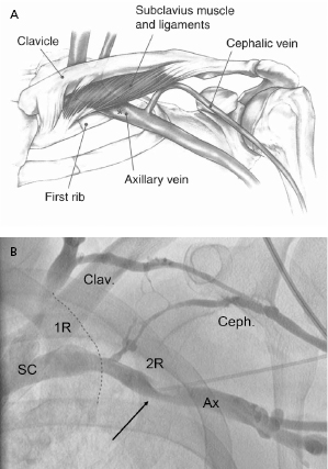
The Seldinger approach to the subclavian vein has long been a popular method of gaining rapid access to the central venous circulation. However, the traditional percutaneous subclavian approach may result in access to the medial aspect of the vein, which may later cause entrapment of the lead between the subclavius muscle and the costoclavicular ligament. Forces exerted on leads in this position may predispose them to insulation failure and/or conductor fracture (Figure 5.5). This may be most problematic for some polyurethane leads (especially those made with Pellethane 80A), which appear to be particularly susceptible to failure when placed via the subclavian route. These observations have led to the development of techniques to access the axillary vein by direct needle stick. This method appears to be safe and effective and it is more likely to be successful than cephalic vein cutdown.17
The introduction of the tear-away sheath has provided an effective means for the insertion of permanent pacemaker leads, and this method is now the most frequently used. The efficacy and safety of axillary and subclavian entry are increased by taking measures to distend the vein (proper hydration, leg elevation) and place it in the proper position (by placing a wedge under the patient’s shoulders and by adduction of the ipsilateral upper extremity).
We find ipsilateral upper extremity contrast venography to be helpful in demonstrating patency of the vessel, ruling out any anomaly which would preclude access, and providing a “road map” for using the axillary access technique. Adequate opacification of the axillary/subclavian vein is achieved by the injection of a bolus of 10–20 mL of iodinated contrast through a large-bore cannula in an ipsilateral arm vein. This should be followed immediately by injection of a saline “chaser” to hasten the transit of the contrast solution. The amount of fluid and rate of injection are gauged by fluoroscopic observation of the course of dye into the central veins. It is important that enough contrast be used and that adequate time be given for the contrast to fill the subclavian vein or collateral vessels. If the vessel is patent, there is often enough lingering contrast to allow an exploring needle to be directed at it.
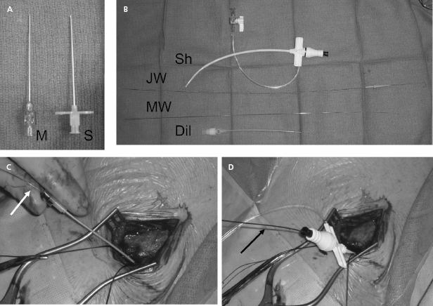
Our current practice is to use a smaller gauge micropuncture system for all percutaneous vascular access; this system is safer and usually less painful (Figure 5.6). The micropuncture needle, attached to a 10-mL syringe containing a few milliliters of local anesthetic or saline, is introduced through an incision that has been dissected to the underlying pre-pectoral fascia. The needle enters the pectoral muscle with the access needle just medial to the coracoid process on anteroposterior fluoroscopy. If a submuscular pocket is to be used, it is best to access the vein through the floor of the pocket with the needle. This will prevent excessive angulation of the leads between the access site and the pocket. Through the floor of the submuscular pocket, the axillary vein may be extremely shallow, and care is needed to avoid entry into the thorax. The needle is then directed under fluoroscopy to the point at which the lateral border of the first rib appears to cross the inferior margin of the clavicle (Figure 5.7). The needle approach is angulated to a degree such that the first rib is struck with the needle if the vein is not entered. By walking the needle up and down the first rib on repeated passes, the axillary vein is eventually entered. Small amounts of anesthetic may be injected along this course. Negative pressure is exerted on the syringe as the needle is advanced so that blood is aspirated on entry into the vein.
After advancement, the needle should not be redirected; doing so may lacerate underlying structures. If venous entry is not obtained, the needle should be withdrawn, cleared of any obstructing tissue, and re-inserted in a slightly different direction. Inadvertent arterial entry is apparent with the appearance of pulsatile bright red blood. Prompt withdrawal of the needle and compression at its entry site is usually all that is necessary to obtain hemostasis. Repeated unsuccessful attempts to enter the vein suggest a deviation in anatomy or occlusion of the vessel. In either situation, the risk of complication is increased with additional blind needle insertions. At this point one should consider a repeat contrast injection to determine vessel patency and to provide an updated road map.
On successful entry of the needle into a vessel, the character of the aspirated blood is examined. Dark non-pulsatile flow suggests a venous location; however, non-pulsatile flow does not exclude arterial entry, and pulsatile flow is sometimes noted from a vein (e.g. tricuspid regurgitation, right heart failure, cannon waves). Once vascular access is achieved, the syringe is detached (taking care to prevent air from entering the venous system) and a micropuncture wire is inserted through the needle and advanced under fluoroscopy to the inferior vena cava (IVC). If this is accomplished, inadvertent aortic entry is precluded; merely observing the guidewire coursing to the right of the sternum or even into a ventricular chamber does not exclude its presence in a tortuous ascending aorta or its passing retrograde into the left ventricle (LV). It is critically important that entry into the proper venous structure is confirmed prior to advancing a dilator or sheath over the wire.
If resistance to advancement of the guidewire is encountered, the guidewire should be withdrawn through the needle with great care to prevent shearing off the distal wire by the needle tip. If any difficulty is encountered with withdrawal, both the wire and needle should be withdrawn together or, if enough wire has been passed into the vein, the needle may be withdrawn and a small-lumen plastic catheter advanced over the wire and into the vein. In the latter situation, contrast may then be injected through the catheter to identify the problem and a more torqueable wire capable of being directed appropriately can be introduced.
After the micropuncture wire has been properly placed, a 4- or 5-Fr micro-puncture dilator is placed over the wire and the wire withdrawn, taking care to avoid entry of air into the vasculature. A standard J-wire or glidewire is then placed through the micropuncture dilator and passed into the IVC. The access procedure may be repeated for as many leads as will be implanted during the procedure. Some operators prefer to use a single access site and retain the guidewire throughout the case. Although this potentially reduces the risk of vascular injury or pneumothorax, this approach may create problems with lead–lead interaction during positioning within the heart.
Once the guidewire is positioned in the IVC, a commercially available peel-away sheath–dilator combination (7–9 Fr, depending on lead size) may be advanced over the wire into the SVC, which will provide access for the introduction of pacing leads. The relatively stiff, straight dilator should be molded into a gentle curve by the operator before insertion. Advancement of the device under the clavicle may be facilitated by torqueing it as if it were being screwed into place. Considerable resistance may be encountered if the subclavian vein has been entered medially through a fibrous or calcified ligament. Entrance into such a location may be a marker for future lead entrapment; thus, one may consider seeking a more lateral entry site. If the site is retained, the use of a stiffer guidewire may be advantageous in such a situation, as may the passage of initially small, then progressively larger dilators. Excessive force should not be necessary once the sheath has entered the vein. Fluoroscopic confirmation of proper alignment of dilator and wire is necessary if resistance is encountered. On occasion, countertraction on the wire while advancing the dilator is helpful. The sheath should not be allowed to slide over the tapered tip of the dilator, nor should the dilator be unprotected by a guidewire at any time during advancement.
Once it is properly positioned in the SVC, the dilator is removed while the guidewire is retained within the sheath to allow for the introduction of a second sheath if necessary. A clamp should be applied to the end of the guidewire to prevent its accidental migration into the vein. Care should be taken to limit the possibility of the aspiration of air through the large-bore open sheath by pinching its orifice until the lead is inserted. If possible, the patient should not be heavily sedated and should be instructed to avoid deep inspiration during this process. Deep breathing, and particularly snoring, greatly increases the chance of significant air embolus through an unvalved sheath. The use of tear-away sheaths with hemostatic valves is helpful in limiting bleeding and preventing air embolism, and should be used whenever possible.
The pacing lead is introduced carefully to avoid kinking the tip and advanced into the right atrium or IVC, at which time the sheath is withdrawn and peeled apart proximal to the venous entry site to prevent injury to the vessel. Some operators prefer to retain the sheath until the lead is placed in its final position in the heart. If a dual chamber device is to be employed, the retained wire or a second access wire is used to introduce a second sheath. If only one lead is to be used, it may be helpful to retain one guidewire so that venous re-entry is facilitated should the lead prove inadequate.
Cephalic Vein Approach
The cephalic vein resides in the sulcus between the deltoid and pectoral muscles. This area is readily identified by palpation and is occupied by loose connective tissue and fat, which are easily separated to reveal the underlying vein that sometimes lies fairly deep in this groove. The consistent course of this vessel, its reasonable size, and the direct path it takes to the central venous system make it useful for transvenous lead placement. On occasion, however, this vessel is small, consists of a plexus of tiny veins rather than a larger single channel, or takes a circuitous route to the subclavian vein. These conditions may make lead insertion difficult or impossible. In addition, the occasional difficulty in inserting two leads into the cephalic vein may limit the opportunity of using this approach for dual lead systems in some patients.
The vein is isolated along a 1–2-cm length within the groove and ligated distally with a silk suture (Figure 5.8). A ligature is looped but not tightened around the proximal aspect of the vein for hemostasis. The vein is entered by venotomy using a straight blade or with iris scissors. Using a vein pick, the tip of a 4- or 5-Fr dilator is placed in the venotomy and used to guide a floppy or hydrophilic-coated wire to secure access. Use of an angled glidewire with a torquing tool can be particularly helpful in negotiating the junction between the cephalic and axillary veins, which may form an acute angle in some patients, taking the wire peripherally down the arm rather than centrally to the thorax. A dilator–introducer sheath combination may then be used as described previously for the retained wire method in the subclavian approach.
The greatest benefit of the cephalic approach is its margin of safety compared with that of the axillary/subclavian puncture—there is almost no risk of pneumothorax or hemothorax. Although the cephalic vein itself is often sacrificed by this hybrid procedure, there is rarely any clinical consequence. In either case, the guidewire provides virtually unlimited access to the central venous system. Tearing of the vein may result in significant bleeding from tributaries into the pocket, which may be controlled with a purse string suture around the venous access site.
Rarely, the cephalic vein takes an aberrant course or a pectoral vein is inadvertently accessed. In such cases the guidewire may easily enter the subclavian vein, but it may not be possible to manipulate a sheath over the wire successfully, which necessitates abandoning the technique and sacrificing the vein. In other cases, the vein may spasm or invaginate by passage of the sheath essentially grasping it and preventing its advancement or removal. Application of a vasodilator (e.g. nitroglycerin) or actually cutting the constricting vein, exposed by pulling back on the dilator, may be necessary to insert the sheath fully. Despite these potential limitations of the cephalic technique, an experienced operator can successfully implant leads by this approach in most cases when it is attempted.
Subclavian Vein Approach
Despite widespread use in the past, the subclavian vein approach should be used rarely in favor of the axillary and cephalic access methods described above. On occasion, when these two methods are unsuccessful, the traditional subclavian vein approach may be required and so it will be described further.
Preparation of the patient is similar to the axillary vein approach described above. Contrast venography through the ipsilateral arm may be helpful to assure patency of the vein and to define its anatomical course, which may vary in different patients. Temporarily raising the patient’s legs on a wedge may help to distend the vein and make puncture easier. The patient’s arm should be pulled caudally to flatten the clavicle and minimize “hunching” of the shoulders.
The access needle, attached to a 10-mL syringe containing a few milliliters of local anesthetic or saline, is introduced through an incision that has been bluntly dissected to the underlying pre-pectoral fascia. The tip of the needle is advanced, bevel down, along this tissue plane at the level of the junction of the medial and middle thirds of the clavicle, and directed toward a point just above the sternal notch. The appropriate point to meet the clavicle is at the angle evident on palpation or fluoroscopy. On reaching the clavicle, the needle’s angle of entry with respect to the thorax is increased until the tip slips under the bone. Alternatively, the needle is marched anterior to posterior along the clavicle using the thumb of the non-dominant hand to depress the needle or barrel of the syringe. Once under the clavicle, the needle and syringe should be maintained parallel to the floor; this prevents the needle from plunging ever more posteriorly as the needle is advanced. Negative pressure is exerted on the syringe as the needle is advanced so that blood is aspirated upon entry into the vein. Once under the clavicle, the needle should not be redirected; doing so may lacerate underlying structures. If venous entry is not obtained, the needle should be withdrawn, cleared with saline, and re-inserted in a slightly different direction. The subclavian artery is cranial and posterior to the subclavian vein. Entry into the subclavian artery should lead to appropriate adjustments in the needle’s trajectory. In addition, crossing under the clavicle from too lateral a position will often result in arterial access.
Once venous entry is assured, a J-wire or glidewire is passed and the procedure continued as described in ”Axillary vein access.”
Pacemaker Pocket
The pacemaker is usually placed in a subcutaneous position near the site of venous entry. Generators have continued to decrease in size and can be placed easily in most patients, including those having a paucity of subcutaneous tissue. Most often, the device is placed in the infraclavicular area through the incision used to obtain venous access. Local anesthesia is applied to the subcutaneous tissue, which is then dissected down to the pre-pectoral fascia. The pocket should be created in the plane just above this fascial layer and below the subcutaneous fat. Placing the pocket too superficially in a subcuticular pocket may lead to erosion or to a pain syndrome requiring re-operation.
A pocket directed inferomedially over the pectoral fascia and large enough to accommodate both the generator and redundant lead is made in this tissue plane by a combination of electrocautery and blunt dissection. Too small a pocket may result in tension exerted on the overlying tissue by the implanted hardware; too large a pocket invites future migration or “flipping over” of the generator. Augmentation of anesthesia with a rapidly acting parenteral agent is recommended during the brief time it takes for pocket creation, because this is usually the most painful part of the procedure. Attention to hemostasis is necessary, but significant bleeding rarely accompanies blunt dissection and electrocautery in the proper tissue plane. Stripping away the pectoral fascia during the dissection often leads to excessive bleeding from the denuded muscle, especially in patients taking antiplatelet agents. On completion of its formation, the pocket may be flushed with antibacterial solution and temporarily packed with radio-opaque sponges. All sponges used in this fashion should be accounted for in order to avoid leaving one in the pocket. Even a radio-opaque sponge may be missed by fluoroscopy if it is under the generator and only casual observation is made. The use of oversized laparotomy sponges that cannot be concealed in the pocket may also avoid this problem.
In some circumstances (e.g. sparse subcutaneous tissue, large generator, impending erosion from a previous device, concerns about cosmetic appearance) the generator may be placed subpectorally or under the breast.18 These procedures should be planned ahead of time with the assistance of appropriate personnel (e.g. a plastic surgeon) as needed. The subpectoral site is best accessed by dissecting the natural plane between the pectoralis major and minor muscles. This plane is identified by blunt dissection in the deltopectoral groove and carried inferiorly and medially. Alternatively, a muscle-splitting incision can be made in the body of the pectoralis major itself. When used, the subpectoral location should be noted in the operative report for reference for future revisions or generator changes.
A pocket located at a distance from the site of lead insertion requires that the leads (with or without extenders) be tunneled through subcutaneous tissue to its location.
Lead Implantation
A variety of leads are available for endocardial placement. They differ in composition, shape, electrode configuration, and method of fixation. Passive fixation leads have tines that anchor them in the trabeculated RV or atrial appendage. Active fixation leads employ a helix as the mechanism for fixing them to the endocardium. The helix may be extendable and retractable, or may be permanently fixed at the tip. In some lead models, the fixed helix is covered with an absorbable agent to facilitate passage of the lead to its site of implantation, by which time absorption of the material exposes the helix and allows it to be fixed to the heart. In general, leads with extendable–retractable helices are easier to implant and easier to remove if necessary.
Both active and passive fixation leads have advantages and disadvantages (Table 5.2) and may be used for either atrial or ventricular placement. Steroid-eluting passive fixation leads may offer some benefit in terms of lowered subacute and possibly chronic thresholds. Despite the progress in lead designs and their overall excellent performance, the failure over time of several models of these devices remains a cause for concern.19,20
| Active fixation lead | Easy passage |
| Low acute dislodgement rate | |
| Unrestricted positioning | |
| Easier removal of chronic implant | |
| Higher capture thresholds | |
| Passive fixation lead | Greater electrode variety |
| Lower thresholds | |
| More difficult passage | |
| More difficult chronic removal | |
| Higher early dislodgement rate |
Table 5.2 Lead characteristics
Before their introduction, leads should be inspected for anomalies. Proper sheath selection should be made to allow passage of the lead and, if used, the retained guidewire. Active fixation leads should be tested on a clean surface to ensure that the helix extends and retracts appropriately. The connector pin of the lead should be appropriate for the selected pulse generator. For the past 20 years, the IS-1 pin connector system has been used almost exclusively for new atrial and RV pacing leads. The suture sleeve should be positioned at the proximal portion of the lead and prevented from migrating distally during lead placement.
Stylets of varying length and stiffness are used to manipulate and steer the lead in the body. Stylets should be kept clean and dry to facilitate insertion and withdrawal from the lead. Torque applied to a shaped stylet will help rotate the lead to its desired location. Steerable stylets are now available that allow for in-situ alteration of the degree of curve they provide to the lead tip, which may facilitate atrial placement or selective-site ventricular lead placement. One lead model has no central lumen for a stylet and uses a steerable sheath system for implantation.
Leads are usually inserted through a valved peel-away sheath. Care should be taken to avoid damaging the lead tip when pushing it through the valve. The central venous system is usually traversed easily and the lead advanced to the low right atrium or IVC. On occasion there may be difficulty in advancing the lead through a kink in the sheath or through tortuous central vasculature. Withdrawing the sheath slightly, advancing the retained guidewire along with the lead, and sometimes withdrawing the stylet to soften the lead tip may prove helpful in these situations. When tortuous or stenosed central vasculature is encountered, a long sheath may be required for passage of the lead into the heart.
Although the retained-guidewire approach facilitates the insertion of the two leads required for dual chamber pacing, manipulation of one lead may affect the position of the other, especially when silicone-coated leads are used. Some implanters consider that two independent sheaths should be used and not withdrawn until both leads have been positioned, or that separate venous sites (e.g. cephalic and axillary or two separate axillary entry sites) be accessed for each lead. If necessary, however, two leads may usually be inserted and positioned through the same access site by using the retained-guidewire technique. Good fluoroscopic imaging is a key to successful lead implantation, and care should be taken always to image the tip of any lead as it is advanced, and with any lead manipulation in the heart.
Ventricular Lead Positioning
In dual chamber systems, the RV lead is usually positioned first because it may supply back-up pacing, its position is usually more stable than that of the atrial lead, and it is usually the most important of the leads. LV lead placement is described in Chapter 9.
Once the RV lead has been advanced to the low right atrium or IVC, the straight stylet is withdrawn a few inches to allow the lead tip to catch in the right atrium; further advancement of the lead will cause its distal portion to form a J shape, which may then be rotated toward the tricuspid valve (Figure 5.9A–F). Slight retraction results in prolapse into the RV, at which time the lead can be either advanced into the pulmonary artery or directed down toward the apex by advancing the stylet while the lead is slowly pulled back. Prolapsing the lead into the RV ensures that the lead is not in the CS and is not passing through the tricuspid valve apparatus. Entry into the pulmonary artery confirms that the lead has traversed the RV and is neither in the atrium nor in the CS. The lead may then be pulled back as the stylet is advanced. Tined leads may become readily entangled with the tricuspid apparatus when prolapsed across the valve. Directly steering these leads through the valve may be necessary.
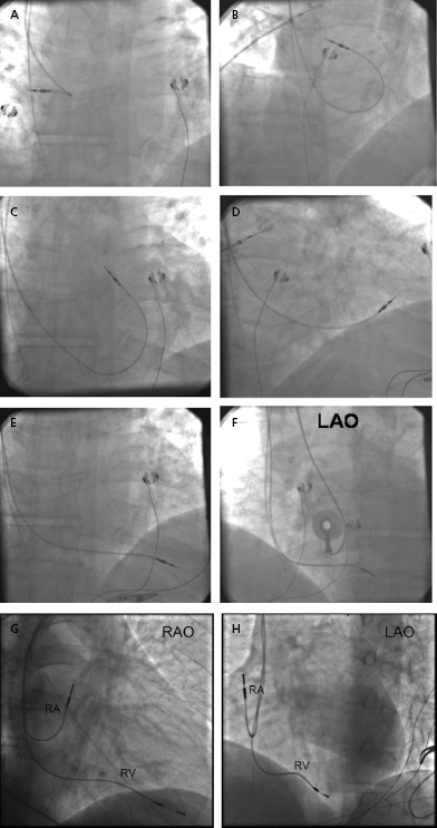
Once the lead tip falls toward the apex, the patient is asked to inspire deeply and the lead is advanced into place. This maneuver is often accompanied by ventricular ectopy, the absence of which suggests that the lead is not in the ventricle. An alternative method of gaining entry to the RV is to form the stylet into a dog leg or a J shape and to use it to direct the lead across the tricuspid valve or to facilitate prolapsing the lead from the right atrium. Once it is in the RV, the shaped stylet may be replaced with a straight one to facilitate positioning at the apex. The proper fluoroscopic appearance of the RV apical lead is one in which the lead’s tip is to the left of the spine and is pointing anteriorly and slightly caudal (Figure 5.9G,H). Visualization of the lead in multiple planes should be performed to confirm appropriate location of the lead.
For the patient with LBBB or AV block with a ventricular escape mechanism, special care needs to be taken when crossing the tricuspid valve to avoid bumping the right bundle branch if no temporary pacing wire is in place. The transient block in conduction may result in prolonged asystole and even death if temporary pacing cannot be quickly established. In these situations, less experienced operators may wish to place a temporary pacing wire at the outset of the procedure to avoid this complication.
In the anteroposterior projection it may not be possible to distinguish whether a lead is in a posterior coronary vein, the LV, or the RV apex. Left oblique views and the 12-lead ECG pattern of ventricular activation (QRS morphology) during pacing are helpful in avoiding such lead misplacement. If a lead is inadvertently placed in the LV, the paced QRS complex will usually show a right bundle branch block (RBBB) pattern, whereas positioning in the RV will usually show a LBBB pattern. In patients with LV prominence and/or counterclockwise rotation of the heart, the lead tip may not appear to extend far enough to the left border of the cardiac silhouette. Imaging in the right anterior oblique (RAO) position may be helpful in such circumstances; observing the position of the lead with respect to the tricuspid valve allows an estimation of how far the lead projects into the RV. Pacing at 10-V output is performed to exclude diaphragmatic stimulation by the lead, which may indicate microperforation and should usually lead to repositioning of the lead.
Once the proper position has been confirmed, the active fixation mechanism, if present, should be deployed while viewed under magnified fluoroscopy. The stylet is then partly withdrawn and pacing parameters (R wave size, pacing impedance, and capture threshold) are determined. High-output pacing is performed again. Once in place after stylet withdrawal and lead fixation, the tip should maintain a relatively stable position and not appear to bounce with cardiac contraction. A slight loop of lead (or “heel”) should be retained in the right atrium to avoid tension at the tip during deep inspiration. Too large a loop may result in ectopy, lead dislodgement, or prolapse into the IVC, while too little slack in the lead creates a risk for dislodgement from mediastinal shift when the patient resumes upright posture and normal inspiration.
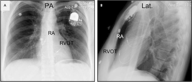
Although an apical RV lead position is usually preferred for reasons of stability, there are occasions when another location in the RV is required (e.g. a retained ventricular lead, which might result in contact potentials). Efforts to obtain a more physiological activation sequence and a more efficient mechanical contraction from RV stimulation have led some investigators to advocate positioning the lead in the RV outflow tract (Figure 5.10) or on the interventricular septum (Figure 5.11).21 In these circumstances, the use of an active fixation lead is required. To place a lead in the outflow tract or septum, the lead is prolapsed into the pulmonary artery as described. By withdrawing the lead with a curved stylet and torque to drive the tip into the septum, the septum can be mapped and the lead fixed. The hemodynamic benefits of routinely seeking such a position compared with the stability of the traditional apical location are unproven,22 but this position may reduce the risk of free wall perforation and diaphragmatic stimulation when an active fixation lead is required.
Stay updated, free articles. Join our Telegram channel

Full access? Get Clinical Tree


