Follow-Up of the Patient with a CIED
1 University of Alabama at Birmingham, Birmingham, AL, USA
2 Yale University School of Medicine, Yale-New Haven Hospital, New Haven, CT, USA
Introduction
Cardiovascular implantable electronic devices (CIEDs) include cardiac pacemakers, implantable cardioverter–defibrillators (ICDs), implantable cardiovascular monitors, and implantable loop recorders (ILRs). This chapter outlines the general principles of the follow-up of CIEDs, with a specific focus on pacemakers and ICDs. Various sources of electromagnetic interference (EMI) encountered by the CIED patient in the medical and non-medical environments are briefly reviewed, along with suggestions to mitigate the adverse effects from these interactions. The management of CIEDs in other special situations, such as in the perioperative period, and in patients nearing end of life or requesting withdrawal of therapy, is also summarized. Finally, there is a brief discussion on device advisories and their management.
Goals of CIED Follow-Up Assessment
The follow-up evaluation of a patient with a CIED begins in the immediate post-implantation period and extends throughout the patient’s life, rather than throughout the life of the device system per se. The original indications for device insertion require periodic review, and new indications for modification of the existing system also warrant continuing evaluation. The device physician needs to assess those symptoms not satisfactorily treated by the device as well as those symptoms potentially caused by the device. Systematic record keeping is an important part of this process, particularly in following end-of-life parameters and in tracking patients whose systems may be subject to product recall or failure.
It remains a challenge to optimize the functioning and longevity of a device system in the face of constantly changing patient needs, whether those changes are in lifestyle, medical circumstances, cardiac function, or electrophysiological milieu. The issue of who should perform device follow-up evaluations remains an ongoing debate—what is clear is that the relevant skills must be continuously and finely maintained.1 This chapter explores these issues and examines the methodology of device follow-up evaluation.2,3
Immediate Post-Implantation Period
Following implantation of a new pacemaker or ICD system, the patient is generally observed on a cardiac monitor for 24 h. Generator replacements are performed on an ambulatory basis. The Heart Rhythm Society (HRS) is developing guidelines for clinical scenarios in which less than 24-h monitoring for primary implants may be considered without inpatient admission (i.e. observational status).
Prophylaxis with a parenterally administered antibiotic that has in-vitro activity against staphylococci is recommended before the procedure (IV cefazolin within 1 h or IV vancomycin within 2 h, before skin incision).4 A portable chest radiograph may be obtained immediately following implantation to exclude a pneumothorax. Posteroanterior (PA) and lateral chest radiographs are obtained within 24 h to confirm satisfactory positioning of the pacing and/or ICD lead(s) and to serve as a baseline for subsequent comparisons. A twelve-lead electrocardiogram (ECG), ideally with pacing, is obtained before discharge.
Most essential in the immediate post-implantation period is education of the patient. The importance of always carrying a device identification card must be stressed. Medical alert bracelets are often recommended as well. The patient is asked to refrain from vigorous activity involving the ipsilateral arm for a period of approximately 4 weeks to minimize the possibility of lead dislodgement and minimize undue stress on the incision. The patient should also keep the incision completely dry for 5–7 days to minimize the chance of infection. Precautions to minimize interference from various household, industrial, and medical sources of electromagnetic energy should be discussed; equally important, the patient should be reassured regarding use of common household appliances such as microwave ovens. Temporary driving restrictions (usually for 6 months) may be appropriate for patients presenting with syncope or those undergoing ICD implantation for secondary prophylaxis until the follow-up assessment confirms that the device is functioning normally; otherwise driving may be resumed in 1–2 weeks. Plans are made for outpatient wound evaluation and suture or staple removal if needed, generally to occur within 2–4 weeks. Patients are asked to be attentive to any signs of fever or infection, such as pain, redness, swelling, or drainage at the incision site.
The Follow-Up Clinic and Record Keeping
The personnel necessary for the device follow-up assessment include a supervising physician, a device nurse or technician, and clerical staff for record keeping and outpatient scheduling. Personnel directly involved in device follow-up evaluation must be thoroughly familiar with all aspects of device function. The site of the device follow-up evaluation should allow history taking and patient examination, and should be fully equipped to allow for analysis of device function (Table 11.1). This includes capabilities for 12-lead ECG (with and without a magnet), radiography (and fluoroscopy, if possible), trans-telephonic and ambulatory ECG monitoring, and availability of the programmer’s and physician’s manual for every model of device encountered. The telephone numbers for technical support of all device manufacturers should be available. Depending on the number of different device models employed by the clinic, extensive familiarity with a wide variety of programming devices may be necessary because of the lack of universal programming.5 A resuscitation cart, defibrillator, and transcutaneous pacemaker should be immediately available. The clinic staff should be capable of performing advanced cardiac life support.
| Clinic personnel | Device physician |
| Device nurse or technician | |
| Clerical staff | |
| Device and patient data | Patient’s name, age, identification, address, phone number |
| Pulse generator data: model, serial number | |
| Lead(s): model, serial number | |
| Operative note from implant with implant data | |
| Complete follow-up records | |
| Telephone numbers for device technical support | |
| Equipment | Examination room |
| Pacemaker or ICD programmers | |
| Magnet | |
| Physician manuals for each model device followed | |
| ECG machine | |
| External defibrillator and transcutaneous pacemaker | |
| Code cart | |
| Ancillary requirements | X-ray and fluoroscopy |
| Tilt table | |
| Blood chemistry laboratory | |
| Holter/event monitoring |
Table 11.1 Essential components of a device clinic
Record keeping is an indispensable component of a device clinic. Its purpose is to record accurately such patient demographics as name and address, to identify specifics of the device system used (model and serial numbers, implant values), to track patient symptoms and various parameters of pacemaker or ICD function (e.g. sensing and pacing thresholds, identified changes in magnet rate), and to update any changes in programmed parameters. Such records may be computer stored and allow for the generation of comprehensive updated reports. Record keeping also allows for organization and maintenance of strict schedules for patient follow-up assessments. This promotes identification of potential problems with device function well before they are actualized, rather than having patients drop in only after the problem has manifested.
The establishment of a federal pacemaker registry was mandated by Medicare guidelines, wherein specifics of pacemaker data, such as patient demographics and model and serial numbers, are reported at the time of implantation. The National Cardiovascular Data Registry (NCDR) has been mandated by the Centers for Medicare and Medicaid Services (CMS) to collect data on all ICD generators and lead implants. Such registries, coupled with manufacturer-generated patient lists and accurate record keeping by the device physician, should facilitate contacting patients if a systematic problem with a particular type of device system is identified or if a product advisory/recall is issued. If the physician has observed a problem, such as premature battery depletion, the manufacturer can then be consulted to determine whether others may have made similar observations.
Independent of a formal recall, it is the responsibility of the device physician to decide whether corrective measures are warranted in a particular case. If a recall or advisory on a particular device product has been issued, the nature of the potential malfunction should determine the timing of the device system revision, if required at all. If the reported component failure is random and unpredictable, then replacement should be undertaken more rapidly, especially in those patients who are deemed “pacemaker dependent” [see “Pacemaker dependence” and “Device advisories (alerts and recalls)”]. Unfortunately, as of this writing, there is no manufacturer-independent, large-scale national device/lead database that allows physicians and their patients to be notified in a timely fashion of pacemaker system malfunctions.6 Thus, the device physician must be ever vigilant as to trends of potential device malfunction in their practice as well as to reports from others, whether via other physician’s or manufacturers’ notifications.
The Outpatient Visit
Even a routine pacemaker or ICD follow-up visit is a labor-intensive encounter with much to be accomplished in a timely manner, including a brief history, examination, device evaluation, troubleshooting, reprogramming, and record keeping. By keeping the goals of the visit in focus and maintaining an orderly approach to follow-up, the process can be made efficient (Table 11.2).
| History Physical examination Chest X-ray and fluoroscopy Electrocardiography Magnet application Device interrogation Communication with other physicians as needed (e.g. heart failure specialist, radiation therapist, surgeon for preoperative assessment) |
Table 11.2 Elements of the outpatient visit
The first visit, approximately 2–4 weeks subsequent to implantation, is primarily directed toward evaluation of the healing wound. This is particularly important in patients with diabetes, chronic renal insufficiency, impaired cardiac perfusion due to depressed ejection fraction, or smokers, all of whom are prone to slower healing, as well as in patients requiring anticoagulation (warfarin, dabigatran, rivaroxaban, etc.) or antiplatelet agents (aspirin, clopidogrel, prasugrel, etc.), in whom pocket hematomas can prove catastrophic. Symptoms are reviewed as at any visit. Chest radiographs (PA and lateral) and ECGs with and without pacing can be repeated at this time. Most problems arising within 2 weeks of implantation relate to either lead dislodgement, exit block, or healing of the incision or pocket. Arrangements for trans-telephonic or other type of remote monitoring are made, as well as for the 3-month check-up. At that point, the inflammation associated with the tissue–electrode interface has generally resolved, allowing for assessment of chronic pacing and sensing thresholds. Subsequent visits should focus on device maintenance, optimization of function, and evaluation of patient complaints. After the 3-month check-up, patients are generally seen once or twice yearly, or as otherwise dictated by their clinical needs. With increasing reliability and automaticity built into modern pacemakers, and with the availability of reliable remote monitoring systems, less frequent in-office checks have become more feasible. Guidelines for the frequency of in-person and remote follow-up of CIEDs are discussed later.
History
The elicitation and evaluation of symptomatology require careful sleuthing on the part of the device physician. Perceptions of pain, well-being, or vigor may vary widely from patient to patient, depending on an individual’s “threshold” for discomfort or malaise. These may also be a function of a patient’s fears and expectations. If the patient does not feel “100% better” after pacemaker insertion, does this reflect malfunction, or were the patient’s original symptoms multifactorial in etiology and not preventable by pacing alone? As such, it is sometimes difficult to distinguish symptoms that warrant only reassurance from those that may be subtle clues to underlying pacemaker malfunction, malprogramming, or “patient–pacemaker mismatch.” The latter is a term applied to the situation when the pacing system may be functioning perfectly appropriately, but fails to result in optimal patient functioning and indeed may even produce symptoms. For example, in an older patient who develops angina, it may be important to make the system less sensitive to activity, lower the upper rate limit, and have a relatively quicker decline of pacing rate once activity ceases.
Patients may have systemic or local symptoms (Table 11.3). Systemic symptoms include dyspnea, edema, chest pain, palpitations, dizziness, or syncope. These symptoms may be present at baseline, be exertional or postural, or be random and episodic.
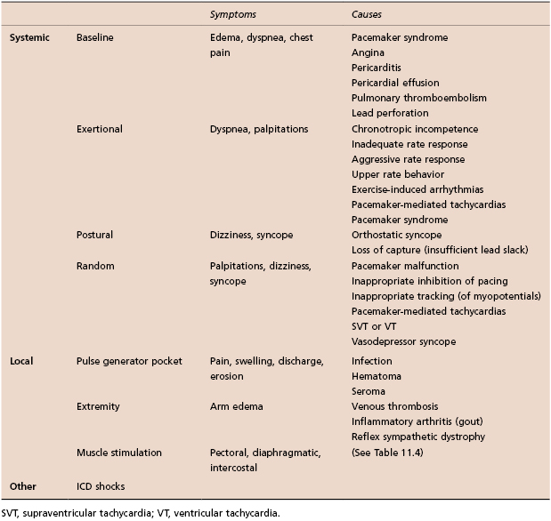
Table 11.3 Common symptoms in patients with CIEDs
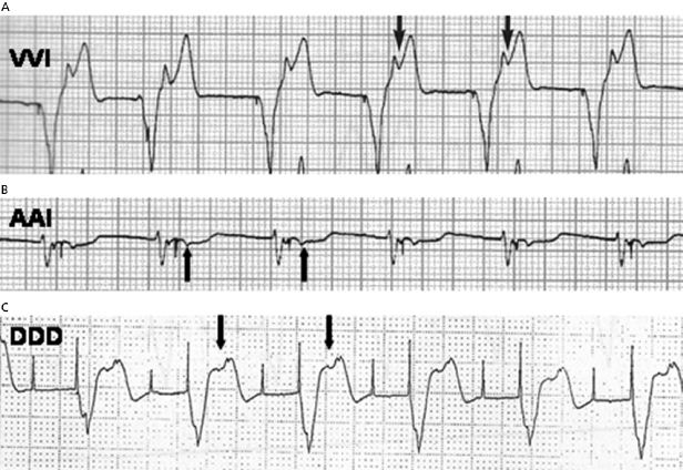
Pacemaker syndrome is an important cause of baseline symptoms.7,8 This phenomenon, commonly observed during single chamber ventricular pacing, results in hemodynamic compromise from retrograde activation of the atria in some cases and from cyclic losses of synchrony between the atria and ventricles in other cases (Figure 11.1). Patients may present with pre-syncope, syncope, malaise, fatigue, palpitations, or dyspnea. Loss of atrioventricular (AV) synchrony during pacing may produce systemic hypotension, AV valvular regurgitation, reduction in cardiac output, pulmonary congestion, and unpleasant neck pulsations (cannon A waves due to atrial contraction against a closed AV valve). In the worst-case scenario of AV dyssynchrony, retrograde 1:1 ventriculoatrial (VA) conduction may occur with ventricular pacing. Retrograde VA conduction is observed in approximately 80% of patients with sick sinus syndrome and even in a small minority of patients (15%) with antegrade high-grade AV block. The presence of retrograde VA conduction should be ascertained with electrocardiography, particularly in the inferior leads (e.g. II, III, and aVF), and/or telemetered intracardiac electrograms (EGMs). Blood pressure determinations should be made in the supine and erect positions with both ventricular pacing and during a non-paced rhythm if possible. Rarely, cardiac output determinations may also be required to demonstrate hemodynamic compromise associated with ventricular pacing. If pacemaker syndrome is identified, consideration should be given to reprogramming the pacemaker to reduce pacing dependence (e.g. decrease the lower rate), but ultimately revision to a dual chamber system may be required. Pacemaker syndrome should be considered not only with VVI pacing but also in any situation when AV synchrony is deranged; it can occur with AAI pacing secondary to long PR intervals and with DDD pacing in the setting of loss of atrial capture, inappropriate mode switching, pacemaker-mediated tachycardia (PMT), etc. The widespread and often insidious expression of pacemaker syndrome has led to a reappraisal of the choice of dual versus single chamber pacemaker implantation, as recently codified in an official HRS consensus statement.9
Baseline symptoms may occur from other causes. Some patients develop angina at baseline following device implantation, and might require the lower rate to be decreased. Sharp, pleuritic chest pain can result from pericarditis. Dyspnea can result from pericardial effusion or from pulmonary thromboembolism (PTE).
Exertional dyspnea or fatigue can occur due to lack of rate-adaptive pacing or inadequate rate response in a patient with chronotropic incompetence. On the other hand, an older patient might experience exertional angina due to an over-aggressive rate response. Upper rate behavior can account for exertional symptoms; e.g. a previously vigorous patient who receives a dual chamber system for complete heart block may be exertionally limited with an upper tracking rate of only 120 bpm, especially if electrical Wenckebach or 2:1 heart block develops at the pacemaker’s upper rate limit (Figure 11.2). Symptoms may result from exercise-induced arrhythmias potentially contributing to PMTs.

Treadmill testing may be useful in assessing exercise tolerance, chronotropic competence, and maximal heart rates achievable, either independent of pacing or in the setting of specifically programmed parameters. In rate-adaptive systems it is particularly useful to assess activity-sensing thresholds as well as the rapidity of pacing rate increases and decreases with activity. Upper rate behavior in dual chamber systems may also be appreciated with exercise testing (e.g. Wenckebach vs. 2:1 block); exercise-induced arrhythmias potentially contributing to pacer-mediated tachycardias may rarely be observed.
Postural symptoms can be due to orthostatic syncope, but intermittent loss of capture due to inadequate lead slack should also be considered.
Intermittent but random symptoms can be due to pacing system malfunction, inappropriate inhibition of pacing (due to oversensing of myopotentials, EMI, noise, or cross-talk) or tracking of myopotentials. This requires careful evaluation, including, determination of sensing and pacing thresholds, review of stored EGMs for oversensing, and performing special maneuvers to evaluate for myopotential inhibition or tracking. PMTs may also arise and generate symptoms. Reprogramming options to address this are discussed later. Problems unrelated to the pacing system such as spontaneous atrial or ventricular arrhythmias, and vasodepressor syncope should also be considered. Most devices have sophisticated diagnostics, often storing the actual EGM from any such tachycardia. This greatly simplifies evaluation. Many pacemakers allow the clinician to attempt to terminate supraventricular tachycardias (SVTs) with rapid pacing if the patient is in persistent tachycardia at the time of a follow-up visit. Additionally, certain pacemakers even allow for the programming of atrial antitachycardia pacing (ATP) to be automatically delivered for SVTs. Tilt testing may prove useful in revealing the presence of vasodepressor syncope. Under such circumstances, medical therapy with volume expansion, β-blockers, selective serotonin reuptake inhibitors, mineralocorticoids, or vasoconstrictors, such as midodrine, may prove useful. Pacemaker reprogramming may also be beneficial. Increasing the lower pacing rate or activating certain specialized “rate-drop” algorithms may provide assistance. There is evidence that certain rate-adaptive sensors responsive to cardiac contractility may be particularly efficacious in minimizing recurrent vasovagal spells.10 The extent to which any pacing system can improve on vasovagal syncope remains a source of controversy.11
Patients may complain of local pain, swelling, discharge, or erosion at the pulse generator site or of edema of the ipsilateral limb. In addition, stimulation of the diaphragmatic, pectoral, or intercostal muscles may be reported.
All patients with ICDs should be questioned about ICD shocks. Shocks can be appropriate (due to ventricular arrhythmias) or inappropriate (due to rapidly conducted SVT or oversensing). Symptoms preceding a shock can be very useful in discerning the etiology. Patients may perceive shocks that never occurred (phantom shocks). Troubleshooting of ICDs is discussed in Chapter 10.
Physical Examination
The physical examination is a critical aspect of device follow-up evaluations. Most attention will be directed toward the healing incision and device pocket, looking for erythema, tenderness, incipient or overt erosion, or pocket swelling.
Pulse Generator Pocket
Swelling over the pulse generator may represent hematoma formation, seroma, or pocket infection. Pocket hematomas occur in approximately 20% of patients who receive subcutaneous or intravenous heparin shortly post procedure.12 While a hematoma does not imply an infection, the risk of subsequent infection is heightened, and most would advocate prolonging the period of prophylactic antibiotics until the hematoma has resolved. Conservative management is all that is usually required, with temporary cessation of anticoagulants and more frequent follow-up to look for signs of pressure necrosis. Percutaneous aspiration of the pocket may actually be counter-productive, diminishing the tamponading effect and increasing the chances of further bleeding and infection.
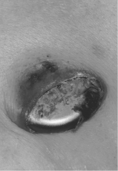
Patients may note caudal migration of the generator or superficiality of the pacemaker leads, but these phenomena are infrequent and of concern only rarely. In a healthy pocket, the generator is freely mobile beneath the skin. An immobile generator, especially when firmly adherent to the overlying skin, raises the possibility of occult infection or pre-erosion. Erosion of a generator or a lead is potentially quite serious and may result in systemic infection (Figure 11.3). A variety of approaches to “salvaging” an eroded system have been advocated, although ideally the entire system (including leads) should be explanted and replaced with a new system after an appropriate period of intravenous antibiotics. A fluctuant pocket should not be aspirated, as this may introduce infection into a sterile process and will not treat an infection if present. Suspected pocket infections should be surgically opened to confirm the diagnosis and to remove all hardware if the pocket is infected. Pacemaker infections are not adequately treated by prolonged courses of antibiotics alone.
Muscle Stimulation
Unanticipated stimulation of the pectoral, diaphragmatic, and rarely, intercostal muscles can occur from CIEDs (Table 11.4). Myopectoral stimulation may be appreciated at the pocket site and is almost exclusively seen in unipolar systems. Certain generators are manufactured with one insulated side intended to be placed against the pectoral muscle. Myopectoral stimulation may be attributed to placement of such a generator can with the uninsulated side down against the pectoral muscle (or the patient may have reversed the can by “twiddling”), leading to anodal stimulation of the underlying muscles; it may thus be corrected by inversion of the generator. Frequently, no problem is identifiable, but the situation may be corrected by reprogramming to a lower output to avoid invasive revision to a bipolar system. Reduction of voltage is often effective in eliminating muscle stimulation—far more so than reduction of pulse width duration. Pectoral muscle stimulation may also indicate lead insulation failure close to the muscle layer. Rarely, a dislodged lead that has retracted all the way to the pocket is the cause. The last two causes can result in myopectoral stimulation in unipolar or bipolar systems.
| Causes | |
|---|---|
| Pectoral (pocket) |
|
| Diaphragmatic |
|
| Intercostal |
|
Table 11.4 Inadvertent muscle stimulation with CIEDs
Diaphragmatic stimulation, if present, is usually apparent on physical examination, but rarely requires fluoroscopy for confirmation. It can occur as a result of right or left phrenic nerve stimulation, or by direct stimulation of the diaphragm. This problem is becoming more frequent with the use of biventricular pacing systems, where the lead placed in the coronary venous tributary is often in close proximity to the left phrenic nerve. Most current devices allow the left ventricular stimulation vector to be re-programmed; in most cases an alternate pacing vector decreases or eliminates phrenic stimulation. Direct stimulation of the diaphragm may occur through a thin ventricular wall, or, less commonly, through a perforated ventricle. In the former case, reduction of output may alleviate the problem. Another cause for diaphragmatic stimulation is (right) phrenic nerve stimulation with a misplaced or dislodged atrial or ventricular lead. Depending on which lead is responsible, the corrective approach may entail inactivation of the atrial channel, reduction of atrial output, or repositioning of the displaced lead.
General Aspects
Other important aspects of the physical examination include vital signs, with particular emphasis on pulse and blood pressure. The latter may vary significantly as a function of pacing mode (e.g. VVI vs. DDD) or pacing rate. Neck veins should be evaluated for the presence of cannon A waves. Cardiac examination should confirm paradoxical splitting of the second heart sound in most cases of right ventricular (RV) pacing, and should exclude the presence of a pericardial friction rub suggestive of cardiac perforation. The arm ipsilateral to the lead insertion site should be examined for edema, perhaps reflecting venous thrombosis, which is usually a spontaneously resolving phenomenon and rarely responsible for thromboembolism. Arm elevation is often helpful while endogenous thrombolysis and recruitment of collateral circulation take place. If symptoms are more marked, short-term anticoagulation with warfarin may speed the process. Edema coupled with inflammation may, less commonly, represent a gouty attack precipitated by the recent surgical implantation of a device system.
Dynamic Maneuvers
Carotid sinus massage may be employed to induce slowing to the lower rate limit, thereby confirming the ability of the pacemaker to capture. Rarely, carotid massage-induced slowing of the sinus node may be useful in dual chamber systems to differentiate SVT from physiological sinus tachycardia with ventricular tracking near the upper rate limit. In rate-adaptive systems dependent on sensing vibration, the generator may be tapped to demonstrate increases in the pacing rate. Physical manipulation of the pacing system should be undertaken to evaluate the integrity of the leads and their connections to the generator can. Traction applied to the generator or abduction of the arm ipsilateral to the generator may expose a previously unsuspected malconnection or lead fracture and result in loss of capture or myopectoral stimulation. Confirmation of continued capture should be made with the patient in the erect as well as supine position in cases where inadequate or insufficient lead “slack” may be present.
Myopotential sensing can result in pacing inhibition in single or dual chamber systems, triggering of ventricular pacing in dual chamber systems, or inappropriate shocks in patients with ICDs. Pectoral myopotentials may be elicited by isometric exercise involving the arm ipsilateral to the generator, whereas diaphragmatic myopotentials are elicited by deep respiration, coughing, or performing the Valsalva maneuver. The ability to observe real-time intracardiac signals as well as the universal adaptation of marker channels has greatly eased this evaluation. This is ordinarily an issue only for unipolar systems. If myopotential inhibition is elicited and clinically significant, reprogramming to a reduced sensitivity, to an asynchronous pacing mode, or to a triggered pacing mode may be undertaken to ensure continuous pacing in the pacemaker-dependent patient. Consideration of changing the unipolar system to a bipolar system is another option. However, myopotential sensing can occur in bipolar systems due to lead insulation breach, or in ICDs with an integrated bipolar lead, due to reversal of coil connections or a loose set-screw to the distal coil. Selected intermittent problems that may be revealed by special maneuvers are listed in Table 11.5.
| Problem | Major consequence(s) | Dynamic maneuver during physical exam |
|---|---|---|
| Myopotential sensing | Oversensing | Diaphragmatic: Cough Valsalva maneuver Deep respiration |
| Pectoral: Ipsilateral arm (isometric) exercise | ||
| Lead or connector problems | Oversensing Loss of capture | Traction on pulse generator Ipsilateral arm movements (abduction) |
| Problems at electrode-tissue interface: Insufficient slack Excessive motion | Loss of capture | Positional changes (supine, erect) |
| Diaphragmatic stimulation | Positional changes |
Table 11.5 Intermittent problems revealed by special maneuvers
Radiography and Fluoroscopy
The chest radiograph (PA and lateral using the dorsal spine technique) remains an important feature of pacemaker and ICD follow-up evaluation, conveying a wealth of information. Following implant, it serves to delineate lead positioning and screw tip advancement in active fixation leads. Inadvertent positioning of a ventricular pacing lead in the middle cardiac vein or in the left ventricle through a patent foramen ovale may become apparent (Figure 11.4). Lead dislocation is rare beyond the first month after implantation; coronary sinus leads may be particularly prone to this due to the specific anatomic situation. Subsequent radiographs may be scheduled on a periodic basis or only if specific questions are to be addressed.
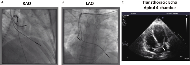
In particular, lead conductor fractures may sometimes be identified in cases of lead failure in the setting of elevated lead impedance. These typically occur at sites of acute angulation or at sites of increased external stress, such as the first rib–clavicular junction in leads placed via subclavian vein puncture or at anchoring sites if a protective sleeve was not applied at the time of implant. Fluoroscopy, in conjunction with traction on the lead and generator, may be required to delineate the fracture. Previously, a manufacturer’s advisory on potential fracture of an inner J-shaped retention wire has recommended periodic ciné-fluoroscopy to evaluate for fracture in certain active fixation J-shaped atrial leads (Telectronics AccufixTM series). Recently, outer insulation breach resulting in exteriorization of conductors has been reported in the St. Jude Medical RiataTM leads, which can be identified on fluoroscopy (Figure 11.5).13
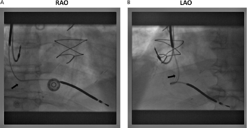
The venous insertion site may be apparent on the film; jugular venous cut-down, for example, entails lead entry superior to the clavicle. Anatomical variants (such as a persistent left superior vena cava) may also be appreciated.
Clues to the polarity of the lead(s) may be appreciated by analyzing either the distal tip for the presence of a ring electrode or the header block, although whether the generator is actually programmed to bipolar or unipolar pacing remains to be determined. Examination of the connector block may disclose retraction of the lead pin or inadvertent reversed connection of the lead pins.
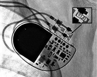
The generator may also be examined for position and, importantly, to identify the specific model in patients with an unknown system. Various radiographic identification codes exist that are manufacturer specific and facilitate recognition of the specific device in question (Figure 11.6). Comprehensive references exist to assist in this process.14 Older systems not employing such radiographic codes may be identified on the basis of generator shape or battery configuration on the radiograph.
Electrocardiography
It is beyond the scope of this chapter to provide a detailed discussion of pacemaker electrocardiography. Rather, a general approach to the use of electrocardiography in assessing pacemaker functioning will be addressed. The 12-lead ECG, both with and without pacing, is a useful tool in pacemaker follow-up assessments. Aside from confirming the pacemaker’s ability to sense and capture, the ECG can provide important information on lead integrity and position. For example, the typical morphology of a RV-paced complex is that of left bundle branch block (LBBB), whereas right bundle branch block (RBBB) morphology may suggest left ventricular (LV) pacing, whether intentional (e.g. epicardial wires or coronary sinus pacing) or otherwise (e.g. perforation or lead placement in the LV through a patent foramen ovale or the arterial system). A superior axis is common in leads in the RV apex, whereas intermediate or inferiorly directed axes are suggestive of leads high on the septum or in the outflow tract.
The ECG is especially important in follow-up of CRT devices, to determine the presence or loss of LV capture. Since the morphology of LV and biventricular pacing can be quite variable in different patients, it is essential to keep a record of the post-implantation ECGs for comparison.
Fusion and pseudofusion can be identified on the ECG. This information can be valuable in appropriate programming. The atrioventricular (AV) delay may be lengthened to minimize pacing and conserve battery life, or it may be shortened to force pacing [e.g. in CRT devices or in hypertrophic cardiomyopathy (HCM) patients with obstruction].
Magnet Application
The response to magnet application differs between pacemakers and ICDs (Table 11.6). Within pacemakers or ICDs, it varies between different manufacturers, and even among various models of a single manufacturer.15 A doughnut magnet with a strength of around 90 Gauss is typically used for this purpose.
| Pacemakers | ICDs | |
|---|---|---|
| Typical magnet response |
|
|
| Programmability |
|
|
| Special functions Uses |
|
|
BS, Boston Scientific; EMI, electromagnetic interference; SJM, St. Jude Medical.
Table 11.6 Responses and uses of magnet application over pacemakers and ICDs
For pacemakers, magnet application typically results in asynchronous pacing by closing a magnetic switch (mechanical reed switch, Hall sensor, or giant magnetoresistive sensor). It is a frequent misconception that magnets “turn off” pacemakers when quite the opposite ensues. The magnet pacing rate and other elements of the magnet response are manufacturer specific and sometimes vary among different models of a single manufacturer. The magnet pacing rate decreases in all pacemakers (the exact value is manufacturer and device specific) when the device reaches elective replacement indicator (ERI), and decreases further at end of life (EOL). This has long been the basis of trans-telephonic monitoring for battery depletion in pacemakers. ERI in some models may be elicited only in the magnet mode. In such instances, routine magnet application may be especially important for determining the need for replacement of a depleting pacemaker generator. Magnet response is programmable in some pacemakers.
Although multi-programmability and telemetered data through the programmer have supplanted magnet application for detailed pacemaker analysis in most cases, magnet application remains an important aspect of pacemaker evaluation. In the absence of a programmer, magnet application with ECG monitoring confirms the ability to capture a cardiac chamber during asynchronous pacing. This may otherwise not be apparent if the patient’s intrinsic rhythm inhibits pacemaker firing. Because pacemakers typically respond to magnet application by asynchronous pacing, magnets may also be employed, both diagnostically and therapeutically, in cases where potential pacemaker malfunction is attributed to sensing problems. Magnet application can be therapeutic to terminate PMT or to restore pacing in cases of oversensing. In cases of pacemaker dependence, rapid magnet conversion to asynchronous pacing may be critical in preventing asystole due to oversensing or cross-talk inhibition (particularly if the appropriate pacemaker programmer is unavailable). In some contemporary pacemakers, however, magnet application may instead trigger specialized pacemaker functions, such as threshold search, EGM storage, or no response in programmable devices with the magnet response turned “off.”
For ICDs, magnet application suspends tachyarrhythmia detection and therapy, but typically does not affect pacing (the exception is Sorin devices). With most current ICDs, tachyarrhythmia detection and therapies are restored upon removal of the magnet. However, with some older devices (Boston Scientific) magnet application for a certain period of time may result in permanent deactivation of tachyarrhythmia functions. As with pacemakers, magnet response is programmable in some ICDs.
The application of a magnet over the generator is rarely associated with adverse effects. On occasion, ventricular ectopy may result from asynchronous ventricular pacing, but this is seldom sustained.
Pacemaker Dependence
Pacemaker dependency is defined as the absence of a life-sustaining rhythm without the pacing system. Cessation of pacemaker function in these patients may result in symptomatic bradycardia or ventricular asystole that endangers the life of the patient. The term is problematic for a variety of reasons. First, it is often misused in cases when 100% pacing is observed. In this sense any patient with a pacemaker may be rendered “pacemaker dependent” by having the device programmed to a rate greater than their intrinsic heart rate. Second, in patients with conduction abnormalities such as AV block, the degree of impairment may vary from one point in time to another. That is, the ability to conduct 1:1 from atrium to ventricle may be somewhat “whimsical” and may also vary with the application of various medications that facilitate or depress conduction (Figure 11.7). Finally, with reprogramming of pacemakers to slower rates, gradual slowing of the pacing rate is more likely to allow the emergence of an escape rhythm than is a sudden cessation of pacing (Figure 11.8).
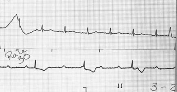

In patients in whom gradual reprogramming of the generator to slower rates still results in 100% pacing at the slowest programmable rate, it is still possible to determine the presence (or absence) of an underlying rhythm if the output is temporarily inhibited or programmed to subthreshold values. This practice may result in prolonged asystole during programming and should be attempted only if temporary programming is available that is rapidly reversible. Alternatively, chest wall stimulation may be applied with alligator clip cables from a temporary pacing device via skin electrodes (one situated directly over the generator can) in an effort to produce EMI and thereby inhibit pacer output. This technique is particularly well suited to unipolar systems with limited programming capabilities for rate or output.
Functional pacemaker dependence is a term that is sometimes applied to patients with CRT devices who develop acute hemodynamic deterioration when CRT is inhibited, because of reversion to a dyssynchronous state of electrical activation. The term may also be used for patients who are not usually pacemaker dependent, but may become pacemaker dependent in certain situations (such as sedation, vagal stimulation, anesthetic use, etc.).
Device Interrogation
Programmers and Telemetry
Pacemaker and ICD programmers are complex devices with which the device physician must be thoroughly familiar.5 All programmers, independent of the manufacturer, share certain architectural features. All modern programmers are computer based. There is an input section that allows operator interface with the computer programmer via a keyboard, light pen, and/or touch-sensitive screen. There is a telemetry interface associated with the programmer, usually in the form of a handheld wand that transmits signals to and receives data from the pulse generator. Wireless communication between the programmer and the device is available for some devices. The programmer is also associated with a printer for hardcopy printouts of pacemaker data. The printer may be physically integrated with the programmer or be a separate component.
Telemetry is the ability to transmit information from one device to another. Current programmers enable bidirectional telemetry (two-way communication) with the device. There are broadly two modes of communication between the device and the programmer. First, near-field or inductive telemetry requires placement of a handheld wand connected to the programmer directly over the device. Communication is based on inductive coupling between two closely placed coils, one in the device and the second in the wand. Second, several current devices are capable of wireless telemetry with the programmer up to a distance of about 10–20 feet from the device without needing a wand; however, initial communication between the device and the programmer through the handheld wand is required as a security measure before wireless telemetry can be established. Both near-field and wireless telemetry utilize radiofrequency (RF) for transmission. The longer range wireless telemetry utilizes either the ISM band (902–928 MHz) or the MICS band (402–405 MHz) of the RF spectrum; the carrier frequencies depend upon the manufacturer.
The ability to undertake telemetry, as in the case of programming, is device specific and requires manufacturer-specific programmers and/or modules. Inability to perform telemetry has several potential explanations, including using the wrong programmer, using the correct programmer but without the software updates to communicate with the present model of device, an older model of device incapable of providing telemetry, or a device that has a circuit malfunction16 or is at end of life.
Spurious programming remains a problem that may present in a variety of forms. “Phantom programming” refers to the reprogramming of a device by another physician unbeknown to the original physician programmer. “Dysprogramming” is spurious programming due to an anomalous interference source such as electrocautery. “Misprogramming” is reprogramming of a device by a programmer in unanticipated fashion due to faulty program emission counts. Rarely, “cross-programming” may be observed as the unpredictable reprogramming of one manufacturer’s pacemaker or ICD by another manufacturer’s programmer. For this reason, a pacemaker or ICD must be interrogated and programmed only with the specific manufacturer’s programmer.
Approach
Programmers enable both programmability and telemetry of a host of data, including programming commands, administrative data, programmed data, measured data and diagnostic data (Table 11.7). Device follow-up assessments can be performed efficiently using a systematic approach (Table 11.8).
| Administrative data (patient information) Programmed parameters Measured (real-time and stored) data Diagnostics (stored data) Electrograms and event markers (real-time and stored) |
Table 11.7 Data obtained by telemetry
|
Table 11.8 Approach to device interrogation
Review of Programmed Parameters
Even before any reprogramming is undertaken or thresholds are determined, the device should be interrogated to document the current programmed settings. All modern devices have such telemetry available. It should be emphasized that independent confirmation of parameters such as mode and rate should be made electrocardiographically after all interventions, because telemetry will not always reflect true programmed settings, although this is rare. This is particularly true in the case of device systems that have come into contact with extreme environmental noise (such as electrocautery or defibrillation), causing subsequent resetting of the device or device malfunction—in these cases, what one sees (via telemetry) is not always what one gets.
Some models allow both programmers and generators to have actual times displayed, which is important in programming certain circadian features, as well as in identifying when certain events, such as automatic mode switching, have occurred since the last interrogation.
Display of Real-Time EGMs, Marker Channels, and ECG
Real-time intracardiac EGMs and marker channels may be available, depending on the system used; they facilitate the physician’s ability to diagnose appropriate, or inappropriate, device function. Displaying the appropriate real-time EGMs and marker channels along with one or more ECG leads facilitates device interrogation.
Intracardiac EGMs
Intracardiac EGMs are the signals recorded by electrodes located on the pacing leads. They may be displayed in real-time (real-time EGMs), or the signals from past events stored by the device may be telemetered (stored EGMs). It is important to note that the telemetered EGM may not always be the same as the signal used by the sense amplifier. The size of the intracardiac EGMs may give the physician a rough idea of the sensing capabilities of the system and may also delineate the amplitude of far-field signals. During device interrogation, it is important to ensure that the appropriate real-time EGMs from the chamber of interest (atrial, RV, or LV) for the particular situation are displayed. With most devices, one can choose from various options such as bipolar, unipolar tip, and unipolar ring EGMs. The clinical utility of intracardiac EGMs includes identifying retrograde conduction, measuring VA conduction time, assisting rhythm identification, evaluating unusual sensing phenomena, evaluating lead connector integrity, assisting threshold determinations, and evaluating myopotential sensing.
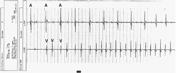
In addition to real-time EGMs, with some devices the patient may freeze and store EGMs with external magnet application during symptomatic events, or the device may automatically store EGMs in response to high heart rates (Figure 11.9). This corresponds to an event monitor function of the device. These stored EGMs are discussed later in “Review of patient diagnostics.”
Marker Channels (Event Markers)
Marker channels (event markers) are potentially more useful than EGMs, and denote when a particular channel (atrial or ventricular) is sensing activity or emitting a paced output (Figure 11.10). By telling the physician what the device is “seeing and doing,” certain phenomena, such as cross-talk inhibition, may be more easily defined. However, event markers do have their limitations. They describe device behavior, but not its appropriateness; in addition, a stimulus output report does not necessarily imply capture. Event markers are best used in conjunction with a simultaneously recorded surface ECG and/or EGM. Just like EGMs, marker channels may be displayed in real time or for stored episodes.
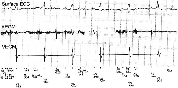
ECG
It is useful to record at least one real-time ECG lead during device interrogation. This is especially important in pacemaker-dependent patients during threshold testing where local myocardial capture seen on the intracardiac EGM may not necessarily imply global capture. In addition, the ECG is useful in confirmation of oversensing in conjunction with the intracardiac EGM and event markers. Evaluation of CRT devices often requires a 12-lead ECG to assess the degree of electrical resynchronization.
Most programmers have the capability to display multiple ECG leads using skin electrodes. ICDs can display far-field EGMs (shock EGMs) of different configurations that can serve as a surrogate for a surface ECG lead. Several newer devices use these far-field EGMs to generate a “leadless ECG” without requiring placement of skin electrodes. An external ECG machine may be used, especially if a 12-lead ECG is warranted.
Evaluation of Measured Data, and Pacing and Sensing Thresholds
Measured data include parameters that indicate the status of the battery and of the lead(s). Sensing and pacing thresholds, which are in fact a type of measured data, indicate lead status. Measured data (including thresholds) can be evaluated in real time; in addition, historical data can be stored and displayed as “trends” in most devices. The retrieval of stored and real-time data indicating battery and lead status is an important part of each follow-up visit (Table 11.9).
| Battery | Lead |
|---|


