X-ray Coronary Angiography
Peter Lanzer
X-ray angiography, despite its limitations, is the sole means of guidance used in the vast majority of coronary interventions. Intracoronary ultrasound imaging (Chapter 3C) and flow/pressure wire measurements (Chapter 3D) are additionally employed in <5% of procedures. The limitations of x-ray coronary angiography have been discussed extensively (for review, see reference 1). The luminographic and projectional character of the technique that is associated with the inability to visualize arterial walls, the actual seat of coronary atherosclerosis, and the inability to accurately visualize lesions, the actual target of interventions, are considered the two major drawbacks. However, the high image resolution, the robustness of image acquisition, and the on-line availability of images combined with instant fluoroscopic imaging make x-ray angiography seem indispensable as a first-line imaging tool in peri-interventional settings.
Because the operator is unable to view the interventional site directly, he must rely entirely on interpretation of angiographic images throughout the entire percutaneous coronary intervention (PCI) process. The diagnostic quality of periprocedural coronary imaging depends on operator-independent factors (e.g., the quality of the available imaging equipment) and operator-dependent ones (e.g., the ability to acquire optimal projections, image interpretation). Operator-independent factors have been described elsewhere (for review, see reference 2) and are not reviewed in the context of this chapter. Here, selected, critical, operator-dependent factors relevant to diagnostic quality of coronary images are reviewed.
Periprocedural Coronary Angiography and Fluoroscopy
It is assumed that the reader is familiar with the established standards concerning the operation of an interventional catheterization laboratory3 and radiation safety.4 In PCI settings, diagnostic x-ray coronary angiographic images are critical for establishing the indication, for determining revascularization strategy, for the real-time monitoring of the interventional site throughout the intervention, and for documentation of the results. During the main interventional cycle, fluoroscopic images and cine angiograms are acquired after each interventional step. On the basis of image interpretation, each subsequent procedural step is planned or the procedure terminated (see chapter 4). To fully assess the interventional site using angiography, there must be complete visualization of the target lesion, adjacent segments and side branches, proximal and distal target vessel, dependent microcirculation, and nontarget (“bystander”) coronary arteries. Optimum visualization and consistent image interpretation allow successful interventions. Suboptimal image quality and interpretation set the stage for impending disasters. Table 3B-1 summarizes the individual components required to fully assess the PCI site.
Target Vessels and Target Segments
Despite numerous attempts to date,5,6,7,8,9 no standard nomenclature of coronary arteries and coronary artery segments is available. To avoid confusion, only a basic terminology reflecting the major patterns of coronary artery ramifications will be used in this chapter (Table 3B-2).10 To optimally visualize coronary arteries, typical projections (“coronary views”) should be employed in diagnostic coronary angiography.11,12 To unequivocally identify individual projections, side (left and right) and angulation (degrees) are given. Angulation of the x-ray beam in craniocaudal and left-to-right directions is indicated by referring to the position of the image intensifier with respect to the patient. All positions of the image intensifier toward the head of the patient (headward from the transverse planes) are termed
cranial; all positions of the image intensifier toward the feet of the patient are termed caudal. All positions of the image intensifier between frontal and lateral positions are termed anterior oblique, and the specification “right” or “left” is added depending on the side. Table 3B-3 shows an example of the recommended diagnostic coronary angiography projections. However, the recommended “coronary views” frequently need modifications to permit optimal definition of target sites in individual patients. During interventions, recommended views are even less useful, and individual angulations for each target lesion must be individually sought and identified. These views are then maintained throughout the intervention. To allow consistent documentation of the initial findings, all the relevant intermediary steps, and the final results, it is
recommended that a standard imaging protocol be adopted. Table 3B-4 provides an example of the suggested coronary artery projections for angiography-guided PCI. Table 3B-5 provides an example of a standard angiography protocol to document PCI results. In Figure 3B-1, coronary artery segmentation is presented according to the American Heart Association nomenclature. Figure 3B-2 is an example of standard coronary angiographic projections.
TABLE 3B-1. Targets of Cine Coronary Angiography and Fluoroscopy in PCI and the Corresponding Types of Information to be Acquired and Stages of the Procedure Affected | |||||||||||||||||||||||||||
|---|---|---|---|---|---|---|---|---|---|---|---|---|---|---|---|---|---|---|---|---|---|---|---|---|---|---|---|
| |||||||||||||||||||||||||||
TABLE 3B-2. Ramification Patterns and Basic Nomenclature of Coronary Arteries | ||||||||||||||||||||||||||||||
|---|---|---|---|---|---|---|---|---|---|---|---|---|---|---|---|---|---|---|---|---|---|---|---|---|---|---|---|---|---|---|
| ||||||||||||||||||||||||||||||
TABLE 3B-3. Suggested Coronary Artery Projections for Diagnostic Angiography | ||||||
|---|---|---|---|---|---|---|
|
TABLE 3B-4. Suggested Coronary Artery Projections for Angiography-guided PCI | ||||||||||||||||||||||
|---|---|---|---|---|---|---|---|---|---|---|---|---|---|---|---|---|---|---|---|---|---|---|
| ||||||||||||||||||||||
TABLE 3B-5. Example of a Standard Angiography Protocol for Documentation of PCI Results | ||||||||||||||||||||
|---|---|---|---|---|---|---|---|---|---|---|---|---|---|---|---|---|---|---|---|---|
| ||||||||||||||||||||
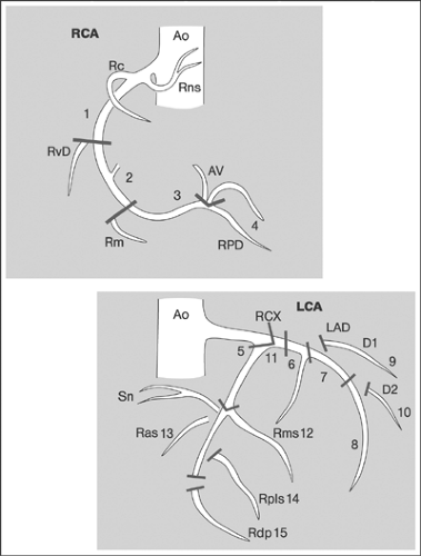 FIGURE 3B-1. American Heart Association nomenclature of coronary artery segments. (Modified from Erbel R, et al. Richtlinien der interventionellen Koronartherapie. www.dgk.org/leitlinien, accessed August 12, 2005.) |
Target Lesions
Target PCI lesions are located in the epicardial segments of the coronary arteries that are >2 mm in diameter. Predilection sites include the proximal third,13,14 bifurcations,15 and inner sides of curved segments.16 Besides major cardiovascular risk factors, regional flow disturbances are thought to be a cause of
coronary atherosclerosis at predilection sites.17 Because of the diffuse character of coronary atherosclerosis, several potential target lesions may be present at different coronary sites. Furthermore, multiple plaque ruptures may be documented in individual patients.18
coronary atherosclerosis at predilection sites.17 Because of the diffuse character of coronary atherosclerosis, several potential target lesions may be present at different coronary sites. Furthermore, multiple plaque ruptures may be documented in individual patients.18
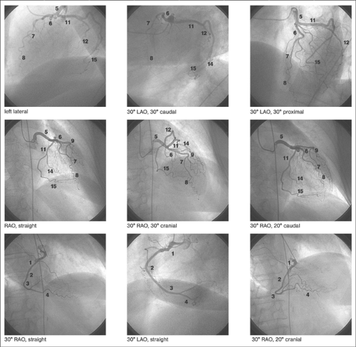 FIGURE 3B-2. Example of typical angiographic coronary artery projections. Typical projections of the left and right coronary arteries are shown. The numbers correspond to the American Heart Association coronary artery segment classification. (See Fig. 3B-1.) |
Quantitative Assessment
The initiation, continuation, and termination of PCI depend on the angiographic and/or physiologic definition of the hemodynamic significance of target lesions. The hemodynamic significance of lesions depends on the magnitude of coronary flow and is determined by a number of factors including the severity, length, geometric shape, dynamic behavior of the stenosis and interactions with the microcirculations.19,20 The hemodynamic impact of fixed stenoses is proportional to the transstenotic pressure gradients ΔP at different coronary flow (CF) levels. Ex vivo measurements showed that ΔP/ΔCF [mm Hg/cm3 per minute] begins to rise steeply for stenoses whose diameter is >60% of the diameter, whereas resting blood flow begins to fall at stenoses >80% in diameter.21 Clinically, estimates of the hemodynamic severity of coronary lesions have been primarily based on measurements of the degree of maximum narrowing visualized by angiography. However, these estimates are inaccurate because of the geometric complexity and variable dynamic behavior of in vivo stenoses, which frequently
leads to under- or overestimation of the true hemodynamic severity.22 In addition to the degree of narrowing, the length of the stenosis is another important determinant of its hemodynamic relevance. However, in clinical practice, measuring the length of the stenosis has primarily been used to size dilatation devices such as balloons and stents not to determine the hemodynamic relevance of lesions.
leads to under- or overestimation of the true hemodynamic severity.22 In addition to the degree of narrowing, the length of the stenosis is another important determinant of its hemodynamic relevance. However, in clinical practice, measuring the length of the stenosis has primarily been used to size dilatation devices such as balloons and stents not to determine the hemodynamic relevance of lesions.
The severity of a stenosis can be determined angiographically by means of visual estimations or quantitative measurements using computer-assisted analysis. Visual estimation is associated with high intra- and interobserver variability.23,24 Quantitative, edge detection, or video-densitometry-based coronary angiography (QCA) provides consistent and highly reproducible results.25,26 To facilitate QCA measurements during PCI, on-line modules allowing the direct measurement of the severity, length, and geometric profile of lesions are available. In lesions with angiographically indeterminate hemodynamic relevance, added flow/pressure and/or intravascular ultrasound (IVUS) measurements may be performed.27
The severity of coronary stenoses is measured as a percentage reduction in the nominal diameter of the target vessel (%D) using the formula %D = Ds/Dn × 100, where Ds designates the minimum diameter of the stenosis, measured as the shortest distance between opposing endoluminal edges at the narrowest point (neck) of the lesion, and Dn designates the nominal diameter of a reference segment that is adjacent, usually proximal, and unobstructed. Lesions in which the coronary stenosis represents at least 70% of the vessel diameter are usually considered significant and represent a target for revascularization. Lesions with <50% diameter stenosis are considered insignificant and are treated medically. Intermediate lesions with 50% to 70% diameter stenosis are considered “borderline,” and additional means are required to determine their hemodynamic significance. However, in the literature stenoses >50% diameter are also sometimes called significant, particularly when the left main coronary artery and bifurcation lesions are concerned. Lesions with >95% diameter stenosis are termed subtotal occlusions. In the left main coronary artery and in bifurcation lesions, critical stenoses are considered to be present where the reduction in diameter exceeds 50%. The presence of lesions with >50% diameter stenosis in one or more major coronary arteries determines whether the status of coronary artery disease is defined as one-, two-, three-, or multiple-vessel disease.28 The length of a stenosis is determined angiographically as the distance between the points of transition between the luminal irregularity of the lesion and the smooth endothelial interface of the healthy adjacent segment. Lesions <5 mm in diameter are considered focal; those >20 mm are considered diffuse.
Qualitative Assessment
Since the impact of the morphology of coronary lesions on outcome was recognized, attempts were made to classify lesions systematically on the basis of their angiographic appearance. The most frequently employed classification, proposed by the American College of Cardiology and the American Heart Association,29


Stay updated, free articles. Join our Telegram channel
Full access? Get Clinical Tree
