Venous Diseases
Zubin Irani
John A. Kaufman
Image-guided interventions performed on the venous system of the body encompass a broad anatomic distribution. A practical “how-to” approach to management of these problems is covered in this chapter. Initially some generalities are offered applicable to nearly all procedures, followed by a regional approach to venous disease and interventions. Also covered are the various devices that are placed in the often-normal venous system to aid in patient management.
Pathology
Venous disease may arise from extrinsic compression. When this is chronic, such as in benign compressive syndromes, intramural intimal hyperplasia develops that further compromises the lumen, which can ultimately occlude from superimposed thrombosis. The specific etiologies and syndromes are described in the relevant sections. Central venous access catheters themselves narrow the lumen, and pericatheter thrombosis causes further narrowing. Otherwise, thrombosis of a normal vein can occur in a systemic procoagulant state.
The luminal narrowing impedes venous outflow, and given time, the body can compensate by developing collateral pathways to help in venous return to the point where the collaterals can be responsible for all the venous return when the main vein becomes occluded by superimposed thrombosis. Thrombus extension into the collaterals compromises venous return, and the acute venous hypertension that develops leads to edema, which, if left untreated, can be fatal in the brain and leads to organ dysfunction in the liver and kidneys. In the extremities, swelling is noted. Over time, this persistent venous hypertension leads to varicose veins and skin ulcerations, especially in the lower extremities. Thus presentations reflect the severity of the lesion and the acuity of its onset, along with the status of collateral pathways.
Presentations
Inquire about the presenting complaint. An asymptomatic patient cannot be made to feel any better no matter how abnormal the images appear. Patients complain of swelling and pain in the draining territory of the abnormal vein. Acute onset of symptoms suggests occlusion from thrombosis. Look for edema in the extremities, and if present document the limb circumference. This can be used as an objective marker of improvement. Always examine the arterial pulses as well. Keep in mind the other causes for swelling such as lymphedema and heart failure. Skin changes such as varicosities and prominent collaterals, discolorations, and ulcerations should be sought. The aims here are to review the clinical data, make a diagnosis, and generate a treatment plan.
Imaging Findings
Ultrasound
A normal vein is completely compressible on ultrasound examination Fig. 14-1, and Doppler interrogation shows respiratory variations and flow augmentation with distal compression. The latter two indicate no obstruction downstream (central) to the probe. The key finding for DVT is to visualize the thrombus within the vein Fig. 14-2; acute thrombus can be echogenic, isoechoic, or hypoechoic to blood. Thus, this sign is not always present. Thrombus within a vein will prevent that vein from being completely compressed, and this is very diagnostic of thrombus acutely, especially if the compression collapses the artery and not the vein. Other findings include loss of respiratory variations and no flow augmentation on Doppler interrogation; in the absence of any local vein abnormality, the latter two indicate obstruction downstream of the probe.
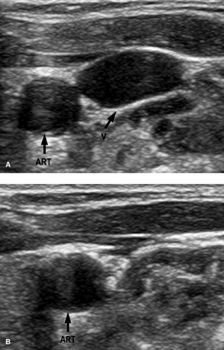 FIGURE 14-1. Effect of compression on normal vein. A: No compression on vein (V). B: With compression. Notice how the normal vein is obliterated. ART, artery. |
 FIGURE 14-2. Ultrasound of deep vein thrombosis (DVT). A: Gray-scale long-axis image showing echogenic thrombus (arrows) within lumen of common femoral vein. B: Cross-sectional image without compression showing echogenic clot (white arrow) in the vein (V). C: Cross-sectional image with compression. Note that the vein (V) does not obliterate even though the artery (ART) has a reduced caliber. Compare this to Figure 14-1. |
Computed Tomographic Scan
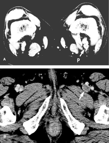
CT with IV contrast usually shows a narrowed or absent contrast column in the affected vein Fig. 14-3. A filling defect suggests thrombosis. CT also provides a look at the immediate surrounding tissues, which may show benign or malignant lesions causing compression of the vein.
Venography
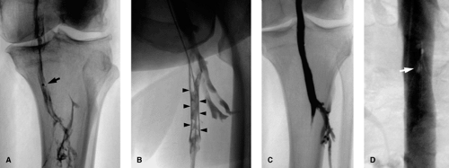
Occlusions cause a complete cutoff in the contrast column, whereas stenosis causes a narrowing. Extrinsic compression typically yields a smooth margin at the stenosis; intramural pathology may in addition yield an irregular margin at the stenosis. Acute thrombus is frequently seen as a smooth intraluminal filling defect in more than one view, with occasionally a meniscus. With clot retraction, a “railroad track” sign Fig. 14-4 is seen, which represents contrast filling between occlusive clot and the vein wall. With chronicity, the vein wall is irregular and narrowed and collateral pathways are demonstrated. Abrupt onset of disease does not give the body a chance to open up collateral channels. Specific findings are discussed in their relevant sections.
Treatment
Treatment options include medical therapy, such as anticoagulation, open surgery such as vein bypass, open thrombectomy, and image-guided interventions, discussed later. It is important to have a management plan prior to starting. The steps in image-guided interventions include venous access and performing diagnostic venography. Once a decision to perform an intervention is made, heparin is given (5000 U bolus) and the lesion is crossed with a guidewire. From here a sheath is positioned for angioplasty or stent placement, or, for thrombolysis treatment, an infusion system is introduced over the guidewire. These are discussed in detail.
Venous Access (Puncture)
All cases begin with accessing the venous system. Access can be obtained using surface/anatomic landmarks or image guidance, usually ultrasound (Fig. 14-5, Table 14-1). Study the planned vein of access with ultrasound, looking for the vein to be compressible with a hypoechoic lumen and having Doppler flow signal within it. These suggest a patent vein. An incompressible vein with echogenic lumen and no Doppler flow indicates an occluded vein. One can work through an occluded vein, but if this is not possible, then alternative access sites should be used. No matter what the guidance, sterile technique is used and local anesthesia infiltrated in area of access prior to skin incision and access needle introduction.
Either micropuncture (21G) or larger gauge needles can be used to enter the veins, through which guidewires can be passed (Table 14-2). Micropuncture access kits have a 0.018-in. wire, which passes through the needle, and the needle is exchanged out over the 0.018-in. guidewire for an introducer and sheath, which has an inner 3F sheath and an outer 4F or 5F sheath. The outer sheath can accept 0.035- or 0.038-in. guidewires over which it can be exchanged out for a larger diameter sheath or catheter depending on the procedure Fig. 14-6. The same steps are followed if working through an occlusion. Once the needle tip is confirmed to be within the lumen (thrombus), the guidewire is introduced and advanced through the clotted segment into the patent segment of vein.
Augmentation Maneuvers
In cases where the vein is collapsed, the patient can be asked to perform a Valsalva maneuver or can be placed in an appropriate dependent position to help distend the vein for better
visualization and cleaner access. For jugular access, a Trendelenburg position is used and the reverse for femoral vein access.
visualization and cleaner access. For jugular access, a Trendelenburg position is used and the reverse for femoral vein access.
TABLE 14-1. Steps in Ultrasound Guided Venous Puncture (Access) | |
|---|---|
|
TABLE 14-2. Troubleshooting Guidewire Difficulties During Venous Access | ||||||
|---|---|---|---|---|---|---|
|
Complications
Complications (Table 14-3) are typically related to inadvertent adjacent structure injury by the needle tip, usually related to poor or no image guidance being used during access.
Venography
This is used to define anatomy or pathology and is the starting diagnostic component of any image-guided procedure. The desired access site is usually “upstream” of the point of interest. Always bear in mind that more than one access site maybe needed to fully define an area of abnormality. Quantitative analysis of the venogram is performed with particular attention to the length of the diseased segment of vein and to the diameter of the normal vein before and after the abnormal segment and of the stenosis, if present. A measuring pigtail catheter or a radiopaque ruler placed in the field of view at the time of imaging can be used to perform quantitative analysis of the images where intervention is planned. With imaging software packages available today, direct measurements can be made. Note is also made of degree of collateral pathway filling. In mild stenosis, manometry (see later section) can be performed to further characterize the hemodynamic severity of the abnormality. In cases where there is a contraindication to using iodinated contrast agents, alternatives include gadolinium or carbon dioxide.
Upper Extremity Veins
Indications are listed in Table 14-4. Upper extremity venography is performed employing the digital subtraction angiography (DSA) imaging technique by hand injection of contrast into the venous system accessed with an 18- to 20-gauge needle or angiocath in the superficial veins on the dorsum of the hand, the cephalic vein, or its tributaries. If injecting via the cephalic system does not yield opacification of all the venous channels of the arm, then flow can be diverted from the
cephalic into the basilic and deeper channels by applying a tourniquet above the elbow. A 20-mLmL saline “chaser” bolus can be used immediately after contrast injection to flush contrast through the veins for better imaging. If the area of interest is the more central veins (axillary, subclavian, innominate veins), then an antecubital vein or, using ultrasound guidance, the brachial or basilic veins can be accessed. If diagnostic-quality imaging is still not obtained, large-volume injections closer to the point of interest will be needed via a diagnostic (flush type) catheter using a power injector. An 18-gauge IV line will accept a 0.035-in.-diameter guidewire, over which an exchange is made for a “flush” straight or pigtail diagnostic catheter positioned close to the area of interest. Should contrast not flow easily through the axillary-subclavian vein into the brachiocephalic vein, a repeat venogram with the arm elevated is performed to show that there is no mechanical impediment to flow of contrast.
cephalic into the basilic and deeper channels by applying a tourniquet above the elbow. A 20-mLmL saline “chaser” bolus can be used immediately after contrast injection to flush contrast through the veins for better imaging. If the area of interest is the more central veins (axillary, subclavian, innominate veins), then an antecubital vein or, using ultrasound guidance, the brachial or basilic veins can be accessed. If diagnostic-quality imaging is still not obtained, large-volume injections closer to the point of interest will be needed via a diagnostic (flush type) catheter using a power injector. An 18-gauge IV line will accept a 0.035-in.-diameter guidewire, over which an exchange is made for a “flush” straight or pigtail diagnostic catheter positioned close to the area of interest. Should contrast not flow easily through the axillary-subclavian vein into the brachiocephalic vein, a repeat venogram with the arm elevated is performed to show that there is no mechanical impediment to flow of contrast.
TABLE 14-3. Access Complications | |
|---|---|
|
TABLE 14-4. Indications for Arm/Central Venography | |
|---|---|
|
Superior Vena Cava
The superior vena cava (SVC) and its innominate tributaries are best visualized by utilizing the DSA imaging technique and performing simultaneous power injections following catheterization with 5F multi-side-hole catheters of the axillary or subclavian veins via ultrasound-guided basilic or brachial vein access. The entire chest and mediastinum are imaged to include collateral circulation. In case of SVC occlusion, the in-ferior aspect of the occlusion is defined by catheterization into the occluding lesion of the SVC via the right atrium from a femoral route.
Lower Extremity Veins
Indications are listed in Table 14-5. Lower extremity venography is performed employing digital imaging technique by hand injection of contrast after securely accessing the venous system with a 19- to 23-gauge needle or angiocath in the superficial veins on the dorsum of the foot or the superficial vein of the great toe. The patient is placed in a semierect position (45 to 60 degrees) on a tilting radiographic table. To avoid any artifacts from muscular compression, especially at the popliteal vein, and to obtain opacification of the deep and muscular system of the calf, the involved leg is put in a non-weight-bearing position by elevating the uninvolved leg on a box 10 to 20 cm in height. A tourniquet is applied above the ankle and the knee to improve opacification of the deep system, and any compression artifacts from these should be noted. Images are acquired (Table 14-6) along with monitoring for possible flow of contrast from the deep to the superficial system via incompetent perforators after injecting 100 to 150 mL of diluted contrast (half saline, half contrast) and following the contrast column up the leg (ascending venography). The degree of table tilt is adjusted to help control the flow of contrast. Improved opacification of the thigh and pelvic veins can be obtained with a saline “chaser” bolus along with forcible plantar flexion of the foot.
TABLE 14-5. Indications for Ascending Leg Venography | |
|---|---|
|
TABLE 14-6. Images in Ascending Leg Venography | ||||||||||||
|---|---|---|---|---|---|---|---|---|---|---|---|---|
| ||||||||||||
With respect to vein access, warm compresses applied to a dependent foot can help accentuate collapsed veins, whereas applying elastic bandaging 30 to 60 minutes prior to beginning, to a foot that has been elevated for hours, can help reduce swelling. Ultrasound guidance should be used in difficult cases. Rarely, surgical cutdown is needed.
Inferior Vena Cava and Iliac Veins
The inferior vena cava (IVC) is best visualized by utilizing the DSA imaging technique and performing power injection following catheterization of the inferiormost IVC with a multi-side-hole catheter introduced via either the jugular or femoral routes. The common and external iliac veins are best visualized by direct injections of catheters placed in the inferiormost external iliac vein from an ipsilateral femoral access. For bilateral visualization, both femoral veins are accessed and catheterized as mentioned previously and simultaneous power injections performed utilizing the DSA technique.
Complications
Complications include those that are seen with any procedure, such as those related to access, and contrast reactions, including soft-tissue contrast extravasation in extremity venograms.
Manometry
Pressure measurements either side of the stenosis can be used to obtain a pressure gradient; gradients of 3 mm Hg or less are considered normal. Gradients of 5 mm Hg or more are considered significant and, in a symptomatic patient, indicate a need for some intervention. A pressure transducer is connected to a catheter with side holes, and this catheter is positioned on one side of the lesion while pressure readings are recorded. It is then pulled across the lesion to the other side and pressures recorded again. Alternatively, simultaneous readings can be obtained by placing the catheter connected to a transducer inside a sheath that is also connected to a transducer and is one French size larger in diameter than the catheter, and positioning the catheter on one side and the sheath tip on the other side of the lesion. Simultaneous pressures are recorded.
Venous Stenting
Table 14-7 shows the indications for venous stenting. Self-expanding stents oversized by at least 15% to 20% relative to the normal vein are ideal for use in the venous system. For stent
diameters up to 14 mm (vein diameters no bigger than 12 mm), 7F-diameter sheaths can be employed to deliver the stents. If larger diameter stent sizes are going to be used, then larger sheath diameters will be needed; consider accessing a larger vein to work from such as the jugular or femoral vein. Some stent options are presented in Table 14-8. Generally, moderate oversizing is of no significant consequence.
diameters up to 14 mm (vein diameters no bigger than 12 mm), 7F-diameter sheaths can be employed to deliver the stents. If larger diameter stent sizes are going to be used, then larger sheath diameters will be needed; consider accessing a larger vein to work from such as the jugular or femoral vein. Some stent options are presented in Table 14-8. Generally, moderate oversizing is of no significant consequence.
TABLE 14-7. Indications for Venous Stent Placement | ||
|---|---|---|
|
Crossing the Lesion
By definition, there is a lumen, albeit narrowed, in a stenosis. If large enough, a “J” tip guidewire should be used to navigate through the stenosis; the “J” shape protects from “digging” into the wall of the vein and potentially perforating out the side of the vein. If the lumen does not allow for this, an angled-tip guidewire will be needed to negotiate the stenosis. Either hydrophilic or nonhydrophilic coated guidewires are acceptable. If the guidewire tip adopts a “J” configuration during manipulations, use this configuration to full advantage to navigate through the stenosis for the reasons just mentioned. Using the guidewire in combination with an angled catheter can be more useful where the stenosis is severe.
With an occlusion, closely examine the venogram for any “nipple” that can be a starting point to begin probing with the guidewire. The authors’ preference is to use a hydrophilic-coated angled-tip guidewire, although nonhydrophilic coated guidewires are an acceptable starting point. A guidewire alone does not have enough stiffness to “push through,” and so a catheter is used in collaboration to give support to the guidewire to advance through the occlusion. Some patience and lots of persistence may be required as one employs a to-and-fro spinning and pushing motion on the guidewire using the torque device. The guidewire may advance through easily, or it may advance a small distance and begin to buckle over. If this happens, try to advance the catheter up to the guidewire tip and see whether, with the added support of the catheter, the guidewire will advance further. It may be necessary to do this repeatedly until one is through the other side of the occlusion. Throughout this process, keep in mind the expected course of the vein from the venogram; should the guidewire appear to take an unexpected course, it is a good idea to advance the catheter up to the guidewire tip, remove the guidewire, and perform a gentle hand injection of contrast looking for extraluminal contrast, which will have an amorphous configuration and appear stagnant with poor or slow washout. If this is the case, pull the catheter back to a point where you are confident of being back in the vessel, and try again with the guidewire. This time, look for the guidewire to advance in a different track than before. The guidewire tip has a limited motion while being advanced through the occlusion, but once across the occlusion into a patent segment of vein, the guidewire tip exhibits a more free spinning motion. Once across the lesion, advance the catheter across the occlusion into the patent vein on the other side. If the catheter does not advance easily, try using a hydrophilic-coated catheter or a smaller diameter catheter. For example, exchange a 5F Berenstein for a 4F glidecath. Usually this advances easily. Remove the guidewire, look for blood return from the patent vein, and confirm this with a venogram. With the catheter across, you are in position to place a suitable guidewire to perform subsequent interventions.
TABLE 14-8. Some Self-expanding Stent Options for Venous Use | ||||||||||||||||||||||||
|---|---|---|---|---|---|---|---|---|---|---|---|---|---|---|---|---|---|---|---|---|---|---|---|---|
|
If the starting tools do not appear to be doing the job, exchange for a different guidewire. Try a stiffer or larger diameter guidewire (e.g., 0.038-in. guidewire). If this is unsuccessful, the back end of the guidewire can be used to try and poke a beginning hole into the occluded segment. This involves just a short, sharp jab into the lesion. The region is then probed with the angled guidewire tip. If after trying different combinations and various tools one is still unsuccessful, it may just not be possible to cross the lesion, especially if it has been present for some time. The more chronic the lesion, the tougher the tissue tends to be, and thus the more difficult to cross.
Stent Placement
A sturdy guidewire (“working” wire) is used for subsequent steps. The authors’ preference is to use a nonhydrophilic coated wire, such as a Storq, as the slippery nature of the hydrophilic guidewire makes it very easy to unintentionally lose guidewire position and even lose access across the lesion. With the “working” wire in place, the sheath is positioned close to the lesion and a road-map venogram obtained prior to advancing the sheath across the lesion. With a stenosis, the sheath usually passes across with the introducer. However, with a severe stenosis or occlusion, the sheath may not pass easily, and in such cases predilatation angioplasty will be needed. This creates a lumen large enough to pass the sheath across. Usually a 3- to 5-mm-diameter balloon, corresponding to 9F to 15F size, respectively, is sufficient for this step.
From here, the stent is introduced into the sheath and appropriately positioned with the aid of the road-map image obtained, ensuring that the entire lesion is covered and treated. If more than one stent is going to be needed to treat the lesion, ensure that there is overlap of the stents so that the entire lesion is treated with stents. After deployment, the stent
is then apposed to the vein wall by an angioplasty balloon sized to the diameter of the normal vein, and a follow-up venogram obtained. Study the images to make sure the diseased segment has been treated, that the lumen caliber is >50% of normal, and that there is reduced collateral filling; if manometric readings were done beforehand, obtain follow-up readings. A larger angioplasty balloon can be used to augment the lumen caliber following stent placement. Also, look for filling defects from thrombus formation within the treated segment of vein. This is discussed next.
is then apposed to the vein wall by an angioplasty balloon sized to the diameter of the normal vein, and a follow-up venogram obtained. Study the images to make sure the diseased segment has been treated, that the lumen caliber is >50% of normal, and that there is reduced collateral filling; if manometric readings were done beforehand, obtain follow-up readings. A larger angioplasty balloon can be used to augment the lumen caliber following stent placement. Also, look for filling defects from thrombus formation within the treated segment of vein. This is discussed next.
Complications
Access site bleeding can be controlled by aggressive and prolonged compression. Vein rupture is discussed in a later subsection. Always maintain guidewire access across the lesion, as this can easily allow one to place a covered stent across the rupture to seal over the point of leakage. The steps are the same as for stent placement, with the proviso that the sheath sizes required will be larger and an exchange for a larger sheath will be required. Should there be thrombus at the site of intervention, this fresh clot will respond to directed pulse-spray thrombolysis with adjunctive angioplasty to macerate and clear the clot.
Undersizing can lead to a free-floating stent within the venous system. Self-expanding stents cannot be stretched to a larger diameter with a balloon, and if there is guidewire access through the stent, another larger diameter stent will need to be placed within the free-floating stent to secure the stent. If the stent has migrated or embolized centrally, the stent can then be collapsed and pulled out via sheaths that typically are oversized by 2F to 5F sizes relative to the delivery sheath size, using standard foreign-body retrieval maneuvers with one or more snare devices to grasp the stent at different points. It cannot be overstated that maintaining guidewire access throughout all this is of paramount importance.
Postprocedure Care
Patients are placed on an antiplatelet agent for 6 to 8 weeks. If stent placement is done on the heels of thrombolysis, oral anticoagulation is also commenced, as for treatment of any deep venous thrombosis.
Angioplasty
The steps are the same as for stent placement, with the difference being, instead of introducing a stent the angioplasty balloon is positioned correctly prior to inflating the balloon Fig. 14-7. Make sure the balloon is not within the sheath prior to inflating. Inflating inside the sheath doesn’t help dilate the stenotic vein. The balloon diameter should match the vein diameter, and upsizing by 1 to 2 mm used if there is no response. If the lesion persists despite angioplasty with >50% stenosis, this indicates elastic recoil of the lesion and is a poor indicator for long-term patency, and stent placement may be considered.
Complications
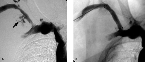
Vein rupture Fig. 14-8 is diagnosed on follow-up venogram in which contrast extravasation is present and can be treated by balloon tamponade, in which prolonged inflation (at least 2 minutes) of the angioplasty balloon is performed against the site of contrast extravasation. This may need to be repeated as often as needed if follow-up venograms continue to show extravasation. A covered stent can also be placed across the site of extravasation to treat the rupture if balloon tamponade is not working, and the steps for this are the same as for any stent placement. In sizing the stent, make sure it is oversized by at least 2 mm in diameter to get a good seal at the site of rupture.
Venous Thrombolysis
Indications for thrombolysis are presented in Table 14-9. Ensure that there is no contraindication to thrombolysis (see Table 14-10). Thrombolysis is best applied to acute thrombus with onset of symptoms within the past 14 days. The aim is to re-establish flow quickly, and mechanical thrombectomy can be performed prior to commencing thrombolysis. Preoperative blood work includes PT, PTT, fibrinogen levels, hematocrit, and platelet counts.
Crossing the Lesion
The steps involved are going to be similar to the other procedures (see the section on venous stenting); define the anatomy/pathology and this will require venous access and a
venogram, cross the lesion using road-map image guidance as described earlier. Usually, the guidewire passes effortlessly through acute soft thrombus.
venogram, cross the lesion using road-map image guidance as described earlier. Usually, the guidewire passes effortlessly through acute soft thrombus.
Administering Thrombolysis
Study the venogram to determine the length of vein that needs treatment. Place the infusion system across the lesion so that entire lesion will be bathed in thrombolytic. The infusion system can be composed of using just one catheter with multiple side holes for infusion, or multiple catheter systems in a coaxial fashion (two or three can be utilized) to bathe a longer segment of thrombus Fig. 14-9. This is better than treating short segments of the thrombus in overlapping fashion by repositioning the catheter with each follow up venogram until the entire thrombus is treated. Once in position, intrathrombotic
lacing using “pulse spray” technique is performed. This involves administering a dose of thrombolytic agent (Table 14-11) in small, short, sharp “pulses” directly into the thrombus. The dose is drawn up in a small syringe (1 to 3 mL), and every 30 seconds a small volume of 0.1 mL or so is “pulsed” into the thrombus. This has the advantage of directly “lacing” the thrombus with the agent, and the “pulsing” theoretically has some mechanical action to cause channels in the thrombus to increase the surface area within the thrombus for the thrombolytic to take effect. The infusion system (Table 14-12) is securely fastened to the patient to maintain position of the infusion system within the thrombus. The thrombolytic infusion is commenced at the chosen rate. Subtherapeutic anticoagulation with a heparin infusion at 500 U per hour following a 2500-U bolus is simultaneously started to prevent further thrombus from forming. Aim for a PTT of 1.5 to 2.0 times normal. If an extremity is being treated, this is elevated above the level of the heart to help with venous return.
lacing using “pulse spray” technique is performed. This involves administering a dose of thrombolytic agent (Table 14-11) in small, short, sharp “pulses” directly into the thrombus. The dose is drawn up in a small syringe (1 to 3 mL), and every 30 seconds a small volume of 0.1 mL or so is “pulsed” into the thrombus. This has the advantage of directly “lacing” the thrombus with the agent, and the “pulsing” theoretically has some mechanical action to cause channels in the thrombus to increase the surface area within the thrombus for the thrombolytic to take effect. The infusion system (Table 14-12) is securely fastened to the patient to maintain position of the infusion system within the thrombus. The thrombolytic infusion is commenced at the chosen rate. Subtherapeutic anticoagulation with a heparin infusion at 500 U per hour following a 2500-U bolus is simultaneously started to prevent further thrombus from forming. Aim for a PTT of 1.5 to 2.0 times normal. If an extremity is being treated, this is elevated above the level of the heart to help with venous return.
TABLE 14-9. Indications for Thrombolysis | |
|---|---|
|
TABLE 14-10. Some Contraindications to Thrombolysis | ||||||
|---|---|---|---|---|---|---|
|
The patient is admitted to a step-down or intensive care unit to be closely monitored for complications. Intravenous punctures and intramuscular injections are avoided.
Follow-up
The infusion system is injected with contrast every 6 to 12 hours to assess for response. Thrombolysis should be stopped if clearance is achieved (>90% thrombus burden cleared), a complication develops, or there is no change in venographic appearance after considerable lysis time. This is a point of diminishing returns, which refers to a time frame beyond which continued thrombolysis only increases risk of bleeding complications with minimal further clot lysis. Rarely is lysis carried out beyond 72 hours; usually, it is stopped at the 48-hour point.
During any of the checks, some maneuvers can be used to mechanically reduce the clot burden and further help pharmacologic thrombectomy. The mechanical thrombectomy methods macerate the thrombus and physically remove the clot from the vein. There are various devices on the market for this. Alternatively, an angioplasty balloon can be inflated within the thrombus to macerate the clot and the inflated balloon can be advanced to push some of the thrombus out of the vein. Size the balloon diameter to be no larger than the vein. To do this, over a guidewire, the infusion system is exchanged out and a sheath is placed that will accept the balloon. If this sheath is going to have a larger diameter than the infusion system, plan to use the infusion system through this sheath; otherwise a hematoma will develop at the access site. Through the sheath a road-map image is obtained to guide balloon positioning. Regular catheters can also be used; if a pigtail catheter can be formed, this is rotated aggressively within the clot. The spinning end of the pigtail scours the thrombus and may also fragment it into smaller pieces. A guidewire can be placed tip-to-tip within the pigtail to offer some robustness to obtain maximum effect.
TABLE 14-11. Some Agents and Suggested Dose Ranges | |||||||||
|---|---|---|---|---|---|---|---|---|---|
|
TABLE 14-12. Possible Infusion Systems | ||
|---|---|---|
|
If during the thrombolysis treatment there are findings to suggest pulmonary embolism, the authors have a low threshold to place a temporary vena cava filtration device in either the IVC for lower extremity lysis, or the SVC for upper extremity lysis. If an underlying lesion is revealed, this will need definitive treatment such as open surgery, angioplasty, or stent placement.
Fibrinogen levels can be measured to follow the systemic effect of the lytic agent, and if this falls below 50% of its initial value or is <100 mg per dL, there is risk of bleeding complication and the lytic dose is decreased, usually halved, until the fibrinogen level returns to a level >100 mg per dL. This practice is not used at the authors’ institution.
Choice of agent is operator or institution dependent. Get comfortable with one or two agents. Following lysis, therapeutic anticoagulation with a vitamin K antagonist is commenced as for any DVT treatment. And a quick point of note is that if one is going to perform stent placement immediately after the thrombolytic treatment, use a new access site to minimize chances of infection.
Results
Early results suggested that systemic IV thrombolysis (streptokinase) had better results for treating DVT than systemic IV anticoagulation (heparin).1 Catheter-directed thrombolysis into the thrombus has better efficacy compared with systemic administration of the lytic agent.2,3 This also results in lower doses being used with lower complications. Although the majority of the reports are on the use of urokinase, some early results of use of other agents suggests that the outcomes are essentially no different from one thrombolytic agent to another.4,5,6,7 Success rates in achieving >50% clot clearance range from 79% to 100%.4,8 See the “Outcomes” subsection in the section on iliac and femoral venous disease for specific results.
Complications
The main complications include bleeding and embolization; in the venous system, this results in pulmonary embolism. For ilio-femoral thrombolysis, the pulmonary embolism (PE) rate in patients who did not receive an IVC filter is on the order of 1%, whereas in those who did have an IVC filter placed, no PE was reported.4,8 Bleeding complications (6% to 25%) were commonest at the access site, followed by retroperitoneal bleeds.4,5,8,9 Kasirajian et al.10 employed mechanical thrombectomy devices
to debulk the thrombus burden prior to thrombolytic administration and reported using far less thrombolytic agent, with no significant bleeding complications. With shorter infusion times and lower thrombolytic doses, it is likely that complication rates will be decreased.11,12
to debulk the thrombus burden prior to thrombolytic administration and reported using far less thrombolytic agent, with no significant bleeding complications. With shorter infusion times and lower thrombolytic doses, it is likely that complication rates will be decreased.11,12
Axillary-Subclavian (Upper Extremity) Venous Disease
Presentations
Etiologies for axillary-subclavian vein disease are listed in Table 14-13. Patients complain of pain and swelling in the ipsilateral upper extremity, and in addition, females may notice breast swelling. Look for a history of central venous catheter placement, malignancy, radiation treatment, dialysis fistulas, and hypercoagulable states. PE from an upper-extremity DVT is uncommon. In the absence of any local cause, a procoagulant state should be sought. Paget-von Schrötter syndrome typically presents in a young patient with axillary-subclavian thrombosis involving the dominant extremity (Table 14-14).
Imaging Findings
Ultrasound
Ultrasound is used to confirm suspected DVT.
TABLE 14-13. Causes of Axillary and Subclavian Stenosis/Occlusion | |||
|---|---|---|---|
|
TABLE 14-14. Features of Paget-Schrötter Syndrome | ||
|---|---|---|
|
CT Scan
A CT scan is obtained if the clinical picture is not typical for thoracic outlet compressive syndrome or catheter-related complication. An IV contrast-enhanced CT of the neck and chest should be reviewed for level of occlusion and presence of collaterals, and for clues to etiology such as cervical ribs, bony exostosis, hypertrophied muscles, or soft tissue masses that may suggest malignancies.
Venography
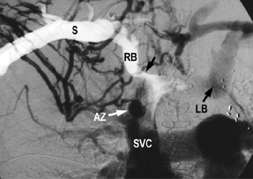
This may show occlusion or stenosis that usually has an irregular appearance as the vein courses behind the clavicle and over the first rib in thoracic outlet syndrome. Important collaterals are listed in Table 14-15, and their presence will indicate an underlying chronic process Fig. 14-10.
Treatment Details
Central venous catheters will comprise the majority of cases. Catheter placement itself narrows the venous lumen, and pericatheter thrombus formation further reduces the lumen caliber. It can provoke intimal hyperplasia, which progresses to narrow down the venous lumen around the catheter. Once this reaches a critical point, the flows are reduced and thrombus
formation occurs, occluding the vein. The catheter traverses the axillary-subclavian vein with the tip (the functional aspect of the catheter) being in the larger, more central veins such as the SVC or even in the upper right atrium. If the catheter is functioning, it is kept in situ and anticoagulation is attempted with heparin and a vitamin K antagonist aiming for an international normalized ratio (INR) in the 2 to 3 range, to prevent thrombus propagation into collateral channels that are critical to the patient at this point. This treatment also protects against possible PE. If there is a contraindication to anticoagulation, catheter removal will be needed. Once the catheter is removed, a luminal channel corresponding to the size of the catheter diameter is now available for blood flow. Most patients will respond to catheter removal. If other access sites are available, one can use these to replace the catheter so patient management can continue. In the few who still have persistent arm swelling, thrombolysis should be attempted. Should there be concerns for pulmonary embolism from an upper-extremity source, an SVC filter can be placed in patients who cannot be anticoagulated. Also remember, stenosis may be related to catheter placement that may have occurred some time in the past, and such patients have a relatively durable response to angioplasty.13
formation occurs, occluding the vein. The catheter traverses the axillary-subclavian vein with the tip (the functional aspect of the catheter) being in the larger, more central veins such as the SVC or even in the upper right atrium. If the catheter is functioning, it is kept in situ and anticoagulation is attempted with heparin and a vitamin K antagonist aiming for an international normalized ratio (INR) in the 2 to 3 range, to prevent thrombus propagation into collateral channels that are critical to the patient at this point. This treatment also protects against possible PE. If there is a contraindication to anticoagulation, catheter removal will be needed. Once the catheter is removed, a luminal channel corresponding to the size of the catheter diameter is now available for blood flow. Most patients will respond to catheter removal. If other access sites are available, one can use these to replace the catheter so patient management can continue. In the few who still have persistent arm swelling, thrombolysis should be attempted. Should there be concerns for pulmonary embolism from an upper-extremity source, an SVC filter can be placed in patients who cannot be anticoagulated. Also remember, stenosis may be related to catheter placement that may have occurred some time in the past, and such patients have a relatively durable response to angioplasty.13
TABLE 14-15. Key Collateral Pathways in Stenosis/ Occlusion of Upper Extremity Veins | ||
|---|---|---|
|
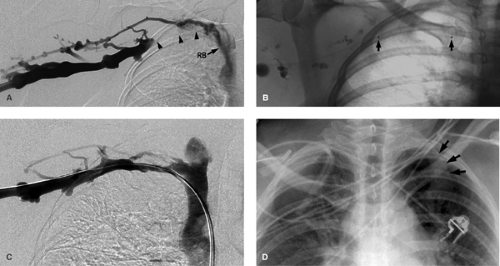
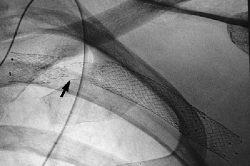
In Paget-Schrötter syndrome (Figs. 14-11 and 14-12) the aims of management are to perform thrombolysis to restore a lumen and remove the DVT as a prelude to the definitive treatment, which is surgical decompression of the vein. Stent placement is not recommended primarily, as the extrinsic compression can pinch off the stent, compressing and possibly fracturing it Fig. 14-13. Once the patient has had decompressive surgery and recurrent symptoms or stenosis develop, then angioplasty or stent placement can be done.
Patients with arteriovenous fistula (AVF) have high flows through these veins, which helps keep the treated segment of vein patent. In the absence of an AVF, stent placement overall does not provide durable patency rates because of the relatively low flows in these veins. However, in patients with a limited prognosis such as from malignancy, palliative stenting should be performed.
If PE from upper-extremity thrombus is a concern, and a SVC filter is needed, plan to use an optional filter (see the later section).
Axillary-subclavian Thrombolysis
The preferred access by the authors is the ipsilateral arm venous system, the other choices being the femoral vein or the contralateral internal jugular vein or upper-extremity veins. If DVT extends into the axillary and upper arm veins, plan to access a patent segment of brachial or basilic vein as this will allow the entire thrombosed segment to be treated and restore inflow into the axillary-subclavian vein. Perform an upper-extremity venogram. Using this as a road map, a hydrophilic-coated guidewire should cross the acute DVT relatively effortlessly. Once the thrombus is crossed, a single infusion catheter with infusion side holes of appropriate length is positioned to treat the entire thrombosed segment of vein. Confirm appropriate position with a venogram through the infusion system.
Pulse-spray intrathrombotic lacing can be performed prior to thrombolytic infusion. As the clot responds to treatment, a shorter infusion length should be used to treat just the diseased segment of vein. During follow-up venograms, mechanical thrombectomy can be tried (see the section on venous thrombolysis). Once clinical improvement is achieved along with improved venographic appearance (restoration of flow within the axillary-subclavian vein), thrombolysis is stopped and plans made to address the underlying etiology definitely.
Pulse-spray intrathrombotic lacing can be performed prior to thrombolytic infusion. As the clot responds to treatment, a shorter infusion length should be used to treat just the diseased segment of vein. During follow-up venograms, mechanical thrombectomy can be tried (see the section on venous thrombolysis). Once clinical improvement is achieved along with improved venographic appearance (restoration of flow within the axillary-subclavian vein), thrombolysis is stopped and plans made to address the underlying etiology definitely.
Axillary-subclavian Stent Placement
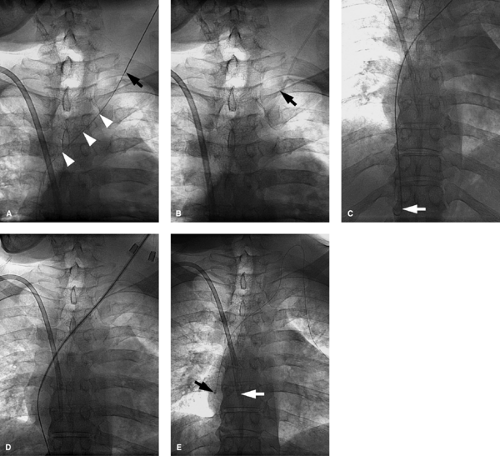
Stent diameters required typically range from 7 to 14 mm. Because of the small size of the arm veins, arm access is not used if sheaths >7F in size are going to be utilized. The authors prefer to access the femoral vein in such cases and advance the needed tools into the axillary-subclavian veins from this location. Make sure that not only the sheath but also the stent delivery system is of adequate length to reach the diseased segment of vein. If this is not possible, then evaluate an ipsilateral or contralateral internal jugular vein approach Fig. 14-14. This is not ideal, as one has to negotiate some sharp curves from the jugular into the subclavian vein. Similar technical considerations apply even if one is performing angioplasty alone. The steps otherwise are discussed in the section on venous access. If stent placement is going to cover the internal jugular vein orifice, the authors prefer to use a Cook Z-stent (Cook Inc., Bloomington, IN) as the large interstices can allow for catheter placement through the stent Fig. 14-7 via the internal jugular vein route and so preserve this option for venous access. This requires larger sheaths, and the femoral vein approach will be needed. If the lesion is already crossed via an arm access, the access can be converted to a femoral route as described in the section on SVC stent placement Fig. 14-15. This obviates the need to cross the lesion twice, and the arm access can be used to perform road-mapping venograms.
In stenosis caused by benign etiology such as previous central venous catheters, angioplasty should be tried.13 If there is recoil of >50%, this suggests a tendency of the stenosis to recur and thrombose. In the absence of high flows (such as in patients having hemodialysis fistulas), stents will also tend to thrombose. Stent placement should only be done after repeated failure of angioplasty or if there is significant elastic recoil, as discussed earlier.
