Ultrafiltration and Dialysis
Robin G. Sutton
David M. Rothenberg
Patients undergoing cardiopulmonary bypass (CPB) often develop fluid overload and electrolyte imbalances (1,2,3). In addition, exposure to foreign surfaces of the extracorporeal circuit and surgical trauma can itself promote capillary permeability and shifting of fluid to the extravascular space (1,2,3). Ultrafiltration and dialysis can help attenuate these changes and are therefore important adjuncts to CPB and related extracorporeal technologies. Ultrafiltration and dialysis are both utilized to manage blood volume, hemoglobin, protein, and certain electrolyte concentrations (2,4). In addition, several studies suggest that ultrafiltration and dialysis may reduce mediators that initiate a systemic inflammatory response syndrome (SIRS) (5,6,7).
Ultrafiltration is the movement of water across a membrane as the result of a hydrostatic pressure gradient or transmembrane pressure (TMP) (8). No dialysate on the opposite side of the membrane is required. As water diffuses, it creates a solute concentration gradient across the membrane. These solutes then diffuse across the membrane, equalizing the concentrations in a process of solute removal called convection. The fluid removed during ultrafiltration is called ultrafiltrate or plasma water.
Dialysis refers to a process in which the blood is separated from a crystalloid solution or dialysate by a semipermeable membrane (9). A solute concentration gradient exists between the blood and the dialysate, resulting in solute transport by diffusion from a higher to a lower concentration. Ultrafiltration may be employed during dialysis by altering the TMP (10).
The purpose of this chapter is to describe the theory of ultrafiltration and dialysis and explain their various uses and benefits in the extracorporeal circuit during CPB.
HISTORY OF DIALYSIS AND ULTRAFILTRATION
In 1854, Thomas Graham, a Scottish chemist, presented a paper entitled “Osmotic Force,” which described the process of separating substances using a semipermeable membrane (11). He later demonstrated that treated parchment paper could be used to separate larger molecules or colloids from crystalloids. He was also the first to describe the direct relation between solute molecular weight and solute diffusion rate. After Graham’s paper was published, other investigators continued to study various membrane materials that might be used to separate colloids from crystalloids. In 1855, Adolf Fick described the use of collodion, a cellulose-trinitrate derivative, as a diffusive membrane (12).
In 1913, John Jacob Abel’s interest in deriving usable solutes from animal blood led to the first reported dialysis procedure (13). Abel used a collodion membrane and, because blood was circulated outside the animal, it was necessary for Abel to find a way to keep the blood from clotting when exposed to foreign surfaces. Abel solved this problem by creating hirudin, an anticoagulant derived from crushed leech heads.
The first clinical dialysis procedure was performed by George Haas in 1924 (9). Between 1924 and 1928 he dialyzed six patients, but unfortunately had no survivals. However, Haas made significant progress in the field of hemodialysis in 1927 by the addition of a blood pump and use of a newly discovered anticoagulant, heparin.
Throughout the 1930s, many investigators developed and studied various semipermeable membrane materials, including cellophane and chemically modified cellulose (14,15). After World War II, Willem Kolff, at the University of Groningen in the Netherlands, built an artificial kidney employing the regenerated cellulose membrane, cellophane. This device was a rotating drum barrel made of slats, with open spaces between the slats. The membrane material used was a relatively new material originally developed for food packaging. The cellophane sausage casing was wound around the drum. The drum was rotated by an electric motor and submerged in a tank filled with dialysate solution. The blood was drawn from the patient into the cellophane casing by gravity (Fig. 4.1). Between 1943 and 1944, Kolff dialyzed a total of 15 patients; however, only one survived. In 1945, he dialyzed a comatose patient in acute renal failure for 1 week. Her renal function returned and she eventually recovered to be released from the hospital (16). Kolff’s book, “New Ways of Treating Uremia” (17) became the first manual for treating patients on hemodialysis, and following World War II he collaborated with colleagues at Brigham Hospital to make significant improvements to his original device, which became known as the Kolff-Brigham kidney. Between 1954 and 1962, he shipped his dialysis machines to 22 centers worldwide. This dialysis machine
was copied by others and by the mid-1940s there were many dialysis programs throughout the world. In 1950, Kolff collaborated with Drs. Victor Vertes and Bruno Watschinger to improve a previously described coil-type dialyzer in which cellulose acetate tubing was wrapped around a plastic core. He developed the first ready-to-use disposable artificial kidney by placing the devices in polyethylene bags for sterilization (18).
was copied by others and by the mid-1940s there were many dialysis programs throughout the world. In 1950, Kolff collaborated with Drs. Victor Vertes and Bruno Watschinger to improve a previously described coil-type dialyzer in which cellulose acetate tubing was wrapped around a plastic core. He developed the first ready-to-use disposable artificial kidney by placing the devices in polyethylene bags for sterilization (18).
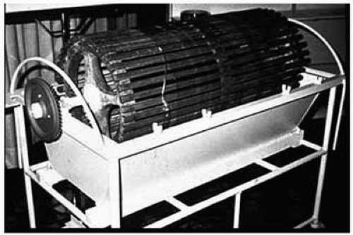 FIGURE 4.1. Rotating drum kidney designed by Willen Kolff in the 1940s. |
The development of the flat or parallel plate dialyzer began in 1947 by Leonard Skeggs and Jack Leonards (19). In this design, sheets of membrane material were sandwiched between two rubber pads and incorporated multiple membrane layers to reduce the blood volume and increase the membrane surface area. By the early 1950s, Kiil reported results with a flat plate dialyzer in which blood was made to flow between two sheets of cellophane supported by solid mats with grooves for the circulation of dialysate.(20) In 1956, Richard Stewart began the development of the hollow fiber dialyzer design (21). It was made from a modified cellulose material, cellulose diacetate, and provided a high-efficacy solute transport while maintaining a low priming volume and a low resistance to blood flow. The membrane material, extruded in hollow fibers, was cut and bundled together, then potted in polyurethane on each end and encased in a polycarbonate shell. Blood flowed through the hollow fiber and the dialysate flowed around the hollow fibers. This model became commercially available in 1970 and is the type of dialyzer and ultrafiltrator most widely used currently.
ULTRAFILTRATION (HEMOCONCENTRATION)
Ultrafiltration is achieved through the filtration of water across a semipermeable membrane using the energy derived from a hydrostatic pressure gradient (11). When water crosses the membrane, it creates a solute concentration gradient between the blood and the ultrafiltrate side of the membrane, which has no solutes. The dissolved solutes, which have a higher concentration in the blood, follow the concentration gradient and are transferred from the blood to the ultrafiltrate, the so-called solute drag or convection. This process of removing plasma water or ultrafiltrate from the blood utilizes a microporous membrane material commonly manufactured in a hollow fiber configuration.
Mechanism of Action
Consider a tank separated by a semipermeable membrane. A semipermeable membrane implies that certain substances will penetrate the membrane while others will not. This relates to microscopic holes in the membrane, which only allow water and small molecular weight solutes to pass. If one side of the tank is filled with blood and a pressure is exerted on that compartment, water from the blood will move across the membrane into the other compartment. Because of their higher concentration in the blood compartment, the solutes with small molecular weight will move to the water side of the compartment until there is an equal concentration on both sides. This results in a concentration of blood cells and large molecules on one side of the membrane and water and small molecules on the other side (Fig. 4.2).
During ultrafiltration, the blood passes through a bundle of hollow fibers made from a microporous membrane. The hollow fibers are between 180 and 200 µm in diameter and the pores of the microporous membrane are between 5 and 10 nm (22,23). Thousands of hollow fibers are configured in a bundle and encased in a polycarbonate shell (Fig. 4.3). As blood flows through the hollow fibers of an ultrafiltrator, also called a hemoconcentrator, it creates a positive pressure within the hollow fibers. This pressure differential between the blood side and the atmospheric pressure on the ultrafiltrate side of the membrane drives water across the membrane. As in the tank analogy, water is shifted from the blood path to the ultrafiltrate compartment; a solute concentration gradient is generated between the blood and the ultrafiltrate. By convection, solutes smaller than the membrane pore size move with the water to equalize the solute concentration gradient. In many ways the process mimics glomerular filtration (Table 4.1).
The pressure gradient between the blood path and the ultrafiltrate compartment is called the transmembrane pressure. The TMP can be expressed by the formula
TMP = (Pin + Pout)/2 + V
where Pin = Blood inlet pressure, Pout = Blood outlet pressure, and V = Negative pressure applied to the effluent side of the hemoconcentrator.
To avoid membrane rupture, the TMP must not exceed the manufacturer’s recommended pressures of 500 to 600 mm Hg. The rate of fluid removal depends on the membrane permeability, blood flow, TMP, and hematocrit (22). The membrane permeability is related to the pore size, membrane material, and membrane thickness, and is described by the ultrafiltration coefficient (KUF) (22,24,25). The KUF relates the rate of water removal to the TMP for a particular device at a constant
blood flow. Typical rates are between 2 and 50 mL/hr/mm Hg. As the KUF units imply, increase in the TMP increases the rate of water removal. The KUF is also dependent on the blood flow through the ultrafiltrator, with higher blood flow resulting in a higher KUF (Fig. 4.4). Just as lower hematocrit levels and lower plasma protein concentrations will increase glomerular filtration rate, they will also increase the ultrafiltration rate.
blood flow. Typical rates are between 2 and 50 mL/hr/mm Hg. As the KUF units imply, increase in the TMP increases the rate of water removal. The KUF is also dependent on the blood flow through the ultrafiltrator, with higher blood flow resulting in a higher KUF (Fig. 4.4). Just as lower hematocrit levels and lower plasma protein concentrations will increase glomerular filtration rate, they will also increase the ultrafiltration rate.
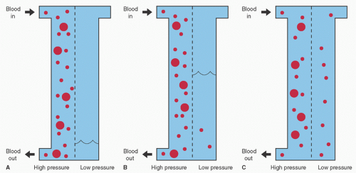 FIGURE 4.2. Convection. A: Blood compartment is pressurized and water from the blood moves across the membrane. B: Results in blood on one side of the membrane and water on the other side, which creates a solute concentration gradient between the two components. C: Small molecular weight solutes diffuse across the membrane to equalize the concentration gradient. |
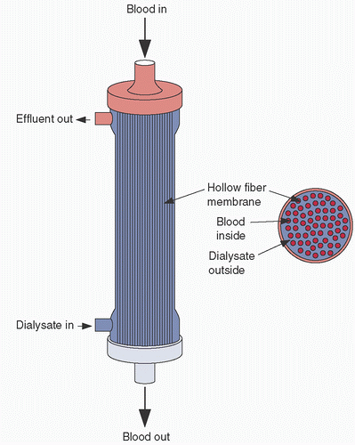 FIGURE 4.3. Hollow fiber hemoconcentrator. |
TABLE 4.1. Dialyzer-nephron comparison | ||||||||||||
|---|---|---|---|---|---|---|---|---|---|---|---|---|
|
Because the process of ultrafiltration removes plasma water and diffusible solutes in equal concentration to the plasma water, the overall concentration of the diffusible solutes are not affected. Although dependent on the membrane material and pore size, typically, solutes greater than 65,000 Da are not removed by ultrafiltration. Cellular elements, plasma proteins,
and protein-bound solutes will not be removed and will therefore be concentrated (26).
and protein-bound solutes will not be removed and will therefore be concentrated (26).
 FIGURE 4.4. Transmembrane pressure (TMP) versus ultrafiltration rate (KUF) for a typical hemoconcentrator. To maximize KUF, both the blood flow (Q) and the TMP must be adjusted. |
Sieving Coefficient
The ability of a solute to be filtered through the ultrafiltrator membrane depends on the molecular weight of the solute compared with the membrane pore size, the proportion of the solute that is protein bound, and the surface charge of the solute (27). The sieving coefficient is the ratio of ultrafiltrate solute concentration to plasma solute concentration and ranges from 0 to 1.0. A sieving coefficient of 1.0 indicates that the ultrafiltrate solute concentration and the plasma solute concentration are equal and that the solute passes freely across the membrane. A sieving coefficient of 0 indicates that none of the solute passes through the membrane. Small molecular weight solutes that are not protein bound are easily removed by ultrafiltration and have a sieving coefficient of 1.0. In the case of partially protein-bound small molecular weight solutes, the ultrafiltrate solute concentration will be equal to the non-protein-bound solute concentration.
Indications and Outcomes
The use of ultrafiltration during CPB was first reported in 1979 by Darup et al. (4). In the early 1980s, several other investigators reported utilizing ultrafiltration in the extracorporeal circuit and found that removing plasma water during CPB resulted in improvement in a number of aspects of patient care (28,29,30,31,32).
Patients undergoing CPB are subject to significant hemodilution, primarily due to the extracorporeal circuit prime of 1 to 2 L of crystalloid solution, with homologous blood products and plasma proteins rarely added to the extracorporeal circuit prime to minimize bank blood usage (33). During CPB, excess crystalloid may accumulate in the venous reservoir through cardioplegia and surgical irrigation from cardiotomy suction. Patients undergoing CPB for heart surgery may have increased blood volumes due to congestive heart failure and/or renal failure (34). Ultrafiltration may remove excess fluid; however, the amount of fluid removed is limited by the minimal level allowed in the venous reservoir of the extracorporeal circuit. Once the minimum reservoir volume has been achieved, further increases in hematocrit and plasma protein levels may only be accomplished by the addition of homologous red blood cells or albumin. After the addition of the red cells or albumin, ultrafiltration may continue until the volume equal to the added red cells or albumin is removed (Fig. 4.5).
The extracorporeal circuit also exposes the patient’s blood to foreign surfaces that may trigger SIRS and, in particular, increase capillary permeability (35). Therefore, as CPB is initiated, the patient is subject to a dilutional decline in hemoglobin and serum protein concentrations and contact activated inflammatory capillary leak, leading to fluid movement to the interstitial space, tissue edema, and decreased end-organ perfusion.
Ultrafiltration can concentrate the blood without the removal of plasma proteins, can be utilized during CPB when there is excess reservoir volume, and is particularly useful when the patient is resistant to diuretics (28,29). Studies have shown that patients who undergo ultrafiltration demonstrate increased protein and red blood cell concentrations (28,36) and decreased lung waters (29), reduced fluid balance (29), and reduced tissue edema (37,38,39). It has also been found to improve perioperative hemostasis and reduce postoperative ventilatory support (4).
Technical Applications
The hemoconcentrator or ultrafiltrator is configured in parallel to the extracorporeal circuit. Blood may be propelled through a pump (28,40), but for simplicity, it is generally configured in the extracorporeal circuit as a passive shunt from a point of higher pressure to lower pressure. In the pumpless configuration, the inflow to the ultrafiltrator originates from a port or connection off the high-pressure arterial line (distal to the arterial pump) and the outflow of the ultrafiltrator returns to a lower pressure port or connection located either on the venous line or the venous reservoir (Fig. 4.6). Without the pump, the flow through the ultrafiltrator is dependent on the pressure differential between the inflow and outflow of the ultrafiltrator. This can be easily approximated in the adult patient by using the principles of flow and resistance. During CPB, the perfusionist monitors line pressure distal to the arterial pump, which ranges between 150 and 250 mm Hg, and is dependent on blood-flow rate and resistance. The resistance to flow is determined by arterial cannula size, design, and placement, as well as the patient’s arterial blood pressure. If the ultrafiltrator shunt, which is parallel to the main circuit, is opened and the pump flow and other resistance-related variables remain the same, blood flow to the patient through the arterial cannula will decline and the line pressure will drop due to diminished resistance to blood flow. If the arterial pump flow is increased
to the point where line pressure returns to baseline, then, theoretically, flow to the patient should also return to baseline. The difference between old pump flow and new pump flow is the flow shunted to the hemoconcentrator (Fig. 4.7). A clamp on the ultrafiltrator blood outflow line will reduce shunting, but it will not increase pressure inside the hollow fibers nor will it increase TMP or ultrafiltration rate. It will, in fact, reduce ultrafiltration rate because blood flow through the ultrafiltrator has been reduced. A flowmeter may be used for more precise measurements and is highly recommended
in pediatric patients (41). When using a centrifugal pump, the flow probe should be distal to the ultrafiltrator shunt to determine the actual blood flow to the patient and not the combined blood flow to the patient and ultrafiltrator.
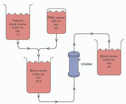 FIGURE 4.5. Ultrafiltration can maximize the effect of homologous red blood cell administration. PRBC, packed red blood cells; Hct, hematocrit. |
 FIGURE 4.6. The hemoconcentrator is configured as a passive shunt parallel to the cardiopulmonary bypass (CPB) circuit. |
 FIGURE 4.7. Example of blood flow through a hemoconcentrator setup as a passive shunt from the arterial line that shunts blood away from the patient. This shunt varies and is based on the arterial line pressure. A: Hemoconcentrator shunt is closed. The pump blood flow is 5 L/min, which is delivered to the patient through the arterial line requiring a line pressure of 150 mm Hg. B: Hemoconcentrator shunt is opened. If the pump flow remains at 5 L/min the line pressure will drop; however, the distribution of blood flow through the hemoconcentrator and to the patient is unknown. C: If the pump flow is increased such that the line pressure returns to baseline, then it can be assumed that the blood flow to the patient has returned to 5 L/min and that the blood flow through the hemoconcentrator is the difference between the old pump flow and the new pump flow (in this case 0.25 L/min). |
Tubing from the effluent side of the ultrafiltrator is attached to a collection canister and, given that ultrafiltrators used for CPB have relatively high ultrafiltration rates (also termed high flux), sufficient rates of fluid removal are achieved by establishing a hydrostatic pressure gradient by altering the height between the ultrafiltrator and the canister. The hydrostatic gradient can vary between 60 and 90 cm, resulting in an effective hydrostatic pressure of approximately 45 to 65 mm Hg. The TMP may be augmented by applying a vacuum source to the effluent side of the ultrafiltrator.
The process of ultrafiltration may potentially lead to hypovolemia, with increased osmolarity in the intravascular volume causing interstitial fluid to slowly shift into the vascular space (30). A patient supported on CPB can tolerate a higher rate of ultrafiltration without becoming hemodynamically unstable because the cardiac output is controlled by the bypass pump and does not depend on the intravascular volume.
ZERO-BALANCED ULTRAFILTRATION (Z-BUF)
The primary purpose of ultrafiltration during CPB is to remove excess water and to concentrate the cellular elements and proteins in the blood. Electrolytes and other solutes are also removed but in equal concentration to the patient’s plasma water. Therefore, the patient’s plasma concentration of diffusible solutes remains unchanged. As mentioned previously, investigators studying ultrafiltration during and immediately after CPB found improvements in patient hemodynamics, cardiac contractility, and oxygenation. Originally these benefits were attributed to water removal; however, subsequent investigations testing for various substances in the ultrafiltrate found measurable levels of cytokines (42,43,44,45,46). Because most cytokine and complement levels reach their peak during rewarming, Journois et al. (47) hypothesized that continuous ultrafiltration during this period would further attenuate the inflammatory response. To allow continuous ultrafiltration during the rewarming phase of CPB, the authors replaced the ultrafiltrate with a balanced electrolyte solution. They matched the ultrafiltration rate with the infusion rate by loading the ultrafiltration effluent line and the electrolyte solution infusion tubing into a single roller pump. The effluent and infusion tubing were loaded in opposite directions so that the ultrafiltration rate was equal to the infusion rate and the patient remained isovolemic. When comparing patients who received Z-BUF during rewarming to a control group that did not receive ultrafiltration during CPB, an improvement was noted in postoperative alveolar-arterial oxygen gradient that significantly correlated with the volume of ultrafiltrate removed in the Z-BUF group. The treatment group also had less blood loss and a lower body temperature in the intensive care, further supporting the theory that the inflammation process had been attenuated. Z-BUF is similar to hemofiltration utilized in dialysis units, whereby plasma water is ultrafiltrated at a high rate with the volume removed replaced with a balanced electrolyte solution (48,49).
A form of Z-BUF has also been used by perfusionists to correct hyperkalemia (49,50). Potassium loads during cardiopulmonary bypass originate from potassium-based cardioplegia and homologous red blood cells and may exceed the patient’s ability to clear excess potassium through normal glomerular filtration (51,52,53). As the patient’s blood volume is reduced by ultrafiltration, the potassium level is not affected because the ultrafiltrate potassium levels will always be in equal concentration to the plasma. When ultrafiltration is continuous, the potassium levels can be lowered by replacing the volume with a solution low in potassium.
Z-BUF has also been used to correct severe electrolyte and acid-base disturbances in adults undergoing cardiac surgery.
Electrolyte and acid-base corrections can be accomplished rapidly, and because the clinician can select the concentration of diffusible solutes in the replacement fluid, they can more accurately predict treatment effects (54,55).
Electrolyte and acid-base corrections can be accomplished rapidly, and because the clinician can select the concentration of diffusible solutes in the replacement fluid, they can more accurately predict treatment effects (54,55).
Circuitry and Management of Z-BUF
In Z-BUF, the hemoconcentrator is positioned in the CPB circuit and plasma water is removed similar to ultrafiltration. However, in Z-BUF, the volume of plasma water removed is replaced by an equal amount of a balanced electrolyte solution.
When the purpose of Z-BUF is to remove inflammatory mediators, the replacement fluid can be commercially manufactured solutions such as Hartman solution, lactated Ringers, Plasma-Lyte-A, or Normosol. These replacement solutions contain acetate or lactate, both of which undergo conversion to bicarbonate in the liver and muscle and provide the necessary buffer to offset the bicarbonate loss during Z-BUF. Bicarbonate-containing solutions are themselves unstable and can form precipitates when mixed with solutions containing calcium or magnesium. When using Z-BUF to reduce potassium levels, the previously mentioned replacement solutions do not efficiently dilute potassium levels because they all contain more than 4 mEq/L of potassium. It is a challenge to find an easily available, cost-effective, balanced electrolyte solution low in potassium, and therefore 0.9% sodium chloride is often used. Because 0.9% sodium chloride does not contain bicarbonate, it must be replaced in the form of sodium bicarbonate. If Z-BUF with 0.9% sodium chloride is used in excess, the patient can develop hypernatremia due to the high sodium content of 0.9% sodium chloride (154 mEq/L). If 20 mEq of sodium bicarbonate is added to each liter of 0.9% sodium chloride to replace the lost bicarbonate, each liter will contain 174 mEq of sodium. In the event that these solutions are given, the clinician must be sure to monitor sodium levels to avoid hypernatremia. In addition, because many patients are on preoperative diuretics, they present to the operating room with low sodium levels. If the sodium levels are normalized quickly (>2 mEq/L/hr), patients may be at risk for central pontine myelinolysis, which is characterized by focal demyelination in the pons and extrapontine areas of the brain (56). Z-BUF with 0.9% sodium chloride also depletes magnesium and calcium and can elevate chloride, resulting in hyperchloremic metabolic acidosis (57


Stay updated, free articles. Join our Telegram channel
Full access? Get Clinical Tree
