Pacemaker Troubleshooting
Pacemaker diagnostics and automaticity have become increasingly more sophisticated. Knowledge of the device capabilities and the clinical situation of the patient is key to successful troubleshooting. Whether a patient has a clinical episode that suggests system malfunction or is having routine follow-up, device evaluation should be performed in an orderly fashion so that potential malfunction is not overlooked. Some instances of device “malfunction” are not malfunctions at all, but rather are the result of an inappropriately programmed device functioning as programmed or unrecognized appropriate function, i.e., pseudo-malfunction. In some instances, early component failure is intermittent, and even meticulous evaluation of the system may not initially reveal a problem.
Successful troubleshooting requires a systematic approach (Table 10.1). Noninvasive evaluation should be exhausted first and involve careful evaluation of any symptoms; the pacing indication; available electrocardiographic tracings; the function and radiographic appearance of the lead system; and stored information obtained by telemetry from the pulse generator. Noninvasive diagnosis and correction of any malfunction are always preferable to operative management. Before invasive troubleshooting, one should take advantage of every possible source of assistance, including careful review of the technical manual and contacting the manufacturer for help. If noninvasive evaluation is unrewarding, operative assessment may be necessary.
Table 10.1 Troubleshooting steps.
| Clinical assessment |
| Indication for pacing |
| Focused history and physical examination |
| Review of operative report |
| Electrocardiography |
| Rate |
| Pacing and sensing |
| QRS axis |
| Magnet response |
| Chest radiograph |
| Device type and location |
| Proper contact between lead pins and setscrews |
| Lead integrity |
| Lead position |
| Pacemaker interrogation |
| Sensing threshold(s) |
| Pacing threshold(s) |
| Lead impedance |
| Battery status |
| Special features |
| Histograms |
| Trend data |
| Counters |
| Programming |
| Review technical manual for other “clues” to perceived malfunction |
| Contact the manufacturer for assistance |
| Operative assessment |
| Appearance of pocket |
| Assessment of lead connection(s) |
| Visual inspection of lead(s) |
| Electrical assessment of lead(s) |
| Patency of venous system |
In order to adopt a systematic approach to troubleshooting, an understanding of the common problems encountered in a device clinic and their causes is necessary.
The most common problems encountered in pacemaker management include:
- Failure to sense
- Failure to capture
- Failure to output
- Change in magnet rate
- Recurrent preimplant symptoms
- Palpitations/tachyarrhythmias
- Hemodynamic compromise
- Device advisory or recall.
Clinical Assessment
Knowing the patient and taking a careful history are very important in evaluating any pacing system, especially if malfunction is suspected. Clinical assessment should include the following information: the original indication for pacing, whether or not the patient is pacemaker-dependent, activity immediately preceding the clinical event, symptoms experienced by the patient during the event, observations made by witnesses, and duration of the event. Symptoms of pacing system malfunction may be subtle and include fatigue, weakness, confusion, neck pulsations, or activity intolerance. Some types of pacing system malfunctions may occur totally without symptoms. For example, intermittent failure to capture in the nonpacemaker-dependent patient or undersensing may not be associated with any symptoms and may be discovered only at the time of routine evaluation. During routine follow-up, the patient should be asked about symptoms potentially related to pacemaker complications, such as recurrence of preimplant symptoms, syncope, near-syncope, palpitations, and any perception of a slow, fast, or irregular pulse. It is important to obtain information from the operative report if possible, including device model, lead models, acute intraoperative pacing and sensing thresholds, and impedance values, and any difficulties encountered during implantation.
Many devices store information on lead models, acute threshold data, clinical information (e.g., medication regimen), name of institution where the device was implanted, and name of the implanting physician in their memory, for retrieval upon interrogation. All manufacturers have toll-free numbers that may be used to obtain implant information (generally kept by the manufacturer of the pulse generator), such as device model and lead models (Table 10.2). The manufacturers can also provide technical information about device and lead performance and assist with electrocardiographic interpretation and troubleshooting. (If calling for implant information ask for “patient registration” and if calling for troubleshooting assistance ask for “brady technical support”.)
Table 10.2 Toll-free, 24-h telephone numbers of manufacturers.*
| Biotronik | 1-800-547-0394 |
| Boston Scientific | 1-800-CARDIAC |
| Sorin/ELA | 1-800-352-6466 |
| Medtronic | 1-800-328-2518 |
| St. Jude Medical | 1-800-722-3774 |
*As of January 2012.
It is also very useful (but sometimes difficult) to obtain the chest radiograph taken immediately after implantation for comparison with current radiographs (see Chapter 11: Radiography of Implantable Devices).
Identifying the Pulse Generator
The first step in troubleshooting is pacemaker interrogation. However, interrogation requires knowing the pulse generator manufacturer, because pulse generators only communicate with programmers made by the same manufacturer. Methods to identify the manufacturer include review of the pacing system identification card that all patients should carry, review of medical records that identify the pacemaker manufacturer, or radiographic identification.
With a high-quality posteroanterior chest X-ray, it may be possible to see a radiographic code that will identify the manufacturer (Chapter 11, Fig. 11.3). Alternatively, interrogation with available programmers can be attempted. No adverse consequences should occur from attempting to interrogate the device with a noncompatible programmer. In the event that interrogation by multiple programmers is unsuccessful or not possible, i.e., programmers from multiple manufacturers not available, calls can be made to “patient registration” for each of the device manufacturers. You will need to provide the patient’s name and possibly the date of birth. If the manufacturer’s products were implanted and appropriately registered, the information should be on record. If the appropriate programmer is not immediately available, the company should be contacted at the number given in Table 10.2 and assistance requested.
Electrocardiographic interpretation and troubleshooting is made significantly easier once the pulse generator is identified, programmer acquired, and interrogation completed.
Electrocardiographic Interpretation
If presented with a paced electrocardiogram and no other information, it is reasonable to approach interpretation with several specific questions:
- Is pacing occurring in the atrium, the ventricle, or both?
- Is sensing occurring in the atrium, the ventricle, or both?
- Based on the first two questions, is it possible to identify the pacing mode or at least narrow the possible options?
- What are the lower and (if applicable) upper rate limits?
- What other measurable intervals are present? For example, what is the atrioventricular (AV) interval; more specifically, what are the AV, PV, or AR intervals?
- Is there any evidence that the programmed rate, if identifiable, has been violated?
- On the electrocardiographic tracing available is there evidence of normal sensing and capture?
Only after extracting as much information regarding what is believed to be “normal” operation should attention be turned to any possible abnormality.
Lead Integrity
The lead system is the most vulnerable component of the pacing system and the most frequent site of system failure other than expected battery failure (depletion). Lead technology continues to improve, and many manufacturers now have lead performance data that can be accessed through their published product performance reports.
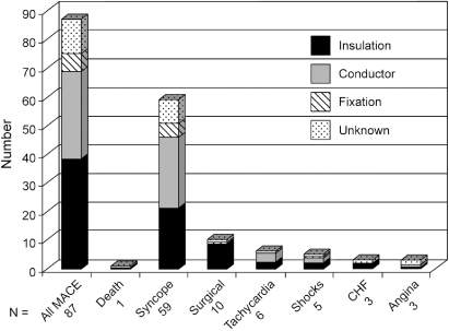
Insight regarding etiology of transvenous lead failure, presenting signs of failure, and time distribution of failure can be gained from data from a multicenter registry of recognized lead and pulse generator problems.1 It should be emphasized that this registry includes only leads and pulse generators that have been removed from service; it is not a prospective registry of all implants. Insulation defects are the most common cause of failure, followed by conductor and fixation failure, although there is variability depending on lead construction. From registry data, when the distribution of lead failure by number of years in service was analyzed, the median time to failure for all leads was 7.2 ± 5.2 years, with a “failure” peak in the first year followed by a second peak at approximately year 9. The adverse clinical events (most commonly syncope) and their relationship to the mechanism of failure are shown in Fig. 10.1.
Fig. 10.1 Major adverse clinical events (MACE); and their relationship to the causes of; transvenous lead failure.
(From Hauser RG, Hayes DL, Kallinen LM, et al. Clinical experience with pacemaker pulse generators and transvenous leads: an 8-year prospective multicenter study. Heart Rhythm 2007; 4:154–60, by permission of Elsevier.)
If there is concern or evidence of lead failure, it may be helpful to look at product performance data available from the manufacturer. Most manufacturers make product performance information available on a regular basis. Another valuable source, albeit somewhat to difficult to navigate, is the Food and Drug Administration (FDA) website, specifically the MAUDE database (http://www.accessdata.fda.gov/scripts/cdrh/cfdocs/cfMAUDE/search.cfm).
The chest radiograph is a valuable component in lead evaluation (see Chapter 11: Radiography of Implantable Devices). The lead should be inspected in its entirety, from the contact of the pin with the setscrew to the position of the lead within its cardiac chamber. Unfortunately, deterioration of the lead insulation is rarely visible on the chest radiograph, and fractures of the coil are not always obvious. A frequent site of lead damage if a subclavian implant approach has been utilized is the region between the first rib and the clavicle; this site should be carefully inspected for coil fracture (subclavian crush syndrome). The risk of subclavian crush becomes higher if multiple leads are in place. If an older chest radiograph is available for comparison, the presence of gross lead dislodgment can be determined. This presentation is becoming less common because subclavian approach is now less frequently used.
Abandoned leads in contact with the electrode of an active lead may cause an artifact, which can be interpreted by the pacemaker as a cardiac event and cause inappropriate inhibition. Although findings on the chest radiograph suggestive of lead fracture, dislodgment, or poor connection between the lead pin and generator setscrew are helpful in identifying lead problems, absence of such findings does not exclude lead failure. (For detailed information on the radiographic appearance of pacing systems, see Chapter 11: Radiography of Implantable Devices)
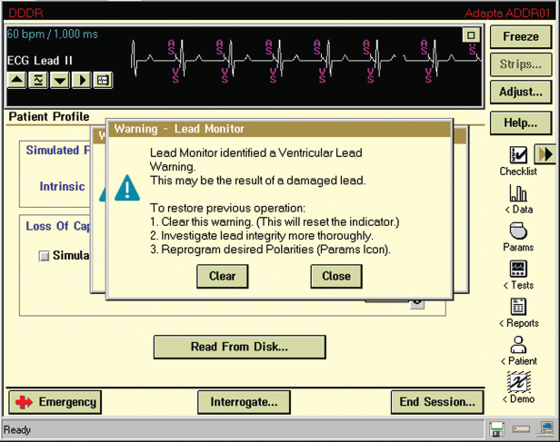
Lead evaluation should also include the measured lead impedance. For currently available leads, an impedance >2000 Ω indicates a conductor fracture or loose setscrew, and low impedance (<200 Ω indicates an insulation defect. (Note: expected impedance is a function of lead design, so that for some leads values >1500 Ω are abnormal. A call to the manufacturer is helpful in determining an acceptable impedance range for a given lead model.) Most contemporary pacemakers periodically measure and store impedance values, and creates plots or tables summarizing periodic values, facilitating detection of changes in lead function (Fig. 10.2). Even if a measured value is within the “normal” range for that particular lead, a notable change in impedance from previous values should raise suspicion. Most pulse generators have the ability to respond to a sudden change in impedance by automatically reprogramming the pacemaker from bipolar to unipolar pacing and sensing configuration (Fig. 10.3).
Fig. 10.2 Telemetry printout noting atrial and ventricular; lead impedances but also a “trend” of impedance; values for both leads. In this example the trend displays information for approximately 11 months and impedance values are stable for both leads.
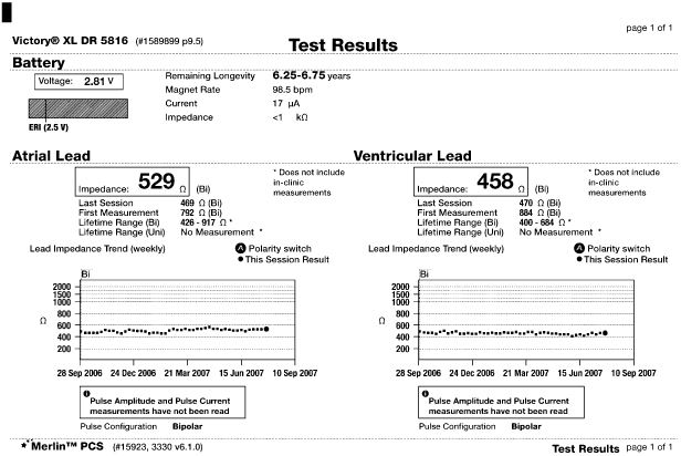
Fig. 10.3 A programmer “screen” with a warning that the lead monitor identified a ventricular lead warning. Such a warning may be a sudden change in lead impedance resulting in automatic switch from bipolar to unipolar pacing configuration.
Pulse Generators
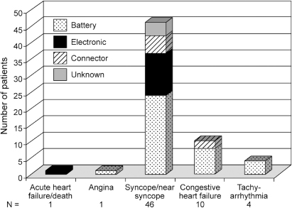
Multicenter registry data provide insight into pulse generator failure mechanisms and associated adverse clinical events. The single most common reason for pulse generator removal from service was expected battery depletion, accounting for 92% of removals. Other reasons included medical advisory or recall (4%), electronic failure (2%), connector failure (1%), and unknown cause of failure (1%).1 The impact of rate responsiveness on observed battery longevity is shown in Fig. 10.4. Figure 10.5 demonstrates major adverse clinical events and their relationship to pulse generator removal.
Fig. 10.4 Observed pulse generator battery longevity assessed by those with vs. those without the capability of rate-responsiveness. The percentages along the abscissa represent the proportion of pulse generators that failed in ≤3 years, the definition of premature battery failure in this registry.
(From Hauser RG, Hayes DL, Kallinen LM, et al. Clinical experience with pacemaker pulse generators and transvenous leads: an 8-year prospective multicenter study. Heart Rhythm 2007; 4:154–60, by permission of Elsevier.)
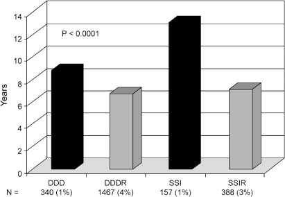
Fig. 10.5 Major adverse clinical events and their relationship to the causes of pulse generator failure.
(From Hauser RG, Hayes DL, Kallinen LM, et al. Clinical experience with pacemaker pulse generators and transvenous leads: an 8-year prospective multicenter study. Heart Rhythm 2007; 4:154–60, by permission of Elsevier.)
Clinical Troubleshooting
The number of programmable features available in pacemakers continues to increase. Although these options permit individualizing optimal pacing therapy for patients, they can make troubleshooting a complex endeavor. A detailed understanding of the correct function of these devices is necessary to provide comprehensive evaluation; technical manuals and expert representatives from the manufacturer provide important assistance.
Pacing and Sensing Threshold Evaluation
An initial step in troubleshooting is to determine the patient’s native rhythm. This may require turning down the rate of the pacemaker or programming it to a nontracking ventricular mode, or both. The presence, type, and time to appearance of a spontaneous rhythm after the pacing rate is lowered should be noted. If the patient is found to have no underlying rhythm (usually defined as absence of a native rhythm with the pacemaker programmed to 30 bpm), care should be taken to ensure that the patient does not become asystolic for any significant length of time during the troubleshooting session.
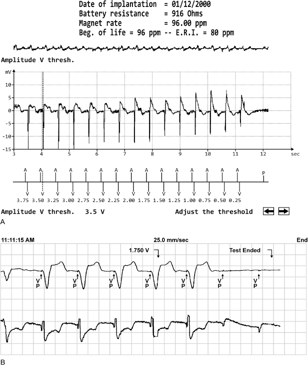
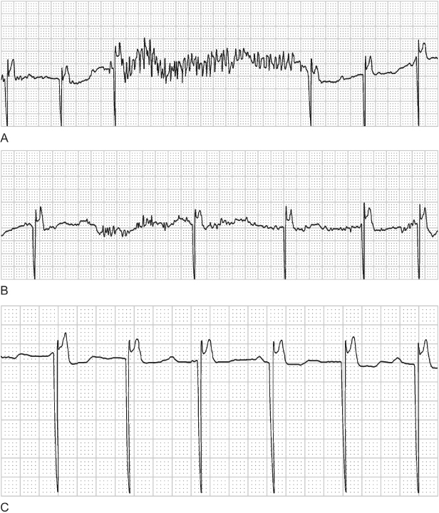
Pacing thresholds should then be evaluated. Most devices allow automated evaluation of pacing thresholds; the output is incrementally decreased until loss of capture occurs, and termination of the test results in immediate pacing at pretest values (Fig. 10.6). Pacing thresholds can always be obtained manually. In pacemaker-dependent patients, threshold testing should be performed in the safest possible manner which is usually a mechanism that results in the pacemaker reverting to the permanently programmed output when loss of capture noted. The operator should be familiar with the programmer emergency pacing feature should it become necessary to restore nominal pacing outputs quickly. After determination of the pacing threshold(s), the chronically programmed output parameters, i.e., voltage amplitude and pulse width, should be reassessed to be certain that the patient has an adequate safety margin. There are several ways to program output parameters to ensure an adequate safety margin. These are described in detail in Chapter 8: Programming. During the evaluation of pacing thresholds, the presence or absence of ventriculoatrial conduction should be noted, and the patient should be questioned about symptoms of pacemaker syndrome, especially if it is suspected on the basis of the clinical findings.
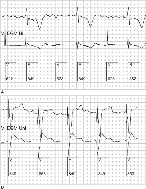
Fig. 10.6 Two examples of autothreshold determination by the programmer. Autothreshold determination allows ventricular thresholds to be determined in the pacemakerdependent patient, with minimal risk of clinically significant asystole. (A) Ventricular capture is maintained to the lowest value of 0.25 V. (B) Ventricular capture is lost at 1.75 V.
Threshold values should be compared with those at implantation if possible. The development of exit block, some medications, severe electrolyte or metabolic abnormalities, lead dislodgment, and occurrence of new myocardial infarction may affect pacing thresholds (Table 10.3).
Table 10.3 Effect of drugs on pacing thresholds.
| Increase in threshold |
| Bretylium |
| Encainide* |
| Flecainide |
| Moricizine* |
| Procainamide† |
| Propafenone |
| Sotalol |
| Decrease in threshold |
| Atropine |
| Epinephrine |
| Isoproterenol |
| Corticosteroids |
*Off market in the USA.
†At supratherapeutic levels.
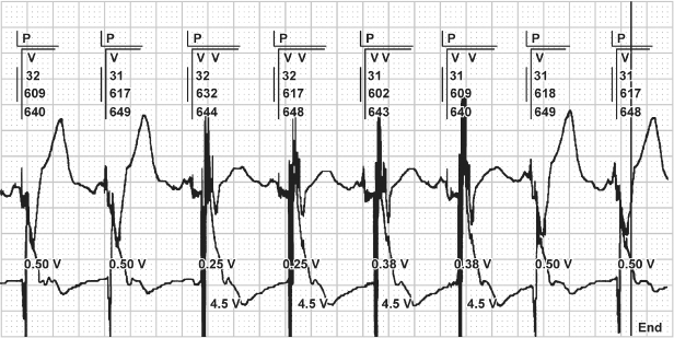
Many devices offer automated periodic assessment of pacing threshold in the ventricle, with adjustment of the pacing output to maintain capture with a safety margin that minimizes battery depletion (Fig. 10.7).2,3 In these devices, the output on the ventricular channel may be different at the time of interrogation from that initially programmed because of self-adjustment of the device. Additionally, electrocardiographic monitoring during a periodic threshold check may give the appearance of device malfunction due to variations in pacing outputs during the self-diagnostic test.
Fig. 10.7 Electrocardiographic tracing demonstrating automatic threshold determination. In this example, capture is lost at 0.25 V and the output is automatically increased to 0.38 V, which fails to capture, and the device again increases output to 0.5 V, and confirms capture for two consecutive beats. If one is not familiar with this specific function, it may suggest malfunction.
The sensing threshold in each chamber should be assessed. Some devices automatically measure the native atrial and ventricular electrograms,4 whereas in older devices the value may require manual measurement. The measured sensitivity should be compared with the programmed value to ensure that the chronically programmed sensitivity value is adequate.
Assessing the Pacing Rate
An understanding of basic pacemaker timing cycles is mandatory (explained in detail in Chapter 7: Timing Cycles). Many abnormal-appearing electrocardiograms actually represent normal device function when it is understood how the device is programmed.
To know whether the pacing rate is appropriate, it is first necessary to determine the pacing mode and programmed lower and (if applicable) upper rate limits. Under certain circumstances, the rate may be outside programmed values. The upper rate limit may be overridden by the spontaneous sinus rhythm, atrial or ventricular tachyarrhythmias, or, in very rare instances, runaway pacemaker (see later).
Several optional features allow intrinsic rates below the programmed lower rate limit to occur without pacing under specific circumstances. Some devices have a nocturnal or sleep function. During sleep time, the pacemaker allows programming of the lower rate limit to a rate generally 10 or 15 ppm less than that during wake time, replicating the natural circadian sleep–wake cycle. If it is not known that a “sleep rate” is programmed “on,” confusion may arise when the patient’s paced rate decreases at the programmed time.
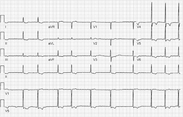
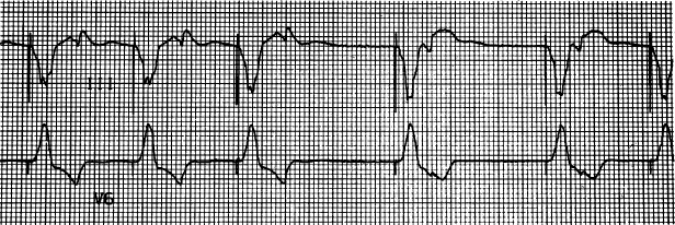
Hysteresis allows the intrinsic heart rate to decrease to a rate below the lower rate limit before pacing begins at the programmed lower rate (Fig. 10.8). However, if the intrinsic rate slows below the hysteresis rate, then pacing will commence at the lower rate limit (which by definition is faster than the hysteresis escape rate). Thus, hysteresis permits intrinsic rhythms slower than the programmed lower rate limit, but will not result in pacing at rates below the lower rate limit, distinguishing it from “sleep rate” function. Although useful in patients whose intrinsic rate approximates that of the programmed lower rate limit to promote native conduction, hysteresis has been a source of confusion for many years. Unless it is realized that hysteresis is programmed “on” and the mechanism of this feature is understood, electrocardiographic tracings are often misinterpreted as “oversensing,” because the cycle length is intermittently longer than the recognized programmed lower rate limit.
Fig. 10.8 A portion of a 12-lead ECG from a patient with a VVI pacemaker programmed to a pacing rate of 60 ppm, i.e., VV interval of 1000 ms. However, an interval of approximately 1240 ms is explained by a programmed hysteresis rate of 40 ppm, i.e., 1500 ms. This means that if an intrinsic QRS complex is present, the pacemaker will wait for 1500 ms to “time-out” before delivering the fi rst paced artifact. Once pacing has occurred, pacing will continue at the programmed lower rate, i.e., intervals of 1000 ms, unless intrinsic ventricular depolarization occurs and again initiates the hysteresis interval.
Multiple parameters affecting the AV intervals are programmable. Independently programmable paced and sensed AV intervals allow for more consistent mechanical AV activation in patients with interatrial and intra-atrial conduction delay, but can cause confusion when electrocardiographic tracings are interpreted. This effect may also cause minor variations in the paced lower and upper rates. Rate-adaptive AV delay is available in most dual-chamber pacemakers. Because the rate-adaptive AV interval affects the total atrial refractory period and therefore the achievable upper rate limit, confusion may arise (see Chapter 7: Timing Cycles).
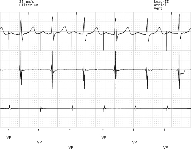
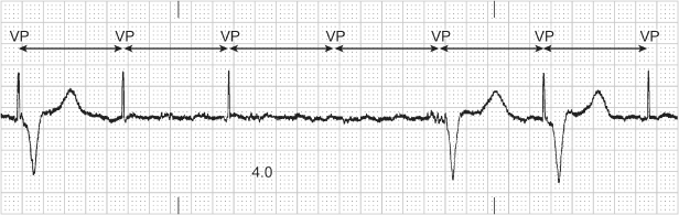
Another classic source of confusion during assessment of pacing rates and alterations in cycle length is rate smoothing. Rate smoothing avoids abrupt changes in pacing rate, such as those that can occur during a sudden transition to pseudo-Wenckebach or 2 : 1 upper rate behavior, and may eliminate symptoms associated with sensed dysrhythmic events. Rate smoothing controls sudden changes in pacing rate by monitoring the interval between ventricular events (both paced and sensed) and storing the most recent RR interval in memory (Fig. 10.9). On the basis of this RR interval and the programmed rate-smoothing percentage, the pulse generator sets up two rate-control windows for the next cycle – one for the atrium and one for the ventricle. For example, if the monitored VV interval is 800 ms and 6% rate smoothing is programmed, the algorithm allows the upcoming ventricular rate of the cycle to increase or decrease a maximum of 6%, or ±48 ms (752–848 ms). Rate stabilization algorithms function in an analogous manner to prevent long pauses, and similarly can result in “unexpected” pacing on the surface ECG.
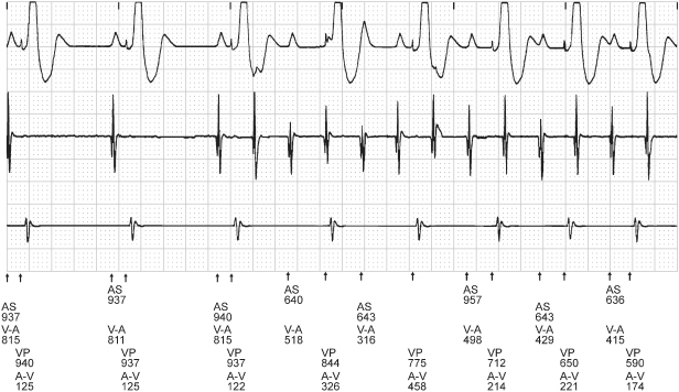
Fig. 10.9 Rate smoothing can confound electrocardiographic interpretation if one is not familiar with it or aware that it is programmed “on.” In this tracing, normal sinus rhythm is replaced by an atrial tachyarrhythmia. Rather than an abrupt increase in the paced ventricular rate in response to the atrial tachyarrhythmia, there is gradual shortening of the VV cycle length. The cycle length is regulated by rate smoothing and is allowed to change by the programmed smoothing factor; in this example, the smoothing factor is 9%. AS, atrial sensing; V-A, interval from ventricular sensed or paced event to atrial paced event; VP, ventricular pacing.
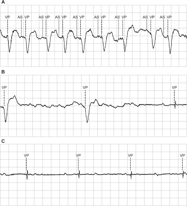
Other algorithms also result in “unexpected” atrial pacing or intrinsic conduction. For example, atrial fibrillation (AF) suppression algorithms may maintain atrial pacing at a rate slightly faster than the intrinsic rate, and periodically extends the cycle length to reassess the intrinsic rate.5 Once intrinsic conduction is seen, the rate is again increased to maintain atrial pacing. Thus, surface electrocardiography reveals predominantly paced atrial rhythms with spontaneously slow, up to two conducted intrinsic beats, and then more rapid atrial pacing. Ventricular avoidance pacing algorithms may also result in tracings with predominantly paced atrial rhythms with what may appear to be inappropriate lack of ventricular pacing artifacts.6
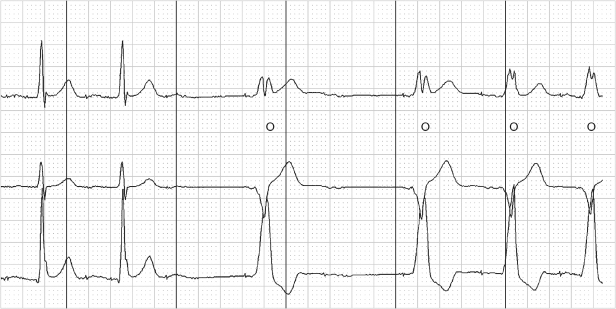
Most manufacturers have some variation of rate drop response or sudden brady response, designed primarily for patients with neurocardiogenic syncope. This type of feature is triggered when the native heart rate decreases through a programmed rate-drop window, after which the device paces at a faster programmed rate (generally 90–100 ppm) until spontaneous rhythm is detected. Other devices offer some type of search hysteresis, in which the device paces for a programmed number of cycles at an accelerated rate (usually 90–100 pulses/min) when the native rate drops below the lower rate limit. Search hysteresis can lead to misinterpretation of the electrocardiogram if the feature is not well understood or if the healthcare professional interpreting the electrocardiogram is unaware that the feature is programmed “on” (Fig. 10.10).
Fig. 10.10 Sudden onset of pacing at a rate of 100 ppm. This occurs as a result of a sudden bradycardia response, i.e., a pacemaker feature that will pace at a faster rate for a programmed period of time when there is a drop in heart rate that meets preset criteria of the algorithm. The purpose of this feature is to better support the patient’s blood pressure when neurocardiogenic responses result in cardio-inhibition, which is often accompanied by vasodepression.
Rate-adaptive sensors can also cause confusion. Sensors based on physiologic stimuli, such as thoracic impedance or intracardiac impedance measurements, may increase the pacing rate even when the patient is not physically active (as with activity-based sensors). The sensor-driven rates may therefore cause confusion because the paced rates may seem inappropriate for a given activity (Fig. 10.11). Patients may experience symptoms of fatigue or effort intolerance if the sensor is not programmed aggressively enough and symptoms of palpitations or tachycardia if it is programmed too aggressively (see Chapter 9: Rate-Adaptive Pacing).
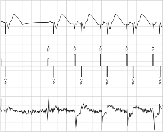
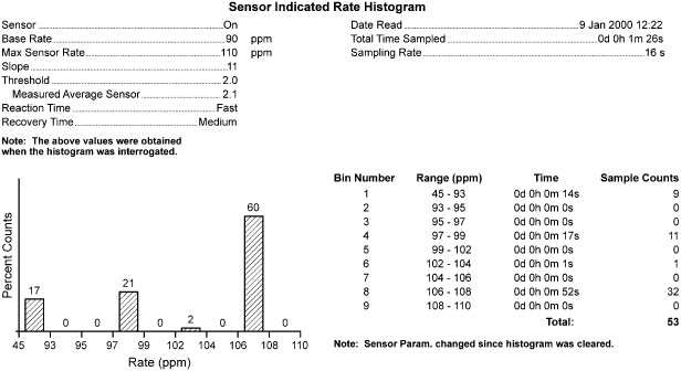
Fig. 10.11 Inappropriate sensor response is determined from the “Sensor Indicated Rate Histogram.” During a casual walk of 1 min 26 s, the patient’s heart rate varied from the lowest rate bin to a point near the maximum sensor rate of 110. Sixty percent of the counts were in the 106–108 ppm rate bin. The patient complained of dyspnea during the casual walk. With reprogramming to less aggressive rate-adaptive parameters, the walk was well tolerated.
Diagnostic Features
Most contemporary devices offer sophisticated diagnostic options that can help troubleshoot potential causes of clinical events and aid in optimal programming and detection of potential problems before symptoms develop.7–9 Such diagnostic features include the number of mode-switching events, number of high-rate atrial events, number of ventricular high-rate episodes, number of ectopic events, percentage of time paced and sensed in all chambers, electrograms, and trending of such values as lead impedance.
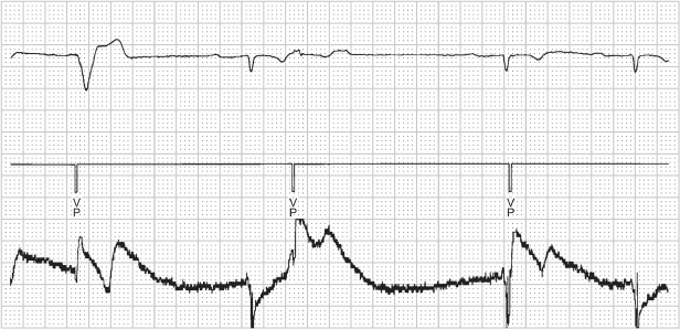
Pacemakers provide diagnostic interpretation channels. An electrocardiographic recorder from the programmer is applied to the patient, and telemetry is established with the pacemaker. The marker channel offers real-time, simultaneous electrocardiographic signals and markers denoting paced and sensed events as well as refractory events occurring in each channel. This feature is especially helpful in attempting to determine whether the device is undersensing or oversensing, or if “functional” sensing abnormalities exist (Fig. 10.12).
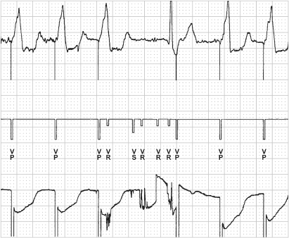
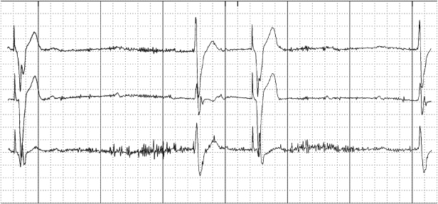
Fig. 10.12 Programmer-derived tracing with: top, surface ECG; middle, marker channel; bottom, ventricular electrogram. On the surface ECG there is a VV interval that is longer than any other interval present on the tracing. On the marker channel the pause correlates with multiple ventricular sensed events (VS) and ventricular events that occur in a refractory period (VR). This represents oversensing that was caused by a conductor coil fracture. Although oversensing would be suspected based on the surface tracing alone, the marker channels confirm oversensing and provide diagnostic information as to the mechanism. The sharp, saturated electrograms are consistent with “make-break” contact noise from a fracture site.
In nonpacemaker-dependent patients who have experienced a clinical event suggesting possible pacing system failure which is not identified by a thorough noninvasive evaluation, Holter monitoring or an event recorder may be considered (Fig. 10.13).
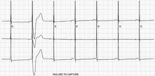
Fig. 10.13 Three-channel tracing from an ambulatory monitor that was obtained because the patient had recurrent symptoms after pacemaker implantation. The tracing demonstrates failure to capture and the pacemaker malfunction correlated with symptoms. The patient was found to have developed excessively high pacing thresholds on epicardial pacing leads.
Battery voltage should always be assessed during troubleshooting. Battery depletion, although expected, is still the most common cause of pacemaker failure.1 Some devices provide a measured numerical battery voltage, which should generally be above 2.4 V in lithium-based batteries, and others give a “gas gauge” representation of battery status. Another way to grossly assess battery voltage is to note the magnet rate. All pacemakers have a characteristic magnet rate that changes predictably as the battery voltage decreases. Unfortunately, each manufacturer uses a different magnet rate, necessitating knowledge of or access to that information to ascertain battery status. Assessment of the magnet rate is a key component in transtelephonic pacemaker monitoring. As the battery approaches depletion, most devices reset to a backup mode. Backup mode is usually fixed-rate ventricular pacing at maximal output. Most devices also lose telemetry function and programmability when the battery nears imminent failure.
Unexpected Device Failure
Contemporary pacemakers and implantable cardioverter-defibrillators (ICDs) have achieved an extraordinary level of reliability. However, rare random component failures occur.1
If a component malfunction is suspected, the manufacturer should be asked whether similar problems have been reported. Physicians should report adverse device events via the FDA’s MedWatch program using a simple online form (https://www.accessdata.fda.gov/scripts/medwatch/). Other sources of information also exist. There is no comprehensive, mandatory database of pacemaker pulse generator and lead usage and function at present in the USA.
Operative Evaluation of Pacing Systems
Sometimes the status of a pacing system is impossible to determine noninvasively. If intermittent system failure is strongly suspected clinically and comprehensive noninvasive evaluation has been unrevealing, operative assessment may be required.
Invasive troubleshooting should begin with pulse generator manipulation in the open pocket while the electrocardiogram is observed for abnormalities in pacing or sensing. After delivery of the generator from the pocket, the connection between the pins and the setscrews should be inspected. The lead or leads should then be disconnected from the pulse generator, and thresholds, current, and impedance should be directly measured by the pacing system analyzer before any further manipulation of the leads. Normally, only minor variation exists between the values obtained by telemetry and those obtained by direct measurement; gross differences suggest lead abnormalities. One of the most important measurements obtained at the time of intraoperative troubleshooting is lead impedance. After the electrical integrity of the lead is assessed, the leads should be carefully dissected away from any fibrous tissue and visually inspected. Any obvious breaks in the insulation or fractures in the coil should be noted, especially in the area under any anchoring or purse-string sutures. Blood in the lead is de facto evidence of a breach in the insulation. Unfortunately, only that portion of the lead that is extravascular can be visually inspected. Any breach of lead integrity would likely warrant lead replacement. Attempting lead repair is rarely, if ever, the best approach.
However, one is sometimes left with a clinical situation strongly suggestive of pacing system malfunction and no obvious point of failure. In that case, careful consideration could be given to empirically placing a new lead, especially the ventricular lead in a pacemaker-dependent patient. However, empiric replacement of any portion of the pacing system should be considered only as a last resort.
Focused Troubleshooting
Now that the broader troubleshooting issues have been discussed, we focus on specific, presenting clinical problems. Most problems can be categorized by electrocardiographic abnormalities:
- Failure to capture
- Failure to output
- Undersensing
- Alteration of pacing rate.
Or by patient symptoms:
- Syncope or near-syncope
- Palpitations
- Fatigue.
Each category is discussed after a differential diagnosis has been provided. Some problems occur more commonly early after implantation (i.e., within the first few weeks post-implant), some much later, and others completely independent of time. An attempt is made to classify each abnormality by whether it is most likely to occur early, late, or at any time after implantation.
Failure to Capture
The differential for failure to capture and the most likely time of appearance for the abnormality are as follows:
| Early At any time After the first 4–6 weeks Acute (usually manifest within 48 h) Usually late Usually late Usually early Usually late At any time Acute At any time At any time |
Fig. 10.14 Surface ECG (top) and unipolar ventricular electrogram (bottom) from a patient who presented with ventricular failure to output at a routine followup. No ventricular pacing artifacts could be seen on the surface ECG when programmed to DDD or DOO mode. This tracing, obtained in a DDD mode, demonstrates that the pacemaker is delivering atrial and ventricular outputs. However, failure of the ventricular pacing output to be seen on the surface ECG suggests that the circuit is interrupted. In this case the chest X-ray demonstrated a connector pin that was not fully engaged in the connector block.
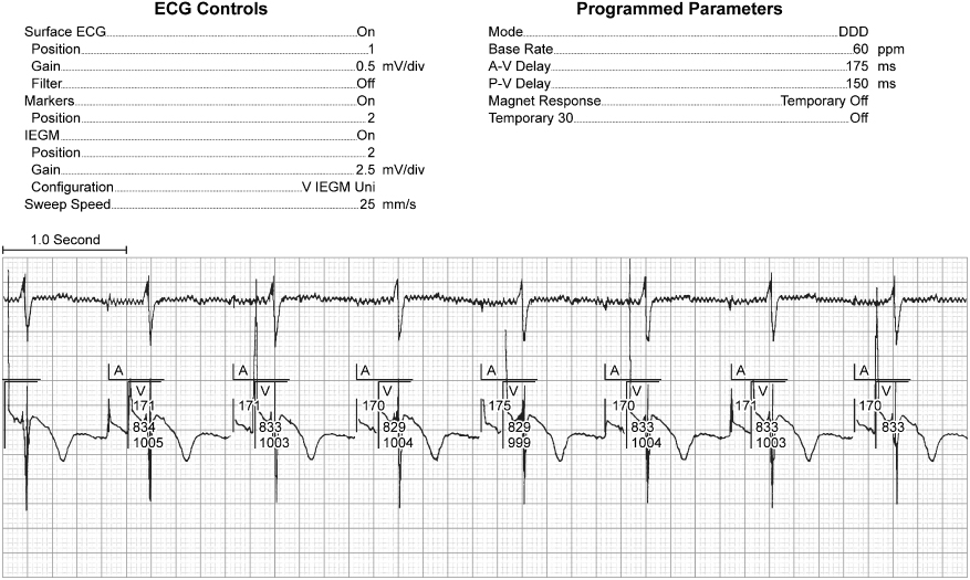
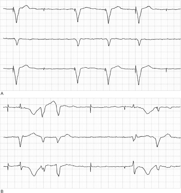
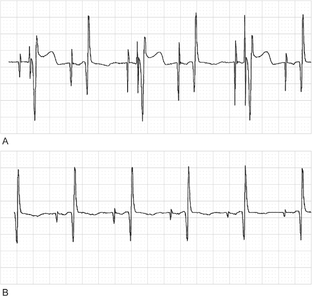
Fig. 10.15 (A) Electrocardiographic tracing from a patient with a ventricular pacemaker and recurrent near-syncope. The patient had not had her pacemaker checked in several years. The electrocardiogram reveals intermittent failure to capture, and troubleshooting results were consistent with nearly total battery depletion. (B) The patient was admitted to the hospital, and a subsequent tracing demonstrated complete failure to capture and ventricular rhythm disturbances secondary to the bradycardia. At the time of pulse generator replacement, lead function was normal.
A clinical approach to assessment of the most common causes of failure to capture is detailed in Table 10.4.
Table 10.4 Failure to capture.
| Determine pacing threshold |
| Able to obtain consistent capture at higher output – yes or no |
| Check impedance |
| If low – recheck in unipolar configuration |
|
| If high – recheck in unipolar configuration |
|
| If normal – obtain chest X-ray to look for dislodgment |
|
Lead dislodgment usually occurs within the first few weeks after implantation. It may be microdislodgment or macrodislodgment. Macrodislodgment implies that the problem is radiographically evident. Microdislodgment implies that the clinical situation is consistent with dislodgment, but that there is no radiographic evidence that the lead has moved (see Chapter 6: Implant-Related Complications).
With lead dislodgment, failure to capture may be intermittent or persistent. It is often, but not always, accompanied by sensing abnormalities (Fig. 10.16). If macrodislodgment is confirmed, the lead should be repositioned. The diagnosis of microdislodgment should be entertained and the lead repositioned only if other causes of failure to capture have been excluded.
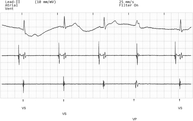
Fig. 10.16 Tracing from a patient with the pulse generator programmed to VVI at a rate of 30 ppm. The surface tracing, top, reveals a single paced beat and corresponds to a ventricular pace (VP) marker. (The second tracing from the top represents the atrial electrogram and the bottom tracing represents the ventricular electrogram.) It is important to take advantage of all of the information offered by the pacemaker, but it is just as important to take advantage of information “not provided” by the pulse generator. In this example, all of the ventricular events are labeled on the marker channel with the exception of the third ventricular event. This is because the event was not sensed and therefore not labeled as a VS event. The interval from the paced event backward to the second event equals approximately 2000 ms or 30 ppm.
In Fig. 10.17, atrial lead dislodgment leads to cross-stimulation. Cross-stimulation is defined as stimulation of a cardiac chamber different from the one to which the stimulus is directed. This may result from atrial lead dislodgment into the ventricle or from atrial lead stimulation near the tricuspid valve or in the coronary sinus. Cross-stimulation as a reversal of lead connection may also occur but is uncommonly reported (Fig. 10.18).
Fig. 10.17 (A) Electrocardiographic tracing shortly after the implantation of a dual-chamber pacemaker. The tracing confirms atrial and ventricular capture. (B) Electrocardiographic tracing from the same patient at a 4-week follow-up examination. The atrial pacing artifact results in ventricular stimulation, and the ventricular artifact occurs at the same atrioventricular interval but falls after the ventricular depolarization. Chest radiography confirmed that the atrial lead had dislodged into the ventricular lead. Because the intrinsic deflection of the ventricular depolarization was consistently falling within the blanking period, the atrioventricular interval was not disturbed.
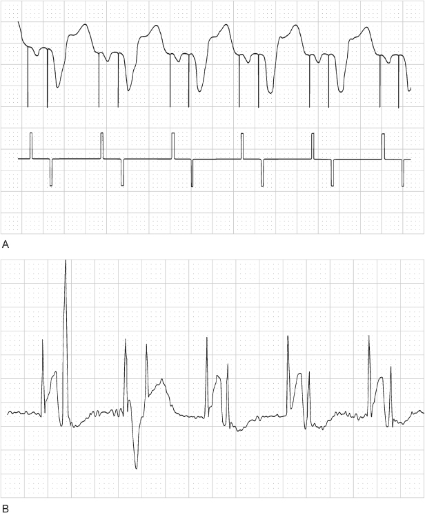
Fig. 10.18 Telemetry from a dualchamber pacemaker; top channel is surface ECG; second channel atrial electrogram; third channel ventricular electrogram and bottom channel is of “markers.” The pacemaker is programmed to the VVI mode during this tracing, but there is consistent atrial pacing and the ventricular EGM channel actually displays the atrial electrogram. The ventricular lead had been connected to the atrial port of the dual-chamber pacemaker and the atrial lead connected to the ventricular port.
Elevated thresholds may be due to a variety of causes, including lead dislodgment, perforation, loss of lead integrity (e.g., fracture or insulation defect), damage at the electrode–myocardium interface and metabolic, electrolyte, or drug changes (Fig. 10.13). Although the etiology of the elevated pacing threshold must be determined and managed, as a temporary measure an attempt should be made to re-establish capture by increasing output parameters.
Damage at the electrode–myocardial interface may occur from several causes. Myocardial infarction, an infiltrative cardiomyopathic process, or localized damage secondary to cardioversion or defibrillation could damage the myocardium at the site of the electrode.10 With an infiltrative process, the alteration in pacing or sensing threshold may be permanent. Following myocardial infarction, cardioversion, or defibrillation, the changes may be transient or permanent.
Altered pacing-sensing thresholds after cardioversion-defibrillation occur if the electrical current is transmitted through the lead and results in a circumscribed burn at the electrode–myocardial interface (Fig. 10.19). The threshold alteration is usually transient, minutes or hours. The potential risk may be minimized, but not completely eliminated, by maximizing the distance between the cardioversion pads and the implanted device.
Fig. 10.19 (A) Baseline electrocardiographic tracing from a patient with a dual-chamber pacemaker with underlying atrial fibrillation. (The “marker” notations have been added to facilitate interpretation of the tracing.) The atrial fibrillation is being tracked by the ventricular channel, resulting in an irregular paced ventricular rhythm. (B) The pacemaker has been programmed to a VVI mode at a rate of 30 bpm and the patient has been cardioverted using the precautions discussed in the text. However, despite all precautions being taken, the pacemaker is not functioning as programmed with apparent paced rates that are less than the programmed 30 bpm and failure to capture with the third pacing artifact. Also notes atrial fibrillation persists at this point. (C) Tracing obtained shortly after the one shown in panel B now demonstrates an underlying sinus rhythm. However, there is complete failure to capture. An emergency temporary pacing wire was placed but within a very short period of time the ventricular pacing threshold improved and ventricular capture was consistent via the permanent pacemaker and the temporary wire removed. However, no atrial functions could be restored on the pacemaker consistent with permanent damage to the pacemaker during the cardioversion. The pulse generator was replaced and chronic pacing and sensing thresholds on both leads were acceptable.
Exit block, by definition, is manifested as increased thresholds. Exit block is defined as chronically elevated thresholds, presumably due to excessive fibrosis or some other problem at the electrode–myocardial interface. True exit block is uncommon, and the cause is not well understood. Steroid-eluting leads generally, but not always, prevent exit block. The diagnostic problem is trying to differentiate exit block from microdislodgment. If microdislodgment is the presumed diagnosis, the lead is repositioned and thresholds improve and are maintained long term, microdislodgment is confirmed as the correct diagnosis. If exit block is the real problem, the thresholds will rise again. If this occurs with steroid-eluting leads, the only option is to program the pacing output to levels that allow consistent pacing and maintain an adequate safety margin. Most contemporary pacemakers can be programmed to maximum outputs of approximately 7.5 V and 1.5 ms. If capture cannot be maintained at these levels, therapeutic options are limited. Repositioning the ventricular lead or placing a new lead in an alternative ventricular site may be successful. Alternatively, coronary sinus pacing may be considered with long-term outcomes of coronary sinus pacing becoming more predictable.11 Epicardial pacing could also be considered even though epicardial thresholds are characteristically higher than endocardial thresholds, which may not be the case in the patient with exit block on a transvenous lead. Again, long-term outcome cannot be predicted and only long-term observation will determine success.
The use of systemic steroids to treat high outputs may be contemplated. Large doses of systemic steroids usually result in a decrement in pacing thresholds. However, when administration is discontinued, the thresholds generally increase again. Long-term use of steroids is obviously not desirable because of the systemic side effects.
Perforation may also cause elevated thresholds and is discussed in Chapter 6: Implant-Related Complications.
Metabolic and drug alterations may also affect thresholds and result in failure to capture.12–20 Drugs that may affect pacing thresholds are listed in Table 10.3. Two comments should be made about drug therapy. Class IC antiarrhythmic agents are the most likely drugs to affect pacing thresholds. If a pacemaker-dependent patient is placed on a Class IC agent, administration should be done cautiously and the patient’s course followed carefully. This class of drugs may also affect sensing thresholds (Fig. 10.20).13–15,21
Fig. 10.20 Series of electrocardiographic tracings from a patient who received a dual-chamber pacemaker for tachycardia-bradycardia syndrome. The top tracing, obtained on day 1 post-implant, reveals dual-chamber pacing with atrial capture and ventricular fusion or pseudo-fusion. (Without an intrinsic ventricular event, it is impossible to state with certainty whether any degree of fusion exists.) The second tracing, obtained on day 5 post-implant, demonstrates a flat line that suggests an artifact. In fact, a monitoring electrode had fallen off, resulting in 21 s of artifactual recording. The third tracing, obtained on day 6 post-implant, reveals intermittent ventricular failure to sense and capture. The underlying rhythm appears to be atrial fibrillation. The bottom tracing, obtained on day 7 post-implant, suggests intermittent failure to capture and sense in both chambers. Administration of propafenone had been started for treatment of tachyarrhythmias. The drug resulted in significant elevation of both pacing and sensing thresholds.
A common misconception is that amiodarone will frequently result in an increase in pacing thresholds. Amiodarone can raise pacing thresholds secondary to drug-induced hypothyroidism.17 In the euthyroid patient, amiodarone rarely if ever causes elevated pacing thresholds.
Most severe metabolic disturbances can affect pacing and sensing thresholds.22–25 Hyperkalemia is the most commonly encountered metabolic disturbance to do so. The most frequent clinical scenario is in the pacemaker patient who is undergoing dialysis. Although programming output or sensing variables may help in the short term, the definitive treatment is to lower the potassium levels and avoid subsequent episodes of hyperkalemia.
Older studies have documented sensing and pacing threshold variations with such everyday activities as sleeping and eating.15–17 Although well documented, the threshold variations are minimal. In addition, with the low achievable pacing thresholds and outstanding sensing thresholds achievable with contemporary pacing systems as well as a broad range of programming options, the issue is rarely clinically significant.
Loose setscrew can cause failure to capture. Although this is usually detected in the early post-implantation period, a setscrew that has not been effectively tightened may not work loose for months. The clinical presentation of a loose setscrew depends on the degree of contact between the connector pin and the header. If the header and pin are completely disconnected, complete failure to output occurs because of the circuit interruption. If failure of contact is intermittent, failure to output is also intermittent (Fig. 10.14). Although this is the most common presentation, minimal contact between pin and header may allow transmission of a pacing artifact but inadequate energy is transmitted to result in capture. Intermittent contact may also lead to oversensing with consequent inhibition of pacing.
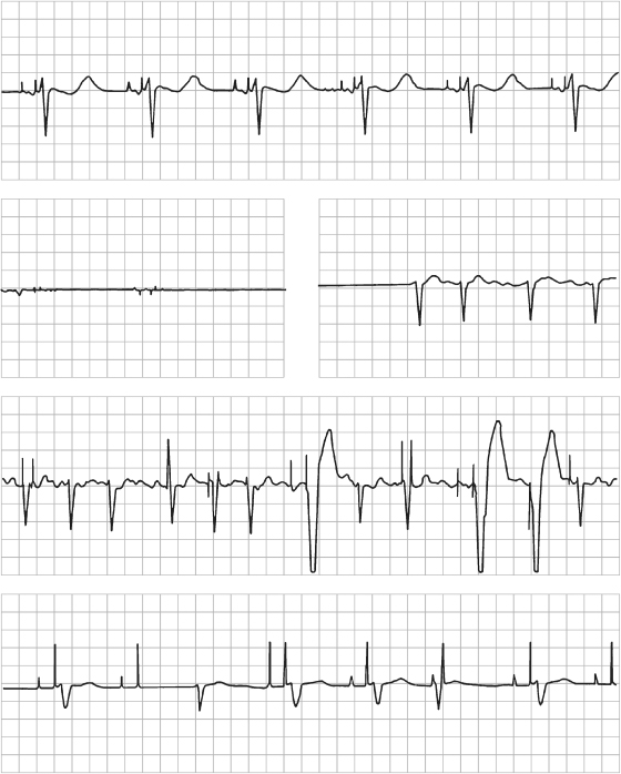
Conductor coil fracture may produce failure to capture, failure to output, and sensing abnormalities (Fig. 10.21). Although this could theoretically happen at any time, it is most often a “late” or chronic complication. In complete fracture, the electrocardiographic findings are persistent. In “make-or-break” fracture, the electrocardiographic abnormalities are intermittent. If the fracture is complete, i.e., the circuit is interrupted, failure to output occurs. If the break is incomplete, i.e., only a portion of the output pulse is transmitted to the heart, failure to capture is seen. Often, both manifestations are present. Escaping current at the “break” may also cause sensing abnormalities.
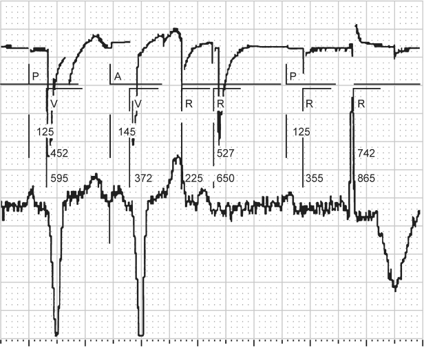
Fig. 10.21 Electrocardiographic tracing obtained by the programmer in a patient with a ventricular lead fracture. The electrogram identifi es intrinsic ventricular events (R) where none occur, because escaping current is sensed by the pacemaker and identified as a ventricular event. There is evidence of failure to capture, identified by a paced ventricular output (V) without a corresponding paced ventricular event on the surface electrocardiogram (lower tracing). Also, there is functional atrial undersensing, i.e., intrinsic P waves are not sensed because the post-ventricular atrial refractory period (PVARP) has been extended. The electrogram (upper tracing) is erratic because of the lead fracture. P, intrinsic atrial event; A, paced atrial event.
Although programming a bipolar lead to a unipolar pacing and sensing configuration may restore normal pacing, this “fix” should be considered temporary (Fig. 10.22). Whatever mechanism fractured the outer coil of a coaxial lead could eventually affect the inner coil also.
Fig. 10.22 (A) Programmer-derived surface electrocardiogram, ventricular bipolar intracardiac electrogram, and markers demonstrating VVI pacing at 70 ppm with failure to capture. Telemetered ventricular impedance was >9999 Ω. (B) Reprogrammed to the unipolar pacing configuration at the same output settings, ventricular capture is now consistent and the lead impedance is within normal range.
Insulation break also can produce a variety of clinical manifestations and is most often a “late” complication. Insulation defects may involve the outer insulation or, in a bipolar lead, the insulation between conductors. Sensing abnormalities are the most common electrocardiographic manifestation.1 These can be diagnosed as a reduction in bipolar lead impedance with normal uinpolar impedance in leads at risk for this failure mode. Failure to capture and failure to output, intermittent or persistent, may also be seen (Figs 10.23 and 10.24).
Fig. 10.23 Electrocardiographic tracing obtained from a patient with an older ventricular polyurethane pacing lead on advisory. There is intermittent ventricular failure to capture. The finding is relatively subtle. The second and fourth ventricular events are paced. The other ventricular events are intrinsic. The ventricular pacing artifact precedes the intrinsic ventricular events, but fails to capture. Interrogation revealed a lead impedance of <250 Ω.
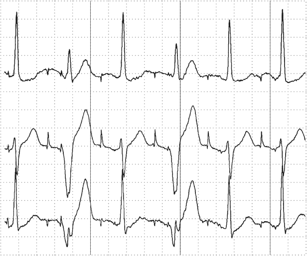
Fig. 10.24 Electrocardiographic tracing obtained from a patient with a pacing lead on advisory due to an unacceptable incidence of insulation failure. In this example, there are two pauses. The intervals are not exact multiples of the paced VV cycle (the distance from the second to third ventricular event). Without marker channel or intracardiac electrograms, it is not possible to say whether this is an example of oversensing or whether there is an undetected paced ventricular artifact with failure to capture. However, with the lead advisory, the possibility of a defective lead is difficult to ignore.
As with conductor coil fracture, programming a bipolar lead to unipolar pacing and sensing configuration may restore normal pacing and sensing. If the insulation defect is in a ventricular lead in a pacemaker-dependent patient, even if programming to a unipolar configuration restores normal function, this should be considered a temporary solution and the lead should be replaced.
Battery depletion is an expected late occurrence.1 Fortunately, battery depletion is almost always a predictable phenomenon, one that is readily detected as part of a regular follow-up program.26 Some pulse generators have had battery depletion patterns that were unpredictable or earlier than projected. If a pulse generator is known to have unpredictable or sudden battery failure, the device should be prophylactically replaced, following guidelines provided by the manufacturer.
Air in the pocket is a complication that is rarely seen but may result in a pacing failure if the pacemaker is functioning in a unipolar pacing configuration. Because a pacemaker in the unipolar pacing configuration must make tissue contact to complete the circuit, air can insulate the pacemaker and prevent tissue contact. Historically, this was of greater potential when one side of the pacemaker was coated and the coated side was placed next to the underlying muscle. This meant that contact had to be maintained with the anterior portion of the pulse generator. This is no longer the case and any surface of the device programmed to the unipolar configuration that is in contact with tissue should maintain normal function. Therefore, even if there was air or fluid anterior to the pulse generator that prevented tissue contact, it would still be maintained on the posterior surface.
Circuit or component failure is rare. Contemporary pacemakers have achieved an extraordinary level of reliability. If a circuit or component failure occurs, the clinical manifestation is usually not predictable and almost any electrocardiographic abnormality is possible.26
Pseudo-Malfunctions
Several pseudo-malfunctions may suggest failure to capture. Functional failure to capture occurs if a pacing artifact is delivered when the ventricle is functionally refractory. For example, during magnet application and asynchronous pacing, a pacing artifact that occurs early after an intrinsic event will not capture the myocardium (Fig. 10.25).
Fig. 10.25 Single-lead electrocardiographic tracing from a patient programmed to a VVI mode but obtained during magnet application, i.e. VOO. The first ventricular paced event (VP) results in ventricular capture. The second VP occurs approximately 360 ms after an intrinsic ventricular event. The myocardium is refractory from the intrinsic depolarization which results in “functional” failure to capture. The third VP appears to occur simultaneously with an intrinsic beat but there is no alteration in intrinsic QRS morphology, i.e. pseudo-fusion beat results.
Isoelectric atrial or ventricular depolarization may suggest failure to capture; i.e., a pacing artifact is recorded but there is minimal, if any, electrocardiographic evidence of depolarization (Fig. 10.26).22 Confirmation can be obtained by a multichannel recording (Fig. 10.27).
Fig. 10.26 Transtelephonic tracing with magnet application. The first magnet beat is labeled “1.” There is failure to capture on the “third” magnet evoked pacing artifact. On the beat that follows, 4, it is difficult to separate a paced QRS from the pacing artifact. Given the accepted variation of pacemaker artifact size when a digital recording system is used, it would be possible to assume that the artifact was a larger variation of the artifact seen in beat 3 and that there was again failure to capture. However, the artifact labeled “4” is followed by a definite T wave. If there is repolarization there had to be depolarization. Therefore, capture was normal with the artifact labeled “4.”
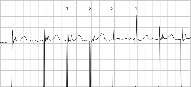
Fig. 10.27 Three-channel electrocardiographic tracing from a patient with P-synchronous pacing. If the top tracing is viewed in isolation, it is difficult to tell which chamber is paced and if there is capture. However, a clue in the top recording is that there appears to be ventricular repolarization, i.e., a T wave; therefore, there must have been depolarization, even if the QRS is difficult to identify.
Electrical artifact, i.e., nonpacemaker output artifact, may be misinterpreted as being pacemaker artifact and therefore may suggest failure to capture. Electrical artifact can present in many ways. If there is very regular and very rapid artifact present, one should be suspicious of 60-cycle interference. The first question to ask is whether the patient is symptomatic. If not, then before reacting to the electrocardiographic finding, look for and disable any possible source of electrical interference (Fig. 10.28).
Fig. 10.28 Artifact noted in this tracing obtained during a medical procedure. The patient was asymptomatic. There was a source of 60-cycle interference in the procedure room. When this equipment was turned off, the electrical artifact stopped.
Failure to Pace (No Output)
- Battery failure
- Circuit failure
- Lead fracture
- Insulation failure
- Oversensing
- Loose setscrew
- Crosstalk
- Unipolar lead with pulse generator programmed to bipolar configuration
- Pseudo-malfunction:
- Ventricular pacing avoidance algorithm
- Small bipolar pacing artifacts
- Sleep function (reduction in rate under specific circumstances)
- Isoelectric intrinsic rhythm.
- Ventricular pacing avoidance algorithm
A clinical approach to assessment of the most common causes of failure to output is detailed in Table 10.5.
Table 10.5 Failure to pace (output).
| Assess multichannel electrocardiogram to determine whether pacing artifacts may be visible in one lead but not another – if artifacts are indeed present, no further evaluation needed |
| Reprogram the pulse generator to high output settings and to a pacing rate that is unequivocally faster than the patient’s underlying rhythm |
| Obtain telemetry with markers |
|
| Invasive troubleshooting will probably be necessary at this point |
|
Battery failure (Fig. 10.15), circuit or component failure, lead fracture, insulation defect, and loose setscrew have all been discussed as potential causes of failure to output.
The most common cause of failure to output is oversensing. Oversensing implies that something is sensed other than an intrinsic atrial or ventricular depolarization, and therefore the timing cycle is reset and the pacing output inhibited (Fig. 10.29). As previously noted, oversensing may be a manifestation of lead failure, either conductor coil fracture or insulation defect (Fig. 10.24).
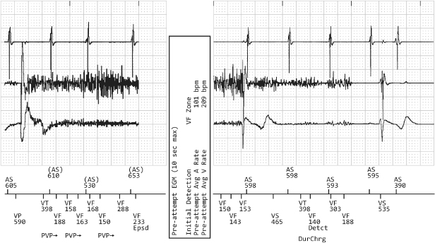
Fig. 10.29 Electrocardiographic tracing from ICD interrogation. Upper tracing, atrial electrogram; middle tracing, ventricular electrogram; lower tracing, surface electrocardiogram; marker channel at the bottom of the figure. There is significant artifact/noise on the ventricular EGM resulting in inhibition of ventricular pacing because the noise is oversensed as ventricular activity and classified as ventricular tachyarrhythmia, i.e., VT, VF.
Crosstalk occurs when an atrial pacing output is sensed on the ventricular sensing channel, inhibiting ventricular output (Figs 10.30–10.32). Mechanisms that contribute to crosstalk include high atrial output, ventricular sensitivity programmed to a very sensitive value, and positioning of atrial and ventricular leads in close proximity.
Fig. 10.30 Electrocardiographic example of “crosstalk.” Although crosstalk appears to be the most likely cause of ventricular failure to output when the surface electrocardiogram is assessed, it is confirmed by the telemetered “ladder diagram.” The ladder diagram, a type of diagnostic channel that is not commonly seen with contemporary devices, confirms that the atrial output was detected almost simultaneously on the ventricular sensing channel and that ventricular output was inhibited. P, paced; S, sensed.
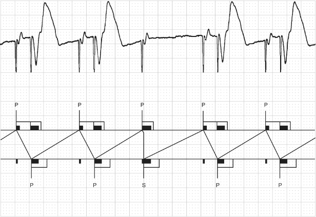
Fig. 10.31 Three-channel tracing from an ambulatory monitor. The tracing begins with AV sequential pacing with a short AV interval, approximately 100 ms, which probably represents ventricular safety pacing, although this cannot be proven without more diagnostic information and programming information. This is followed by an intrinsic atrial depolarization with ventricular tracking. The next event is an atrial paced event without a subsequent ventricular event, i.e., ventricular output inhibition. This is again followed by two cycles of AV sequential pacing, again with a relatively short AV interval. The paced AA interval is consistent between the final two intervals on the tracing. The ventricular failure to output could represent some event that was oversensed on the ventricular sensing channel. However, the consistency of the AA interval and the lack of any artifact on any of the three channels would suggest that oversensing of external noise or an isoelectric event is less likely and crosstalk more likely. If the other AV intervals reflect safety pacing then it is possible that whatever is being sensed as crosstalk during these cycles is instead being sensed beyond the crosstalk sensing window and inhibiting output.
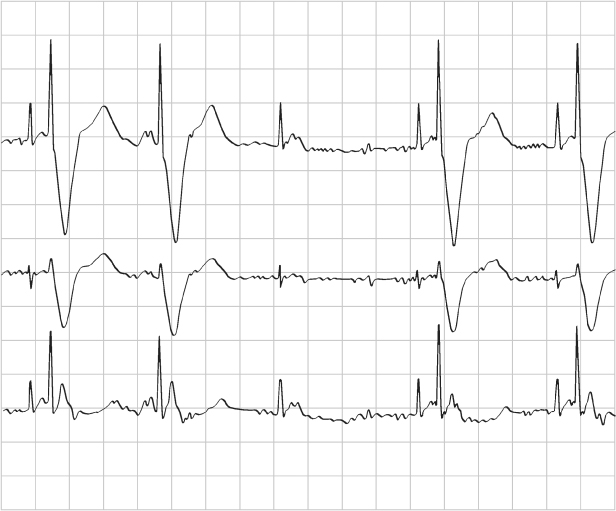
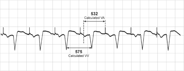
Fig. 10.32 Single-lead tracing from a patient with a dualchamber pacemaker programmed to the DDI mode and a rate of 86 ppm, AVI 165 ms and a ventricular blanking period of 13 ms. The tracing demonstrates a ventricular rate of approximately 104 ppm, RR interval = 575 ms. If the programmed rate is supposed to be 697 ms (86 ppm), the VA interval should be 697 ms – 165 ms (programmed AVI) = 532 ms. However, the effective rate is at a cycle length of 575 ms. 575 ms – the calculated VA interval of 532 ms = AVI of 43 ms. This means that there was sensing of ventricular activity at 43 ms after the atrial output which terminated the AVI and initiated the VA interval. This occurred because there was consistent sensing of the atrial output on the ventricular sensing channel, i.e., crosstalk, but the tracing appears relatively normal because the patient has consistent, albeit prolonged, AV conduction. The abnormality is only clear once the programmed parameters are known.
In an effort to prevent crosstalk, pacemakers incorporate a post-atrial ventricular blanking period (see Chapter 7: Timing Cycles). The blanking period is the initial portion of the AV interval. During this period, decay of the atrial pacing output is maximal and the atrial output has the greatest potential for being sensed on the ventricular channel. If something is sensed immediately after the blanking period, it is not possible to distinguish between crosstalk and an intrinsic event. As a safety measure, dual-chamber pacemakers deliver a ventricular pacing artifact at a foreshortened AV interval if something is sensed in the interval after the blanking period. This portion of the AV interval has been dubbed the crosstalk sensing window. If something is sensed in the crosstalk sensing window, ventricular safety pacing results in effective ventricular capture at a short AV interval, usually 100–110 ms, and prevents ventricular asystole (Fig. 10.33). If an intrinsic ventricular event is sensed in the crosstalk sensing window, e.g., a premature ventricular contraction, the ventricular safety pacing artifact is delivered within the intrinsic event or shortly after and not during ventricular repolarization (T wave). The ventricle would be refractory and the pacing artifact would not depolarize the ventricle, i.e., functional failure to capture.
Fig. 10.33 (A) Electrocardiographic tracing from a pediatric patient with a dual-chamber pacemaker after surgical correction of a congenital cardiac anomaly. The atrial lead was programmed to excessively high outputs. Every other ventricular event is paced at an abbreviated atrioventricular interval consistent with ventricular safety pacing. We were unable to explain the bigeminal occurrence of the safety pacing. (B) Tracing obtained after reprogramming of the atrial output to values that allowed for an adequate safety margin but no longer resulted in ventricular safety pacing.
When ventricular events are sensed on the atrial sensing channel and reset the timing cycle, the most appropriate description for this abnormality is far-field sensing (Fig. 10.34). The longer intervals are equal to the AR or AV interval plus the programmed AA interval; e.g., if the AR interval is 200 ms and the programmed lower rate limit is 60 ppm, or 1000 ms, the interval lengthened as a result of far-field sensing is 200 plus 1000, or 1200 ms. This effect can usually be eliminated by lengthening the atrial refractory period so that the intrinsic ventricular event is ignored or by programming the atrial channel to a less sensitive value (Fig. 10.35). The former may reduce the upper rate limit of the pacemaker, whereas the latter may result in failure to mode switch during AF.
Fig. 10.34 Electrocardiographic example obtained from a patient with an AAI pacemaker. The programmed AA cycle length is 95 ppm, 630 ms. However, some AR intervals are >630 ms. This occurs because there is far-field sensing; i.e., the ventricular event is sensed on the atrial sensing channel and resets the timing cycle. This is verified on the simultaneous marker channel. Three ventricular events – first, third, and fourth – are sensed as atrial events. AP, atrial paced event; AR, atrial event occurring in the refractory period; AS, atrial sensed event.
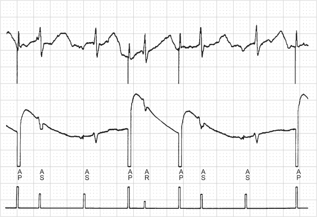
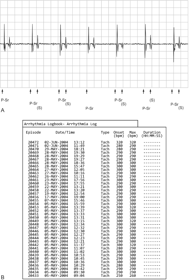
Fig. 10.35 Refractory. (A) Programmer-derived tracing that demonstrates sensor-driven atrial pacing (P-Sr) and intermittent sensed (S) events that follow the sensor-driven atrial event. The pacemaker was programmed AAIR at a rate of 75 ppm; atrial refractory period of 280 ms. (B) The arrhythmia logbook had recorded very frequent atrial tachycardias. Although this represents far-field sensing, the far-field events fall within the programmed ARP and therefore do not alter the pacing rate. However, for purposes of tachycardia detection they are counted and the double counting results in the arrhythmia logbook recording this as a tachycardia.
Oversensing can be caused by many things, which can be classified as:
- Biologic sources of interference, e.g., retrograde P wave, T-wave myopotentials
- Paced ventricular afterdepolarization, i.e., sensing the “decay” of the ventricular pacing output
- Nonbiologic sources of electromagnetic interference (see Chapter 12: Electromagnetic Interference).
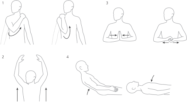
If myopotential inhibition is suspected, a series of maneuvers should be performed in an effort to document the cause (Fig. 10.36). In our pacemaker clinic, a series of isometric maneuvers is accomplished while the electrocardiogram is monitored:
- Hands clasped, pulling against each other
- Palms of hands together, pushing against each other
- Reaching with right arm across left shoulder
- Reaching with left arm across right shoulder
- Pocket manipulation (although not specifically to bring out myopotential inhibition, but instead to assess for integrity of the lead or leads and integrity of the lead–connector block connection, this procedure is carried out in concert with the other maneuvers).
Fig. 10.36 Cartoon depictions of various maneuvers used to provoke interference during troubleshooting a permanent pacemaker. These include: 1. Hands clasped, pulling against each other. 2. Palms of hands together, pushing against each other. 3. Reaching with right arm across left shoulder. 4. Reaching with left arm across right shoulder.
If maneuvers induce myopotential inhibition, the programmed sensitivity is made less sensitive and the maneuvers are repeated in an effort to find a sensitivity value at which significant myopotential inhibition no longer occurs but sensing of intracardiac events is still intact (Fig. 10.37).
Fig. 10.37 Series of electrocardiographic tracings obtained during provocative maneuvers to induce myopotential inhibition in a patient with a pacemaker programmed to the VVI mode. There is significant inhibition at programming to 1 mV (A) sensitivity. Inhibition decreases at 2.0 mV (B) and is absent at 4.0 mV (C).
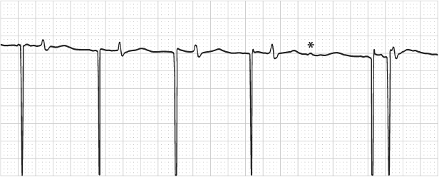
When an interval longer than the programmed lower rate is observed, the point of sensing can be determined by measuring backward from the pacing artifact that terminates the longer interval (Fig. 10.38). For example, if a VVI pacemaker is programmed to 60 ppm, 1000 ms, and an interval of 1500 ms is observed, measuring back 1000 ms from the pacing artifact that ends the 1500-ms interval marks the point of sensing, i.e., the point at which the timing cycle is reset.
Fig. 10.38 Electrocardiographic tracing from a patient with a VVI pacemaker. The programmed rate of the pacemaker is 70 ppm, 857 ms, but there are longer intervals. Measuring 857 ms backward from the ventricular pacing artifact that ends the longer intervals determines that the point of sensing is either a retrograde P wave or a T wave. Without electrograms or a diagnostic interpretation channel, one cannot be certain which event was oversensed.
(From Hayes DL, Zipes DP. Cardiac pacemakers and cardioverter-defibrillators. In Braunwald E, Zipes DP, Libby P, eds. Heart Disease: A Textbook of Cardiovascular Medicine, 6th edn. Philadelphia: WB Saunders Co., by permission of the publisher.)
An incompatible lead-header combination is a clinical possibility, but is rarely seen. Lead design and compatibility are discussed in Chapter 4: Choosing the Device Generator and Leads. Any incompatibility of the lead and header should be readily apparent at the time they are connected. To be certain that an adequate connection has been established at the time of implantation if pacing output is not observed, a magnet should be applied to confirm output and capture and/or device interrogation should be performed and thresholds documented via the programmer.
With international standard 1 (IS-1) lead-header designs, unipolar and bipolar leads are of the same dimensions. If a unipolar IS-1 lead is connected to a bipolar pacemaker that is programmed to a bipolar configuration, no pacing will occur. Most contemporary pacemakers detect the incompatibility and prevent the programming combination, allowing the pacemaker to be programmed only to a unipolar configuration.
Pseudo-malfunctions may also suggest failure to output. Small bipolar pacing artifacts may not be visible on the electrocardiogram and raise the question of failure to output or of oversensing.
Digital recording systems may also give the appearance of failure to output.21 Digital recording systems, the type of electrocardiographic recording system used by most hospitals and offices today, artificially create the pacing artifact (Fig. 10.39). As a function of the system, pacing artifacts may not always be seen. Clues to this abnormality is that the ventricular depolarizations with and without pacing artifacts are of the same morphology. In Fig. 10.40 this pseudo-malfunction is associated with true failure to capture in a patient with exit block. In this situation, another clue is that all the pauses are a multiple of the programmed lower rate.
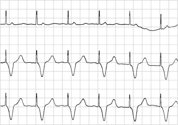
Fig. 10.39 Part of a 12-lead ECG from a patient with a dualchamber pacemaker. The paced QRS morphology is the same for all beats in each of the three channels depicted. However, there is no discernible pacing artifact preceding the third QRS complex. This complex is indeed paced, the patient is completely pacemaker-dependent, but due to the digital recording system, the pacemaker artifacts are not always reliably seen. This may be a source of confusion when interpreting the paced electrocardiogram.
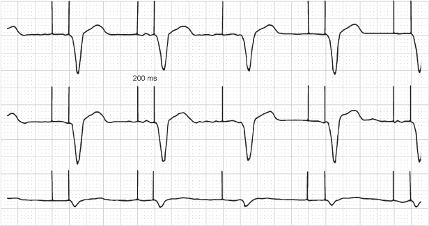
Fig. 10.40 Electrocardiographic tracing from a patient with a pacemaker programmed to the VVIR pacing mode. The lower rate of the pacemaker is programmed to 60 ppm. The tracing was obtained urgently in the emergency department and demonstrates intermittent failure to capture and a long pause without evidence of pacing artifacts, a suggestion of oversensing (pacemaker telemetry was not available at the time). Careful inspection of the second ventricular depolarization reveals the lack of a pacing artifact. This patient was pacemaker-dependent, and all ventricular activity was paced. Pacing artifacts occur during the interval that appears to be a pause without any pacing activity. This finding was proven by intracardiac electrograms. It can also be suspected from the surface electrocardiogram, because the pause is an even multiple of the programmed lower rate interval. If this were oversensing, a pause that was an exact multiple of the pacing rate would be unlikely. The inability to detect pacing artifacts is not uncommon with digital recording systems.
Ventricular avoidance pacing algorithms are designed to allow the patient’s intrinsic ventricular conduction to dominate and minimize ventricular pacing. Multiple algorithms are available to achieve this outcome (see Chapter 8: Programming). With some algorithms the ventricular output may be inhibited in an attempt to allow intrinsic conduction to occur. This may give the appearance of intermittent failure to output and may be misinterpreted as pacemaker malfunction if the programmed settings are not known (Figs 10.41 and 10.42).
Fig. 10.41 A 12-lead ECG where there is a single episode of ventricular failure to output after a paced atrial event. This is an example of Managed Ventricular Pacing (MVP), a ventricular pacing avoidance algorithm. The pacemaker performs periodic one-cycle checks for AV conduction and the opportunity to resume AAIR or AAI therapy.
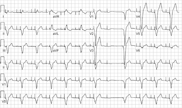
Fig. 10.42 Three-channel recording from an ambulatory monitor. The tracing begins with atrial pacing and intrinsic ventricular conduction with a narrow-complex QRS. This is followed by atrial pacing and capture and no subsequent ventricular pacing output. The next event seen is an atrial pacing artifact that occurs immediately before a wide-complex QRS escape. (The atrial artifact gives the appearance of a pseudo-pseudo-fusion event.) The initial wide-complex event is followed by another atrial pacing artifact and yet another which is immediately followed by another wide-QRS escape complex. The last two RR cycles occur at a shorter cycle length and there is presumed AV nodal conduction from the atrial paced artifacts, but with a continued wide QRS morphology. This is an example of managed ventricular pacing (MVP), one of the ventricular pacing avoidance algorithms. With this algorithm, if two of the four most recent nonrefractory A-A intervals are missing a ventricular event, the pacemaker will identify this as a persistent loss of AV conduction and switch to the DDDR or DDD mode. However, in this example, there are only single A-A intervals missing a ventricular event, so the switch to DDD mode does not occur. This is normal function.
Although not a pseudo-malfunction, a possible error of interpretation may be due to failure to recognize a near-isoelectric P or R wave on a surface ECG lead. If an event is truly isoelectric, an intracardiac electrogram or a diagnostic interpretation channel is necessary to make the diagnosis. Figures 10.43–10.45 show examples of near-isoelectric events. A basic tenet to remember in troubleshooting is that even without a recognizable depolarization, a subsequent repolarization, i.e., a T wave, affirms a preceding depolarization.
Fig. 10.43 Three-channel recording from a patient with a DDD pacemaker. The top tracing would suggest oversensing with failure to output unless the other ECG leads were available for comparison. The tracing also demonstrates varying degrees of fusion beats.
(Tracing courtesy of Dr. Seymour Furman.)
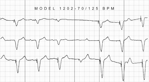
Fig. 10.44 Electrocardiographic tracing from a patient with a VVI pacemaker. (Marker notations have been added to assist in interpretation of the tracing.) After the third ventricular event which is an intrinsic event (VS), there appears to be some baseline activity but no clear-cut cardiac activity. However, measuring backward from the subsequent paced ventricular event by the interval equal to the programmed pacing rate appears to indicate that the activity in the baseline is two intrinsic ventricular events and T waves.
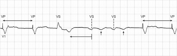
Fig. 10.45 Transtelephonic tracing from a patient with a dual-chamber pacemaker. Measuring back from the final ventricular paced event by an interval equal to the AA interval shows that a small-amplitude complex representing an intrinsic ventricular event is present, noted by (*). (The AA interval is used for measurement because only one paced ventricular event occurs. If there is no alteration of the AV or AR interval, the AA interval should generally be equivalent to the VV interval.)
Undersensing
- Change in intrinsic complex, e.g., bundle branch block, ventricular fibrillation, ventricular tachycardia, AF
- Myocardial infarction
- Lead dislodgment or poor positioning (Figs 10.46–10.48)
- Lead insulation failure
- Magnet application
- Battery depletion
- Pulse generator component failure or header abnormality (Fig. 10.49)
- Metabolic or drug effect
- Functional undersensing.
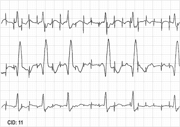
Fig. 10.46 Tracing from an ambulatory monitor shows intermittent atrial failure to sense. This is best seen at the fifth ventricular complex. A P wave precedes the intrinsic ventricular event, but this is not sensed, and an atrial pacing artifact occurs immediately before the intrinsic ventricular complex. The ventricular complex is sensed in the crosstalk sensing window. As a result, the ventricular pacing artifact is delivered early after the intrinsic ventricular event, i.e., ventricular safety pacing.
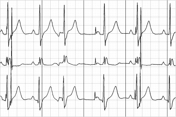
Fig. 10.47 Telemetry with surface electrocardiogram, top; atrial electrogram, middle; and ventricular electrogram, bottom. Markers are present on the ventricular channel. There are six ventricular events but only three with “marker” annotation. The first ventricular event is not sensed and not annotated. The second ventricular event is labeled as a paced ventricular (V) event; the third is an intrinsic ventricular event (R); the fourth is not sensed and is followed approximately 360 ms later by a paced ventricular event (V); and the final event is not sensed.
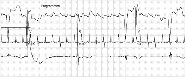
Fig. 10.48 Two-channel rhythm strip from a patient with a pacemaker programmed to the VVI mode with AutoCapture. There is intermittent ventricular undersensing. The (*) note ventricular events that are not sensed and followed by a pacing artifact. Because there is failure to capture, albeit functional failure to capture, the AutoCapture mechanism follows this with a second pacing artifact delivered at higher output. On one occasion the second output is distant enough from the intrinsic ventricular depolarization that the myocardium is no longer refractory and paced depolarization occurs. On the others (arrowhead) there is functional failure to capture on the second output because the myocardium is still refractory.
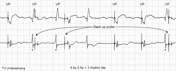
Fig. 10.49 (A) Electrocardiographic tracing from a patient with a dual-chamber pacemaker and intermittent atrial failure to sense. Despite reprogramming, the intermittent atrial undersensing persisted. (B) Side view of pulse generator and (C) top view. At the time of pulse generator replacement, inspection revealed an area of corrosion at the site of one of the atrial grommets. (D) After pulse generator replacement, no further atrial undersensing was noted. Normal P-wave tracking is noted in this tracing.
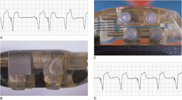
A clinical approach to assessment of the most common causes of undersensing is detailed in Table 10.6.
Table 10.6 Failure to sense.
|
Any event that results in an intrinsic complex that differs from the intrinsic complex that was present and measured at the time of pacemaker implantation may cause undersensing. For example, a premature ventricular contraction, which may actually appear larger than the normally conducted ventricular event on the surface electrocardiogram, may not be sensed (Fig. 10.50). Making the ventricular sensing channel more sensitive may allow normal sensing of premature ventricular contractions. However, if the undersensing is only intermittent, the premature ventricular contractions occur rarely, and the normally conducted beats are appropriately sensed, it may not be necessary to take any additional action.
Fig. 10.50 Electrocardiographic tracing in which a single premature ventricular contraction is not sensed.
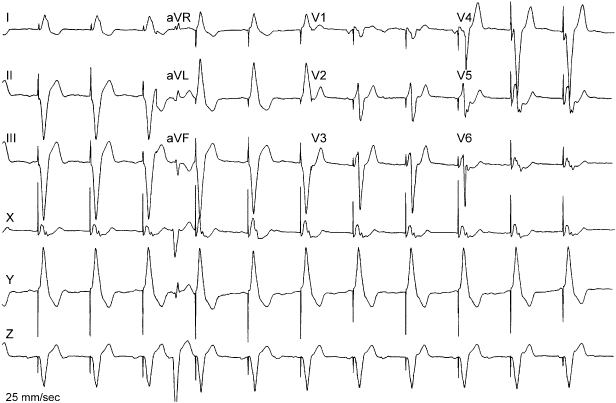
Undersensing in either chamber is theoretically troublesome because of the potential for competitive pacing. Specifically, the concern is one of pacing in a vulnerable portion of the cardiac cycle, i.e., during repolarization. Pacing on a T wave could initiate ventricular fibrillation or ventricular tachycardia, and pacing during atrial repolarization could initiate AF. Both have been documented, but both are uncommon. This conclusion is supported by the fact that although magnet application results in competitive pacing, as a routine part of transtelephonic follow-up it is rarely identified as inducing a tachyarrhythmia.
As noted above, any event that damages the myocardium at the electrode–myocardial interface could alter sensing thresholds. Undersensing may be a manifestation of conductor coil fracture and insulation break. In fact, sensing abnormalities are the most common electrocardiographic manifestation of loss of insulation integrity.
Also noted previously, metabolic disturbances and drugs can affect sensing thresholds. Class IC antiarrhythmic agents are the most likely to alter sensing thresholds, and hyperkalemia is the most common metabolic disturbance to result in undersensing.
Sensing may not be reliable when pacemaker battery reaches a very low voltage level.
As noted below, the first programming step used to correct undersensing is often to make the sensing channel more sensitive, i.e., a smaller number, although uncommon exceptions occur.
Functional undersensing occurs when an intrinsic event falls within a blanking period or refractory period and is not sensed as a function of the pacemaker programming. This can cause confusion in electrocardiographic interpretation unless electrograms or a marker channel is available. Figure 10.21 demonstrates functional undersensing as a result of extension of the post-ventricular atrial refractory period (PVARP). Because the PVARP is extended in consecutive cycles, the P waves are consecutively within this period and therefore not tracked. The appearance is of true undersensing, but function is normal.
When undersensing occurs (Fig. 10.51), the approach should be as follows:
- Determine the cause of the undersensing
- Assess the amplitude of the undersensed event and compare the measured signal amplitude with the programmed sensitivity
- If possible, correct whatever change has resulted in undersensing
- If the cause of the undersensing cannot be corrected or if immediate resolution is required, reprogram the sensitivity to a more sensitive value.
Fig. 10.51 Electrocardiographic tracing demonstrating VVI pacing with intermittent ventricular failure to sense.
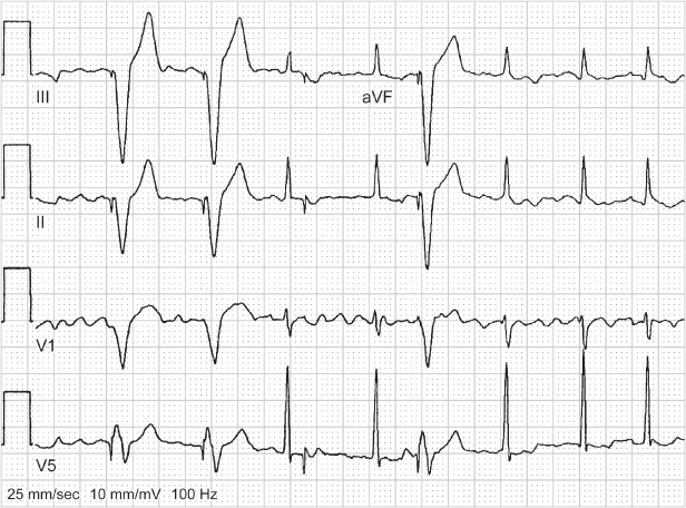
Alteration in Programmed Pacing Rate
- Circuit failure
- Battery failure
- Magnet application
- Hysteresis
- Crosstalk
- Undocumented reprogramming
- Oversensing
- Runaway pacemaker
- Malfunction of electrocardiographic recording equipment; alteration in paper speed.
Undocumented reprogramming is probably the most common cause of an alteration in the programmed pacing rate; i.e., another healthcare professional has reprogrammed the pacing rate and failed to document the change. To avoid this, a system should be in place whereby any reprogramming requires that the pacemaker be interrogated, the programmed values stored and the programming change recorded in the patient’s medical record.
Hysteresis, crosstalk, far-field sensing, and oversensing alter pacing rate, as previously described. If hysteresis is the cause of the altered rate, obviously no action need be taken, because the hysteresis is presumably desirable. If oversensing of any type is causing the altered pacing rate, steps should be taken to correct or remove the source that is being oversensed (see earlier).
Circuit or component failure could alter the programmed rate in an unpredictable fashion. Runaway pacemaker is a manifestation of a component failure or a software-based programming error that results in pacing at dangerously fast rates, in excess of 1000 ppm. It is most likely to occur if a pacemaker is in the field of therapeutic radiation.23,24 Therapeutic radiation can cause failure of the complementary oxide semiconductor. The failure is unpredictable by both time of exposure and total radiation. Runaway pacemaker constitutes an emergency. If the patient is hemodynamically compromised, the pacemaker must be urgently disconnected. If time allows, the pacing lead can be properly released from the pacemaker. If hemodynamic failure does not allow the extra time required to properly release the lead, the lead should be transected and temporary pacing should be available if necessary.
Confusion may arise if there is malfunction of the electrocardiographic recording equipment; e.g., the paper sticks or the speed is not constant. This defect can give the appearance that the pacing rate is different from the programmed rate or erratic. The clinical approach to an alteration in pacing rate depends entirely on the cause.
New Symptoms after Pacemaker Implantation
As initially discussed, some of the most frequently encountered new complaints after pacemaker placement are recurrent syncope or presyncope, fatigue, and palpitations. Several pacemaker-specific causes should be considered in the paced patient complaining of these symptoms.
- Pacemaker syndrome
- Failure to capture
- Reversion to backup mode
- Inappropriate programmed rate or sensor
- Symptomatic upper rate response
- Primary myocardial abnormality or ventricular rhythm disturbance.
Pacemaker syndrome should be suspected if the paced patient complains of general malaise and fatigue. This diagnosis is discussed in Chapter 2: Hemodynamics of Cardiac Pacing. Symptoms include the following:
- General malaise and fatigue
- Chest discomfort
- Cough
- Symptomatic cannon A waves
- Presyncope or syncope
- Confusion
- Dyspnea on exertion.
As part of the troubleshooting process, blood pressure readings should be obtained with and without pacing if the patient is not pacemaker dependent. Blood pressure differences may be even more dramatic if paced and nonpaced pressures are checked in the supine and upright positions. It must be remembered that pacemaker syndrome can occur with any pacing mode if AV synchrony is uncoupled.
Failure to capture or output may result in relative bradycardia and symptoms compatible with low cardiac output. Failure to restore rate response adequately, i.e., persistent chronotropic incompetence, may also be accompanied by symptoms compatible with low cardiac output.
Exposure of the pacemaker to electromagnetic interference could potentially cause reversion to a backup mode. Because most backup pacing modes are non-rate-responsive and often single-chamber, patients may experience symptoms of pacemaker syndrome or general fatigue, effort intolerance from lack of chronotropic support and loss of AV synchrony.
Palpitations are also frequently reported by paced patients. These may be due to the following:
- Intrinsic tachyarrhythmia
- Ventricular tracking of an atrial tachyarrhythmia
- Pacemaker-mediated tachycardia
- Excessive rate response from a sensor-driven pacemaker
- Search hysteresis.
Before mode switching was available, ventricular tracking of atrial tachyarrhythmias was a frequent source of palpitations. Without mode switching, treatment often required programming the pacemaker to a nontracking mode.
Pacemaker-mediated tachycardia (PMT) may occur when AV synchrony is uncoupled and a ventricular event results in retrograde atrial activation. The retrograde atrial event is sensed on the atrial sensing channel of the pacemaker and initiates the AV interval (AVI). When the AVI times out, a ventricular pacing artifact is delivered. If retrograde conduction is sustained, the patient will have a sudden increase in their paced rate, usually to a rate at or near the programmed maximum tracking rate. The tachyarrhythmia will persist until retrograde atrial activation ends, the retrograde atrial event falls in the post-ventricular refractory period and is not sensed or a PMT termination algorithm is invoked (see Chapter 8: Programming). PMT is most commonly initiated by a premature ventricular event or atrial failure to capture.
A rate-adaptive sensor programmed too aggressively as well as search hysteresis can also cause symptoms (see earlier) as a result of relatively sudden rate alteration. Occasionally, patients who are paced after being chronotropically incompetent for a long period of time may have poor tolerance of the new rate response. Although paced rates may be appropriate, patients may have a sensation of relative tachycardia and complain of palpitations. This may require reprogramming the pacemaker to a less aggressive rate response and allowing the patient to adjust slowly to faster rates. The rate response can then be reprogrammed as tolerated.
As discussed in Chapter 8: Programming, an inappropriately programmed rate-adaptive sensor may result in suboptimal cardiac output, which can be corrected by optimization of sensor settings.
Patients who have abrupt 2 : 1 AV block at the upper rate limit may have symptoms from the sudden change in ventricular rate. Although this is much less common at present given the fact that most patients are programmed to a rate-adaptive mode, 2 : 1 AV block upper rate response may lead to symptoms, and caregivers need to understand the phenomenon. A sudden decrease in heart rate obviously affects cardiac output (cardiac output = heart rate × stroke volume). If this upper rate behavior is recognized as the cause of the patient’s symptoms, reprogramming the pacemaker may alleviate the problem. Programming changes include the following:
- Shortening the total atrial refractory period to allow a higher achievable upper rate limit
- Shortening the PVARP
- Programming “on” rate-adaptive PVARP
- Programming “on” rate-adaptive AV delay
- Programming “on” or optimizing sensor-driven pacing, or both
- Programming “on” another feature, such as rate smoothing or fallback, to minimize sudden changes in cycle length.
Primary cardiac abnormalities may also result in suboptimal cardiac output. Development of a primary cardiomyopathic process, left ventricular dysfunction due to ischemic disease or tachyarrhythmias may be manifested by symptoms compatible with low cardiac output.
The number and versatility of current pulse generators and lead systems available challenge the caregiver to understand all the various devices and their features when assessing a system for potential malfunction. A thorough understanding of pacemaker timing cycles and electrocardiography (Chapter 7: Timing Cycles), pacemaker radiography (Chapter 11: Radiography of Implantable Devices), and programming (Chapter 8: Programming) is critical for successful troubleshooting. An understanding of the clinical situation, a systematic approach to troubleshooting, assessment of pacing system integrity, and judicious use of manufacturers’ technical support teams can help distinguish between malfunction and apparent malfunction.
ICD Troubleshooting
ICDs are susceptible to all types of troubles that pacemakers can experience, as well as troubles specific to high-voltage, antitachycardia devices. These troubles can be minimized by attention to intraoperative technique (Chapter 5: Implanting and Extracting Cardiac Devices), thoughtful perioperative programming (Chapter 8: Programming), and analysis of in-office or remote follow-up data (Chapter 13: Follow-up). The primary ICD-specific problems that require troubleshooting include shocks, ineffective antitachycardia therapy, and failure to deliver antitachycardia therapy. This section reviews the diagnostic tools of ICD troubleshooting and addresses these three specific problems, emphasizing the response to shocks, the most common troubleshooting problem. Additionally, we consider the differential diagnosis of ICD lead failures presenting with abnormal lead diagnostics and/or inappropriate shocks.
Diagnostic Tools for ICD Troubleshooting
History, Physical, and Basic Laboratory Data
Device-Focused History and Physical:
Key elements include the following:
Findings Pertinent to Presentation with Shocks:
These include patient activity at the time of shock, symptoms preceding the shock, and spatial or temporal patterns of shocks.
Patient Activity:
Multiple shocks during vigorous exercise suggest inappropriate therapy for sinus tachycardia or rapidly conducted AF if the integrity of lead system is verified. Stretching may provoke oversensing due to a lead insulation defect or conductor fracture. Pectoral muscle exercise may result in oversensing if an insulation defect is present in the pocket. Deep breathing, straining, or sitting up provoke in oversensing of diaphragmatic myopotentials.
Symptoms:
Rapid palpitations preceding a shock suggest that the shock was delivered in response to a true arrhythmia (either SVT or VT), but does not exclude oversensing. The patient may experience palpitations due to ATP delivered in response to oversensing. Preceding syncope occurs in only a minority of shocks.29 It may be caused by true VT/VF resulting in hemodynamic collapse; but, in pacemaker-dependent patients, oversensing may cause inhibition of pacing and profound bradycardia while the ICD is detecting VF and charging. However, because most VT/VF episodes are not preceded by symptoms,30 absence of symptoms does not indicate absence of VT/VF.
Shocks Patterns:
Recurrence of shocks in the same physical environmental may indicate inappropriate shocks due to external electromagnetic interference (EMI). In most studies, the first shock success rate for termination of true VT/VF is 80–90%.31 Thus most clinical episodes of true VT/VF are terminated by one or two shocks. In contrast, repetitive shocks within seconds suggests inappropriate shocks in response to sensed events that are not terminated by the shock (e.g. sinus tachycardia, or oversensing of rapid physiologic or nonphysiologic signals). In previous reports, shocks for causes other than VT/VF occurred in clusters of 4.0 ± 2.0 per episode, compared with 1.6 ± 0.9 shocks per episode for true VT/VF.32,33
Phantom Shocks:
Some patients report experiencing “shocks” in the absence of shock delivery by the ICD.34 This may occur either in patients with previous ICD shocks as a symptom of anxiety or in patients who have never experienced an actual ICD shock as “little shock.”
Radiography
System radiography is discussed in Chapter 11: Radiography of Implantable Devices, and briefly in Chapter 13: Follow-up. It is particularly helpful in identifying lead positions, lead dislodgments, the relationship between defibrillation shock vectors and the mass of LV myocardium, specific lead and connection failure modes. Intraoperative radiography and cine fluoroscopy may be useful adjuncts in specific troubleshooting problems, as discussed below.
ICD Diagnostics
ICDs include all diagnostics present in pacemakers, including indicators of battery status, automatic measurement of P and R waves, and automated measurement of pacing impedance. They store the programmed parameters described in Chapter 8: Programming, which are vital to interpreting ICD function. In addition, they include ICD-specific diagnostics. The most commonly used diagnostics relate to classification of device-detected arrhythmia episodes, the high-voltage system, and specific metrics of oversensing common in ICDs. In addition to electrograms (EGMs), ICDs store specific data relating to device-detected arrhythmia episodes that satisfy the rate and duration criteria for VT/VF detection (or monitor zones), including the specific criteria used to classify the rhythm as VT or SVT and the ICD’s interpretation of the success or failure of delivered therapy. Some dual-chamber and cardiac resynchronization ICDs also store data regarding the duration and ventricular rate of AF episodes that do not satisfy ventricular rate criteria. Diagnostics specific to the high-voltage system include shock lead impedance, charge time for the high-voltage capacitors, and measured delivered energy for each delivered shock therapy. These are discussed in relation to diagnosis of high-voltage lead problems (see High-voltage conductor failures, below) and evaluating ineffective therapy (see ICD system-related factors, below). Some ICDs include specific oversensing diagnostics intended to facilitate diagnosis of T-wave oversensing or lead and connection problems. ICDs also diagnostics also indicate the cause of any auditory or vibratory patient alert.
Analysis of ICD Electrograms and Marker Channels
Electrogram Sources
Analysis of ICD electrograms and marker channels is the cornerstone of troubleshooting the response to sensed events and detected tachycardias. ICDs store two or more electrograms recorded between various implanted electrodes. Typically, one or more source electrograms are programmable (Fig. 10.52). Two primary electrograms are available in most modern ICDs: the ventricular sensing (near-field) electrogram recorded between lead tip electrode and the adjacent ring or coil and the shocking electrogram recorded between or among two or three high-voltage electrodes. Other useful electrograms available in some ICDs include the leadless ECG recorded between the can and SVC coil on dual-coil defibrillation leads,35 the atrial bipolar sensing electrogram in dual-chamber or cardiac resynchronization ICDs, and the LV electrogram in cardiac resynchronization ICDs.
Fig. 10.52 ICD leads and electrograms. The left panel shows an ICD system including left-pectoral active can and RV lead. Right panel shows telemetered electrograms. The dual-coil lead uses true-bipolar sensing between tip and ring electrodes. Right panel shows telemetered high-voltage (shock), far-field (FF-VEGM) and sensing, near-field (NF-VEGM) electrograms with annotated markers. Arrows on marker channel denote timing of R waves sensed from true-bipolar electrogram. ICDs measure all timing intervals from this electrogram and display them on the marker channel, which also indicates the ICD’s classification of each atrial and ventricular event by letter symbols. In this figure, VS indicates sensed ventricular events in the sinus rate zone and numbers indicate RR intervals. The stored near-field, rate-sensing electrogram is a wide-band (unfiltered) signal in Medtronic ICDs, but filtered in Boston Scientific and St. Jude ICDs.
(From Friedman PA, Swerdlow CD, Hayes DL. Troubleshooting. In: Hayes DL, Friedman PA, eds. Cardiac Pacing and Defibrillation: A Clinical Approach, 2nd edn. West Sussex, UK: Wiley-Blackwell, 2008: 401–516, by permission of Friedman, Swerdlow, and Hayes.)
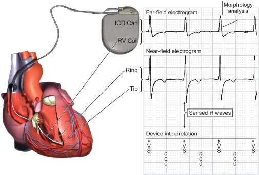
The ICD determines the timing of each atrial and ventricular sensed event from the corresponding sensing channel. The timing of these events as sensed by the ICD’s circuitry is displayed on the corresponding marker channel. In addition to displaying the interval between sensed events, the marker channel provides information about the timing of sensed events in relation to programmed detection intervals and intervals of the pacemaker timing cycle. ICD detection algorithms make most decisions by analysis of the atrial and ventricular intervals displayed on the marker channel. The most common analysis performed on the far-field channel is analysis of ventricular electrogram morphology. The closely spaced, near-field electrogram usually provides a sharp, short, local signal for timing that does not exceed the short ventricular blanking period. However, its small field of view limits information about global ventricular electrogram morphology. A modeling study reported that the fraction of ventricular myocardium recorded by the true-bipolar, integrated-bipolar, and far-field electrograms as 3–7%, 20–35%, and 50–70%, respectively.36 An important limitation of near-field signals is that electrogram morphology in VT may be indistinguishable from that during sinus rhythm in at least 5–10% of VTs (Fig. 10.53).37,38
Stay updated, free articles. Join our Telegram channel

Full access? Get Clinical Tree


