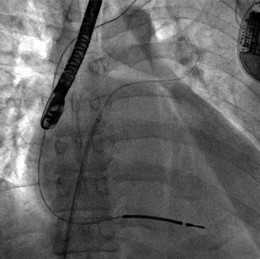
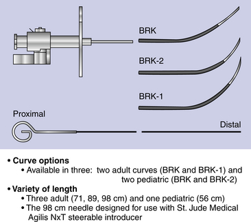
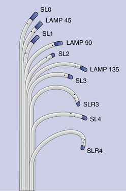
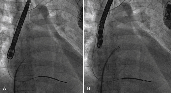
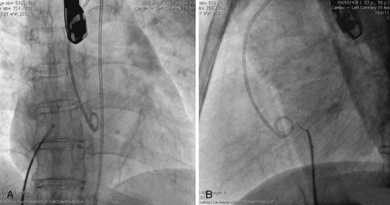
Chapter 4 The transseptal puncture has been in use since its description in 1959 by Drs. Ross, Braunwald and Morrow.1 Until recently, transseptal puncture has been used relatively rarely, primarily for diagnostic purposes and percutaneous balloon mitral valvuloplasty (PBMV). In recent years, with the advent of complex structural heart interventions and electrophysiology ablation procedures, the use of transseptal puncture has increased.2–4 In the arena of structural heart disease interventions, transseptal puncture is often a crucial initial part of the procedure. These procedures include PBMV, closure of the long-tunnel patent foramen ovale (PFO), atrial septostomy, left atrial appendage occlusion, percutaneous mitral valve repair (e.g., with MitraClip [Abbott Vascular Structural Heart, Menlo Park, Calif.]), mitral paravalvular leak closure, and many investigational mitral repair or replacement technologies. The transseptal puncture can be performed safely using standard equipment. This may include a Mullins sheath and dilator and a Brockenbrough needle (Medtronic, Santa Rosa, Calif.) (Figure 4–1). However, there are more options available currently and operators may choose to use other commercially available needles and sheaths/dilators. These include the BRK series of transseptal needles and the SL series of transseptal sheaths (St. Jude Medical, St. Paul, Minn.) (Figures 4–2 and 4–3). Specific equipment for PBMV may also be used off-label. These include the “curly” left atrial guidewire (TORAYGUIDE Guidewire; Toray Industries, United States), which provides stable support in the LA. Figure 4–1 Components of a transseptal puncture system. Top to bottom: Mullins sheath, dilator, and transseptal needle. Figure 4–2 Some types of transseptal needles and catheters. (Courtesy of St. Jude Medical, St. Paul, Minn.) Figure 4–3 Different transseptal catheters are available with different curves and tip shapes. These are generally available in both 8F and 8.5F sizes. (Courtesy of St. Jude Medical, St. Paul, Minn.) Transseptal puncture under fluoroscopic guidance is usually performed for PBMV and other procedures in which precise location of the transseptal puncture is not crucial. Various methods have been described. The availability of advanced imaging technologies such as transesophageal echocardiography (TEE) and intracardiac echocardiography (ICE) have made the use of fluoroscopic maneuvers (including right atrial angiography) less common. Nonetheless, because PBMV is more commonly performed in developing countries, in which cost considerations of using these technologies may be important, it is important to understand the various techniques available using fluoroscopy to obtain a successful puncture. A transseptal puncture begins with access into the right femoral venous system. Although transseptal puncture is possible from the left femoral vein, the angulation is generally not favorable and therefore avoided if possible. A 0.032-inch guidewire is advanced from the inferior vena cava (IVC) into the superior vena cava (SVC), and the right femoral venous sheath is exchanged for a transseptal sheath and dilator (e.g., Mullins sheath or SL-0 catheter). The transseptal sheath is advanced into the SVC. Operators may, at the same time, choose to place a pigtail catheter in the ascending aorta to demarcate the position of the aorta on fluoroscopy (Figure 4–4). This helps identify the aorta so that the operator may direct the transseptal needle away from it (appreciable primarily in the lateral fluoroscopic projection). In the meantime, the transseptal needle is flushed carefully and attached to a pressure transducer. Many operators will slowly continuously flush the needle with a saline infusion drip to prevent air from entering the system. The small saline flush that emanates from the tip of the sheath can also aid visualization if echocardiographic imaging is used. The needle is then advanced to the distal edge of the transseptal sheath, with the operator taking care to ensure that at least a distance of 1 cm is present between the needle and sheath tips. To do so, the needle is prevented from advancing forward by gripping it in the palm of the right hand while the thumb and index fingers hold the sheath and dilator system (Figure 4–5). The orientation of the needle and sheath must be maintained by matching the metal arrow on the needle’s hub to the direction of sheath’s sidearm (Figure 4–6). The operator ensures that that the needle does not slip forward inadvertently. The entire system of sheath, dilator, and needle is held as one unit and then gradually brought down to the level of the interatrial septum. This technique also maintains a constant and safe needle distance from the tip of the dilator. In a patient with normal or near normal anatomy, as the transseptal system is brought caudally (inferiorly), there is a “drop” into the fossa ovalis as the sheath cross the limbus. This is a tactile event and occasionally may also be appreciated on fluoroscopy as well. Figure 4–4 Fluoroscopic appearance of transseptal puncture in anteroposterior (AP) projection. Figure 4–5 Technique for holding the transseptal system. Figure 4–6 The transseptal sheath and needle are moved as one system by rotating the hand. The arrow on the transseptal needle should be aligned with the sidearm of the sheath, which is oriented toward the curve of the transseptal sheath (arrows). A and B show the system in the horizontal (3 o’clock) position. C and D show the system in the 4 o’clock position (arrows), which is the preferred angle of crossing for the majority of structurally normal hearts. Note that this angle will change with RA or LA enlargement. At this point, the operator may puncture the septum by advancing the needle carefully out the end of the sheath (Figure 4–7). By applying gentle forward pressure to the needle and transseptal sheath, the needle should cross in the LA easily. In some cases, as forward pressure is applied, the needle may slide cranially, and the original puncture location may be lost. In this case, it may be necessary to remove and reshape the needle to gain more purchase on the interatrial septum. In addition, the wire mandril that comes with the Brockenbrough needle can also be used to “anchor” the needle into the septum and to assist in stabilizing the system as forward pressure is applied (Figure 4–8). As the needle crosses in the LA, the pressure transducer should show a left atrial pressure waveform. Importantly, the operator would hope not to see aortic pressure waveforms, which would indicate puncture of the aorta. The operator may also confirm that the needle is in the LA by aspirating blood backwards. Bright red blood will usually indicate that the needle is in the LA if pressure waveforms are consistent as well. An important cautionary note is to avoid flushing the catheter if it appears that the needle has crossed but there is no waveform or if the waveform is dampened. This may represent a thrombus on the needle/catheter system. Flushing into the LA may result in a stroke. Gentle aspiration to remove the thrombus may help. Lack of any pressure may also indicate that the tip of the needle is in the wall of the LA, pericardial space, or other soft-tissue structure. If there is uncertainty as to the location of the needle, the transseptal sheath should never be advanced forward, and the entire system should be withdrawn into the right atrium (RA). There are times in which the needle appears to be clearly into the LA but there is no pressure waveform. This may occur especially if there is a very floppy septum or if an interatrial septal aneurysm is present. In such situations, although it may appear that the needle is very far into the LA on fluoroscopy, it may not have crossed the floppy septum. Adequate preprocedure echocardiography would be useful to identify the presence of a floppy septum or interatrial septal aneurysm. TEE guidance in such situations would be reassuring and would enhance patient safety. Figure 4–7 Needle advancement. Figure 4–8 Use of microwire mandril to assist in transseptal puncture. Once across the interatrial septum, the needle is often directed posteriorly so a slight counterclockwise rotation will direct the needle away from the left atrial posterior wall. The dilator and sheath are carefully advanced over the needle and then just the sheath over the dilator to ensure that the sheath is well in the LA (Figure 4–9). The dilator and needle are then removed, and the sheath aspirated and flushed carefully. If there is difficulty aspirating, the operator needs to consider the presence of thrombus or that the sheath tip is impinging on the wall of the LA. In the latter case, the sheath may be rotated either clockwise or counterclockwise to turn the sheath posteriorly or anteriorly away from the LA wall. Figure 4–9 A shows the transseptal needle at the interatrial septum. B shows that the puncture has occurred and now the sheath is across the septum. The dilator and needle have been withdrawn back into the sheath. Depending on the procedure, a 0.035-inch stiff wire (e.g., Amplatz Super Stiff wire [St. Jude Medical, St. Paul, Minn.]) can be advanced to the LUPV and used as a rail for the delivery for equipment or devices (Figure 4–10). On occasion, a 6F or 7F multipurpose catheter may be used through the transseptal sheath to help guide the positioning of the wire in the LUPV. Some operators recommend the use of the “septal flush” or “stain” to demarcate the interatrial septum.5 This may be done in conjunction with other fluoroscopic transseptal techniques. It is performed by injecting contrast against the interatrial septum. In the lateral projection, a vertical stain suggests dissection of the high septum. With tenting of the interatrial septum at the fossa ovalis, a triangular “tent” of contrast may be seen. These techniques are used when echocardiographic imaging may not be easily available. Before the advent of TEE and ICE, fluoroscopic landmarks were exclusively used in performing a transseptal puncture. These include the use of right atrial angiography, drawing imaginary lines on fluoroscopy stop-frame images, using a pigtail catheter on the ascending aorta, and recognizing the relative positions of the tricuspid valve, coronary sinus, and aorta. Amongst the key points to note is that it is important to avoid the aorta, which is an anterior structure (Figure 4–11). The pigtail catheter helps the operator avoid the aorta. A lateral projection can also help to identify the anterior/posterior direction of the transseptal needle. These techniques remain helpful, especially if imaging is not available. However, for complex structural heart interventions such as the MitraClip and atrial septostomy, or in patients who are at very high risk for transseptal complications (such as prior mitral valve surgery with atrial septal repair), the authors believe that it is essential to have imaging with either TEE or ICE. Fluoroscopy alone would be potentially risky in patients who cannot tolerate any hemodynamic embarrassment. Fluoroscopy would also be unable to determine a precise anatomic puncture site. Of note, electrophysiologists have used additional landmarking tools for transseptal punctures. These include the use of a catheter in the coronary sinus, which delineates the margin of the left atrial free wall; and a catheter at the bundle of HIS to identify the anterior aspect of the interatrial septum. Numerous techniques for transseptal puncture using fluoroscopy alone have been well described in the literature and will not be the focus of this chapter. Figure 4–11 A shows the pigtail catheter in the ascending aorta with the transseptal needle/sheath at the interatrial septum, anteroposterior view. The needle is pointing in the right direction (assuming the patient has normal anatomy). B, Lateral view shows the pigtail anterior to the transseptal needle. The needle is pointing slightly too anteriorly.
Transseptal Heart Catheterization
4.1 Importance of Transseptal Puncture
4.2 Equipment

Transseptal Heart Catheterization Under Fluoroscopic Guidance
“Drop” into the Fossa Ovalis
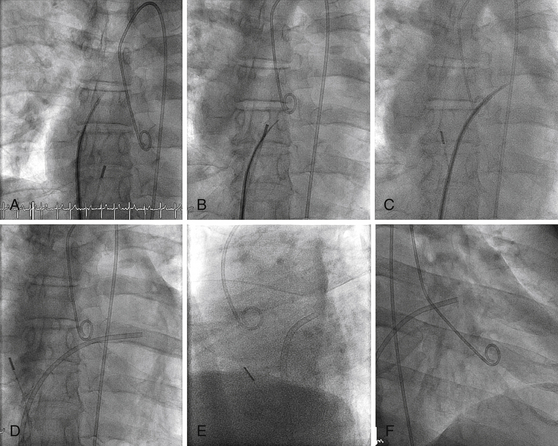
A, Pigtail in aortic root, transseptal sheath in SVC. ICE catheter in RA. B, Transseptal sheath pulled back to RA, fossa engaged, and needle advanced. C, Transseptal sheath and dilator advanced over needle into LA. D, Dilator and needle withdrawn, sheath in LA. E, Lateral view showing transseptal sheath crossing posterior to aorta. F, Right anterior oblique (RAO) projection showing LA sheath and pigtail in left ventricle (LV).
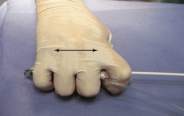
The entire system is grasped within the hand to allow the system to move as one unit. The sheath and dilator and are grasped with the index finger and thumb, and the needle is grasped with the remaining fingers. This ensures a constant relationship between the needle and sheath (two-headed arrow), and avoids inadvertent needle advancement.
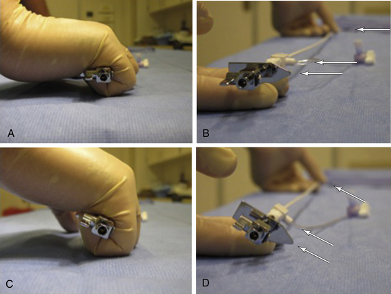
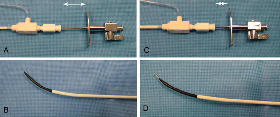
A and B illustrate the relationship of the needle hub to the dilator when the needle is within the transseptal sheath dilator (arrows). In C and D, the needle is advanced slightly out of the dilator, and the distance between the needle hub and dilator decreases (arrows).
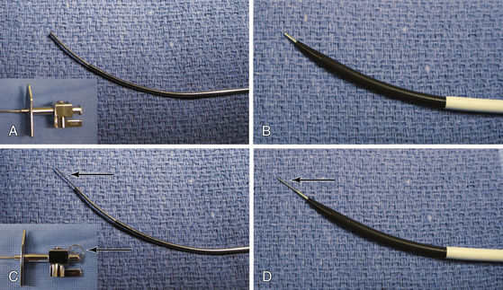
In some cases the needle may slip when forward pressure is applied, and the desired location is not punctured. The wire mandril can be used to “stick” the septum, thereby fixing the needle in one position, and providing stabilization upon needle advancement. A, The needle alone with hub (inset). B, The needle alone protruding from dilator. C, The needle with wire mandril advanced and hub detail (wire mandril shown by arrows). D, The needle and wire mandril advanced out of tip of dilator.
4.3 Septal Flush or Staining Method
Fluoroscopic Landmarks
![]()
Stay updated, free articles. Join our Telegram channel

Full access? Get Clinical Tree


Transseptal Heart Catheterization

