Fig. 15.1
Technique of transseptal puncture. (a) An 8 F 62 cm-long sheath is advanced over a J-tipped guidewire to the superior vena cava. The guidewire is removed and a 71 cm transseptal (TS) needle introduced under continuous flush. (b) With the needle approximately two fingerbreadths (1–2 cm) away from the sheath hub, the entire TS system is positioned at the 4–5 o’clock location and withdrawn caudally until it encounters two leftward jumps: SVC/right atrial junction and muscular interatrial septum. (c) TS tip subsequently engages the fossa ovalis (FO), confirmed by contrast injection. (d) Needle is briskly advanced puncturing the septum. (e) Once needle position is confirmed within the left atrium (LA), the entire system is advanced 1 cm. The dilator is disconnected from the sheath and the needle/dilator is turned toward the 12–1 o’clock location. (f) The sheath is advanced over the dilator into the LA and finally the dilator/needle removed. Passive back bleeding of the sheath de-airs the system and the patient is afterward anticoagulated
The needle is introduced while continuously flushing and is gently advanced through the sheath allowing it to rotate freely within the dilator. If resistance is met, especially at the location of the inferior vena cava/pelvic brim, the needle stylet should be reinserted to prevent piercing through the dilator/sheath. The needle tip must be kept within the lumen of the dilator, maintained approximately two fingerbreadths (1–2 cm) away from the sheath hub. Once the transeptal needle is juxtaposed to the tip of the dilator, the entire system is positioned at the 3–6 o’clock locations – both the sheath with sideport and needle indicator arrow pointed in the same direction. Typically the 4–5 o’clock location (45° from the horizontal plane) is most desired with 3 o’clock being directed toward the patient’s left side (Fig. 15.2). The IAS is a posterior structure typically located at the 4–5 o’clock location; the aorta or retroaortic/transverse sinus is located at the 1–3 o’clock locations and should be avoided.
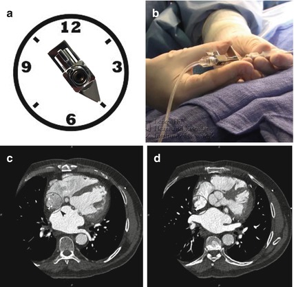
Fig. 15.2
Transseptal needle position. (a) The transseptal (TS) needle indicator arrow dictates the location of the needle tip. With the patient on a horizontal plane (3/9 o’clock), the sheath with sideport and indicator arrow are pointed in the same direction to the 4–5 o’clock location (45° from the horizontal plane). The interatrial septum with the fossa ovalis (FO) is typically a posterior structure located at this position. (b) Holding of the needle and the TS sheath/dilator requires maintaining the same distance from the distal dilator tip (1–2 cm) and concordant movements of the system. (c, d) A clockface superimposed on an axial slice of a cardiac CT reveals the location of the FO at 4–5 o’clock and the aortic valve more anterior at the 1–3 o’clock
Thereafter, the SVC/RA pressure tracing is recorded and the system withdrawn all together toward the IVC, without changing the relative distance between the sheath and needle. Upon descent from the SVC to FO, the system usually encounters two leftward jumps: first at the SVC/RA junction and second from the muscular IAS (in the region of the aortic mound) into the FO. The TS tip should subsequently engage the FO, with the apparatus advanced slightly to firmly contact and tent the septum. A loss of RA pressure is typically noted and 3–5 cc of contrast gently injected to stain the IAS. Once position is confirmed, the sheath/dilator is firmly anchored and the TS needle is briskly advanced, puncturing the septum. The transducer should reveal LA pressure, and additional contrast can be injected and oxygen saturation performed to confirm LA positioning. If LA pressure tracing is not noted, change the scale to assess for aortic pressure. Staining of the pericardium or aorta verifies inadvertent pericardial or aortic puncture. Until confirmation is made, the sheath/dilator should not be advanced.
The entire system is then advanced about 1 cm across the IAS, allowing the dilator to cross the septum. The dilator is disconnected from the sheath, and the needle/dilator is turned in a counterclockwise rotation, toward 12–1 o’clock, bringing the entire system anteriorly toward the center of the LA away from the posterior wall. The dilator/needle is fixed and the sheath advanced into the LA. Successively, the sheath is fixed and the dilator/needle removed slowly to avoid introducing air into the sheath. In addition, aspiration of the TS sheath can introduce air through the valve and is not recommended. Passive back bleeding with the sheath port positioned below cardiac level will allow for appropriate de-airing of the system. The sheath can then be flushed and the patient appropriately anticoagulated to achieve therapeutic ACTs between 250 and 300 ms, further adjusted according to the desired intervention.
15.4 Knowledge of Imaging
15.4.1 Fluoroscopy
Traditionally, TS technique has been performed using fluoroscopy. The anteroposterior (AP) projection allows for identification of appropriate placement within the mid right atrium and against inadvertent placement into the right ventricle or LA through a patent foramen ovale (PFO). The placement of a pigtail catheter into the noncoronary cusp aids at delineation of the posterior border of the aortic wall, as well as the aortic valve/root. It also provides active arterial blood pressure monitoring during the procedure.
In addition to the AP view, other views should be utilized including right anterior oblique (RAO) at 40–50° and left anterior oblique (LAO) at 30–55° [3] (Fig. 15.3). The location of the TS system within the anterior/posterior axis is evaluated in the RAO view and within the superior/inferior axis in the LAO view. In the RAO projection, the IAS is en face with posterior, superior, and inferior borders identified. The intended site of puncture is halfway between the posterior boundary of the atria and a line drawn extending from the posterior aortic wall, approximately 1–3 cm below the noncoronary cusp. The angle at which the septum is punctured can be visualized with the needle directed away from the field of view. In the LAO projection, a line can be drawn extending from the posterior aspect of the pigtail catheter to the spine at a 45° angle. The intended puncture site is located approximately halfway between these two landmarks along this line with the needle directed to the right in a posterior direction.
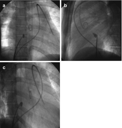
Fig. 15.3
Fluoroscopy for transseptal puncture. (a) In the anteroposterior (AP) view, the pigtail can be noted placed into the noncoronary aortic valve cusp, identifying the posterior border of the aortic wall and aortic root. A balloon-tipped catheter is also visualized within the right ventricular outflow tract into the left branch pulmonary artery. (b) In the left anterior oblique (LAO) view at 30–55°, a line can be drawn from the posterior aspect of the pigtail catheter to the spine at a 45° angle. Intended TS puncture is halfway along this line with the needle directed to the right (posterior). (b) In the right anterior oblique (RAO) view at 40–50°, the intended TS puncture is halfway between the posterior boundary of the atria and a line drawn extending down from the posterior aortic wall, approximately 1–3 cm below the noncoronary cusp
15.4.2 Echocardiography
Nonetheless, distortion of the IAS decreases the efficacy of conventional fluoroscopy in identifying the anatomic landmarks. Echocardiography can offer high-resolution images of important cardiac structures, originally via transthoracic and more recently through transesophageal (TEE) and intracardiac (ICE) echocardiography. 3D TEE enables even more comprehensive imaging of the heart, using either volumetric or multiplane 2D imaging [4, 5]. 3D imaging of the IAS closely parallels true anatomic inspection and is implicitly understood with the image easily rotated from the RA to LA perspective and intracardiac catheters and devices well visualized. Alternatively, ICE provides 2D and now 3D ICE imaging with clear definition of all intracardiac catheters, the IAS, septal tenting prior to puncture, and bubble visualization in the LA confirming needle position [6].
15.5 Advanced Imaging and Site-Specific Puncture
With recent technological improvements, the integration of TEE with fluoroscopy in the catheterization laboratory, also known as echo-fluoro imaging, provides an alternative to traditional image-guided TS catheterization. The basis of fusion imaging relies on the utilization of live echo data and merging it with live fluoroscopy. Echo-fluoro software (Philips Healthcare, Best, Netherlands) automatically registers the 3D TEE field of view, in reference to the probe face plate, with fluoroscopy. After successful registration, a TS landmark can be placed on 2D x-plane and adjusted with confirmation in a 3D view. These landmarks are subsequently overlayed onto fluoroscopy to guide TS puncture (Fig. 15.4).
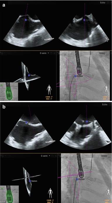


Fig. 15.4
Echo-fluoro imaging. (a) Echo-fluoro imaging provides an alternative to traditional image guidance with live echo data merged with fluoroscopy. Echo-fluoro software (Philips Healthcare, Best, Netherlands) automatically registers the 3D TEE field of view, in reference to the probe face plate, with fluoroscopy. After successful registration, a transseptal (TS) landmark (blue dot) can be placed on 2D x-plane (upper frames) and adjusted with confirmation in a 3D view. These landmarks are subsequently overlayed onto fluoroscopy to guide TS puncture (right lower panel). (b) Successful site-specific TS puncture performed with sheath/dilator advanced into the left atrium at the site of intended position
< div class='tao-gold-member'>
Only gold members can continue reading. Log In or Register to continue
Stay updated, free articles. Join our Telegram channel
Full access? Get Clinical Tree
