3
Transesophageal Echocardiography
Transesophageal echocardiography (TEE) offers the advantage of improved image quality compared to transthoracic images, particularly of posterior structures, such as the pulmonary veins, left atrium (LA), and mitral valve. Image quality is improved both because of the decreased distance between the transducer and the structures of interest and because of the absence of intervening lung or bone tissue. A better signal-to-noise ratio and decreased image depth also allows for the use of higher-frequency (5- and 7-MHz) transducers, which further enhances image quality. Three-dimensional (3D) TEE imaging is increasingly used to evaluate mitral valve and atrial septal anatomy and to guide complex interventional procedures (see Chapter 18).
In this chapter, the TEE procedure and risks are briefly outlined followed by a description of the standard views obtained from each acoustic window (TEE, standard transgastric, transgastric apical, and descending aorta). Sections on the TEE 2D and Doppler evaluation of each cardiac valve and chamber are included to guide the reader to the optimal views for each anatomic structure. This chapter focuses on normal anatomy and flow patterns. Clinical indications for TEE imaging are discussed in Chapter 5, and pathologic images are integrated into subsequent chapters. The use of TEE imaging to monitor surgical and interventional procedures is discussed in Chapter 18.
Protocol and Risks
TEE echocardiography is performed by a physician skilled in both echocardiography and the endoscopy procedure, as detailed in published guidelines for physician training. Typically a cardiac sonographer assists the physician, adjusting instrument settings for optimal image quality and data acquisition. Many physicians use conscious sedation, in addition to local anesthesia of the pharynx, to minimize patient discomfort and improve tolerance of the procedure. When sedation is used, a designated, qualified individual (usually a nurse) monitors and documents the patient’s blood pressure, heart rate, respiratory rate, arterial oxygen saturation, and level of consciousness throughout the procedure. The nurse also ensures patency of the airway and provides suction of oral secretions as needed (see Suggested Reading 4). The specific protocols, medications used for sedation, and monitoring procedures are dictated by the standards of each institution.
TEE echocardiography has a very low incidence of complications when performed by trained individuals with appropriate patient selection and monitoring. However, this procedure does have known risks, which must be taken into consideration in deciding whether the potential information obtained justifies use of this procedure; TEE is contraindicated in some clinical situations as summarized in Table 3-1. The rate of complications serious enough to interrupt the procedure is less than 1% with a reported mortality rate of fewer than 1 in 10,000 patients (Table 3-2). If the preprocedure history or physical examination suggests an increased risk for conscious sedation, appropriate consultation with anesthesiology is essential. If the patient has a history of esophageal disease or symptoms related to impaired swallowing, evaluation of the esophagus or gastroenterology consultation may be needed prior to TEE.
TABLE 3-1
Absolute Contraindications
Uncooperative patient
Severe respiratory depression or tenuous cardio pulmonary status
Recent esophageal or upper GI surgery
Esophageal stricture, mass, or perforation
Active upper GI bleeding
Relative Contraindications
Coagulopathy, thrombocytopenia
Atlantoaxial joint disease or severe cervical arthritis (causing restricted cervical mobility)
Previous esophageal surgery
Esophageal diverticulum or varices
Recent upper GI bleeding
History of dysphasia
Sleep apnea
TABLE 3-2
Risks of Esophageal Intubation
Dental trauma
Esophageal trauma or perforation
Bleeding
Laryngospasm or bronchospasm
Aspiration
Dislodgement of endotracheal tube, especially on probe withdrawal
Displacement of nasogastric tubes
Sore throat, hoarseness
Risks of Conscious Sedation
Hypotension
Respiratory depression (hypoxia, respiratory arrest)
Arrhythmias
Bronchospasm
Death
After sedation and local anesthesia of the pharynx, the probe is gently inserted via a bite block, positioned in the esophagus and advanced as needed to obtain diagnostic images. In intubated patients in the intensive care unit, interventional suite, or operating room, care is needed to avoid compromise of the endotracheal tube position. Indwelling nasogastric or feeding tubes may limit probe motion or result in air between the transducer and the heart, so they often need to be removed for the TEE procedure.
Tomographic Views
The exact views obtained on a TEE study vary depending on the relative positions of the heart, esophagus, and diaphragm in each patient (Fig. 3-1). Even though a multiplane probe allows full rotation of the scan plane, the fixed position of the transducer in the esophagus constrains the possible image planes that can be obtained, potentially resulting in oblique image orientations compared with standard echocardiographic image planes. The goal of TEE study is to perform a systematic and comprehensive examination, using standard short-axis, long-axis, two-chamber, and four-chamber image planes whenever possible. Standard views then are supplemented with additional image planes to demonstrate the specific pathologic processes in each patient. Three-dimensional echocardiographic techniques can facilitate obtaining optimal views and display of spatial relationships, particularly for the atrial septum and mitral valve.
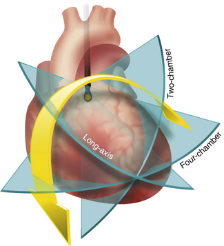
Figure 3–1 TEE image plane rotation.
Rotation of the image plane starting from the four-chamber view (see Fig. 3-3), with the LV apex centered in the image, allows a two-chamber view (see Fig. 3-7) at approximately 60° rotation and a long-axis view (see Fig. 3-9) at approximately 120° rotation. Slight repositioning and angulation of the transducer may be needed as the image plane is rotated to ensure inclusion of the LV apex in the image.
A recommended sequence of images composing a basic complete examination is shown in Table 3-3. The following sections describe views useful for evaluation of the valves and cardiac chambers that are used to supplement the basic examination as determined by the specific clinical question.
TABLE 3-3
Transesophageal Views for Cardiac Valves
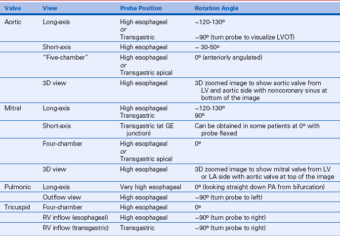
GE, gastroesophageal; LVOT, left ventricular outflow tract; PA, pulmonary artery.
The position of the tip of the probe is described as esophageal or transgastric and is referenced to the cardiac structures seen in each view. The absolute distance of the transducer from the patient’s mouth will vary depending on body size and cardiac position. There also will be variability in the exact degree of rotation, tilt, and angulation needed to obtain the best short-axis, long-axis, two-chamber, and four-chamber views. When standard views are obtained, the images correspond to the anatomy described for the equivalent transthoracic views, with the major difference being image orientation given the TEE transducer position.
For TEE echocardiograms, transducer motions (Fig. 3-2) are referred to as:
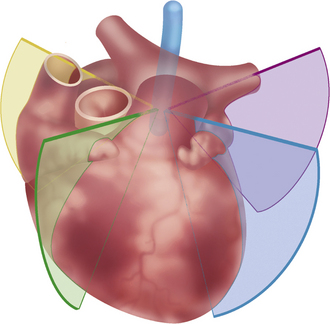
Figure 3–2 Turning the TEE image plane.
From a mid-esophageal position, turning the image plane from left to right provides images of the left pulmonary veins (purple), aorta and LV (blue), RV (green), and RA with superior and inferior vena cavae (yellow).
 Repositioning, defined as movement of the probe up and down in the esophagus,
 Rotation, defined as rotating the image plane from 0° to 180° using the multiplane control knob


Esophageal Position
As the transducer is advanced into the esophagus from the mouth toward the stomach, acoustic access is limited by interposition of the air-filled trachea until the transducer passes the level of the carina. From a high TEE position, with the probe located posterior to the LA, a standard four-chamber view is obtained in the 0° position with angulation of the transducer toward the left ventricular (LV) apex (Fig. 3-3). In the four-chamber view the lateral wall and inferior septal segments of the LV are seen, along with the central portions of both the anterior and posterior leaflets of the mitral valve.
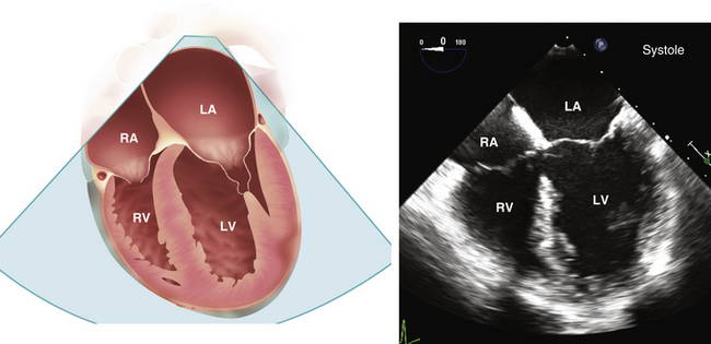
Figure 3–3  TEE four-chamber view.
Drawing (left) and echocardiographic image (right) obtained from a high TEE position with the multiplane probe at 0° rotation. In this view, the apparent apex may actually represent a segment of the anterior wall because of foreshortening of the long axis of the ventricle.
From the four-chamber view, anterior angulation shows the LV outflow tract and aortic valve (the “five-chamber” view) (Figs. 3-4 and 3-5). Posterior angulation provides images of the lateral segments of the mitral valve leaflets, with the coronary sinus visualized on extreme posterior angulation. A 3D image of the mitral valve, viewed from the LA side, obtained by real-time imaging from stored full-volume data acquisition, may be helpful when mitral valve pathology is present.
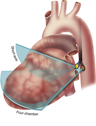
Figure 3–4 TEE probe angulation
From a high esophageal position with the probe at 0° rotation, the transducer tip is extended to obtain a four-chamber view (as shown in Fig. 3-3) or flexed for a short-axis view of the LA appendage (as shown in Fig. 3-8).
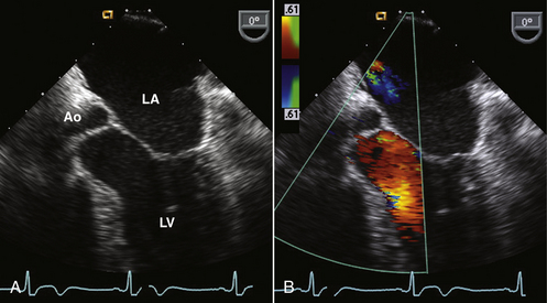
Figure 3–5  LV outflow view.
Slight anterior angulation from the four-chamber view, midway between the image planes shown in Fig. 3-4, allows visualization of the aortic valve and LV outflow tract (A). Color flow shows normal systolic laminar flow in the outflow tract (B).
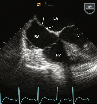
In the standard four-chamber TEE image, the size, shape, and systolic function of the right ventricle (RV) are assessed by turning the probe toward the patient’s right side. This view also provides visualization of the septal and anterior leaflets of the tricuspid valve and the right atrium (RA). The interatrial septum is well visualized with the fossa ovalis and primum septal region clearly identifiable (Fig. 3-6).

Two-Chamber Plane
After ensuring that the LV apex is in the center of the image in a four-chamber view, the image plane is slowly rotated to about 60° to obtain a two-chamber view. Because the apex often is not exactly centered in three dimensions, the position and angulation of the transducer may need adjustment to obtain a two-chamber view that includes the full length of the LV (Fig. 3-7). In this view, the inferior and anterior LV walls of the LV are seen, allowing assessment of regional function and providing the orthogonal plane (along with the four-chamber view) for calculation of ejection fraction. In the two-chamber view, typically only the anterior leaflet of the mitral valve is seen, so it is difficult to evaluate leaflet prolapse in this view.
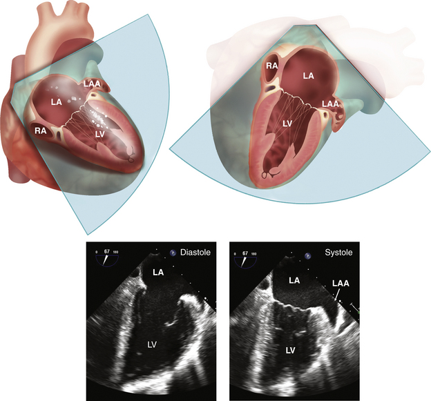
Figure 3–7  TEE two-chamber view.
The two-chamber, or vertical long-axis, plane is shown in the 3D heart and then rotated with the vertex of the sector at the top to correspond to the systolic and diastolic echocardiographic images. This view shows the LA and LV with the LA appendage (LAA), coronary sinus in the atrioventricular groove, and the mitral valve. In the two-chamber view, small portions of the posterior mitral leaflet are seen laterally and medially with the anterior leaflet filling most of the annulus area. Part of a papillary muscle has been shown for orientation, but the papillary muscles are located symmetrically posterior to the image plane.
With further rotation to about 90°, the LA appendage is visualized in a view approximately perpendicular to that obtained in the transverse plane (Fig. 3-8). The left superior pulmonary vein is seen entering the LA by slightly withdrawing and turning the probe laterally.
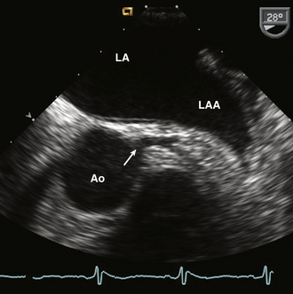
Figure 3–8  Left coronary artery.
LA appendage (LAA) and left main coronary artery seen at a rotation angle of about 30°. Starting in the four-chamber view the probe is slightly withdrawn and angulated anteriorly. Note the normal trabeculation in the LAA compared to the smooth LA wall. This image was obtained with a 7.0-MHz transducer to optimize detection of atrial appendage thrombus.
Long-Axis Plane
From the high-TEE probe position, further rotation of the image plane to about 120° results in a long-axis view of the LV and aorta (Fig. 3-9). Again, slight adjustment of transducer position and angulation may be needed to obtain a view that includes the LV apex. Similar to a transthoracic long-axis view, the proximal ascending aorta, sinuses of Valsalva, and right and noncoronary leaflets of the aortic valve are well visualized. Scanning between this view and the 90° image planes allows appreciation of the perpendicular relationship between aortic and pulmonic valve planes and the slightly more cephalad position of the pulmonic valve. Note that in the esophageal long-axis plane, withdrawing the transducer in the esophagus results in more cephalad images of the ascending aorta with the superior limit of imaging determined by the interposed air-filled bronchus (Fig. 3-10).
Stay updated, free articles. Join our Telegram channel

Full access? Get Clinical Tree


