The Technology of Transcatheter Ablation
Successful transcatheter ablation requires three things. First, a thorough understanding of the arrhythmia being treated—specifically, a precise understanding of the location and physiology of the electrical pathways involved. Second, an understanding of the cardiac anatomy associated with those pathways. Finally, the technology to enable the precise positioning of a catheter and to create the right kind of lesion at a critical location within the pathway. The rapid advance of transcatheter ablation as a therapeutic technique has hinged on steady progression in all three of these requirements.
We will begin by briefly reviewing the technology of lesion generation, and then we will survey the electrophysiology and anatomy of the arrhythmias that have proven amenable to transcatheter ablation.
Direct-Current (DC) Shocks
The use of direct-current (DC) shocks for transcatheter ablation is now mainly of historical interest, as DC energy has been entirely supplanted for this use by radiofrequency (RF) energy. From the first successful ablation in a human in 1982 until approximately 1989, however, DC shocks were the most commonly used energy source for the performance of transcatheter ablation.
To ablate with DC energy, a standard electrode catheter is connected to a conventional defibrillator and a shock is delivered to the distal electrode of the catheter, using a surface electrode as the energy sink. DC shocks delivered in this way generate very high voltages (2000–4000 V) and high currents at the catheter tip. The temperature of the tip electrode instantaneously rises to thousands of degrees Farenheit. The resultant vaporization of blood creates a virtual explosion within the heart, manifested by a rapidly expanding and collapsing incandescent gas globe that generates instantaneous pressures of up to 70 lb/in2 and produces a flash of light and a disquieting popping noise. Thus, transcatheter DC shocks result in several forms of potentially damaging energy—light, heat, pressure, and electrical current. The only “useful” damage created by DC shocks is thought to result from the electrical current; all the other forms of energy tend only to increase the possibility of complications.
The extent of the lesions created by DC energy is related to the amount of energy used. With energies in excess of 250 J, transmural lesions of 2–4 cm2 are common. Unfortunately, the periphery of the lesions created with DC shocks is often patchy—and therefore potentially arrhythmogenic.
Because of the traumatic nature of intracardiac DC shocks and because of the nonideal lesions created, DC energy proved to be of limited utility. Ablation with DC shocks was largely limited to ablation of the His bundle to produce complete heart block. Meanwhile, researchers sought an alternative means of creating intracardiac lesions that would be less dangerous and more effective.
Radiofrequency (RF) Energy
As it turned out, such a means was readily available. RF energy had been used for many years in operating rooms (in the form of Bovie machines) to cauterize small bleeding vessels within the surgical wound. It wasn’t long before electrophysiologists recognized that attaching an RF generator to an electrode catheter would permit the creation of a discrete, well-demarcated intracardiac lesion.
RF energy consists of alternating current (AC) with a frequency range of 100 kHz to 1.5 MHz. In the electrophysiology lab, relatively low frequencies are used in order to avoid the sparking seen with the higher frequencies used in the operating suite. The RF current flow causes localized heating at the tip of the catheter and leads to desiccation and coagulation necrosis of the underlying tissue. The voltage created during RF ablation is relatively low (40–60 V), thus avoiding the barotrauma (i.e. the explosion) seen with DC shocks.
RF generators specifically designed for electrophysiology procedures are now widely available. These RF generators allow instantaneous monitoring of the energy being delivered to the cardiac tissue. The voltage, current, wattage, and impedance can be tracked, permitting the operator to carefully titrate the applied energy. In addition, some ablation systems allow monitoring of the temperature at the catheter tip, thus allowing the operator to more easily avoid coagulation of blood (temperatures in excess of 100 ̊C are associated with formation of a coagulum at the catheter tip, thus dramatically decreasing the energy delivered to the target tissue).
Special catheters have also been developed for use during RF ablation procedures. These come in a variety of shapes and sizes, and allow the operator to apply variable amounts of “bend” to the distal end, in order to facilitate accurate manipulation of the tip of the catheter. Ablation catheters also come equipped with enlarged tip electrodes (usually 4 mm, instead of the “standard” electrode size of 1 mm). The enlarged surface area provides for a more efficient application of RF energy.
RF energy has several advantages over DC shocks. First, RF energy does not produce an explosion. It can thus be applied, in judicious amounts, to thin-walled structures such as the coronary sinus and cardiac veins without producing rupture. Second, RF energy produces very little stimulation of muscle or nerve, so it can be applied without using general anesthesia. Third, because the energy applied can be titrated, graded amounts can be delivered to cause partial tissue damage. Fourth, RF energy produces small, homogeneous lesions, which are less arrhythmogenic.
There are also two disadvantages to the use of RF energy. First, the lesions it produces are small (4–5 mm in diameter and approximately 3 mm in depth). Extremely precise mapping is thus required in order to damage the target area sufficiently, and target tissue that is relatively broad or deep (e.g. a bypass tract that is located epicardially) might not be readily amenable to RF ablation. Further, the delivery of RF energy is not instantaneous. This means that stable contact between the catheter tip and the tissue must be maintained for the entire 5–120 seconds during which RF energy is applied. Monitoring of the impedance in the ablation system during the application of energy is helpful in ensuring adequate tissue contact.
Several other kinds of energy are being developed for the transcatheter ablation of arrhythmias—including laser energy, microwave energy, and cryoenergy (i.e. freezing). While each of these forms of energy is being used clinically today in ablation procedures, and while one or more of these may end up largely supplanting RF ablation, RF energy remains by far the most commonly used method of ablating cardiac arrhythmias.
Ablation of the AV Junction
The original indication for transcatheter ablation was to produce complete heart block in patients with chronic atrial fibrillation and persistently rapid ventricular rates.
AV Junction Ablation
Ablation of the AV junction is aimed at producing complete heart block at the level of the AV node. While insertion of a permanent pacemaker is always required after this procedure, in most cases the patient is left with a relatively stable escape rhythm after AV nodal ablation.
To perform ablation of the AV junction, a temporary pacemaker is first placed into the right ventricle. The ablation catheter is then used to map the His bundle. Once the largest His deflection is carefully localized, the catheter is gradually withdrawn, while recording from the distal (ablating) electrode, until the His and ventricular deflections become relatively small and the atrial deflection becomes relatively large. This position indicates that the catheter tip is in the region of the compact AV node. Excellent contact of the catheter tip with the cardiac tissue must be seen, and the catheter position must be entirely stable. When optimal positioning has been confirmed, RF energy is applied to the tip electrode (usually 20–35 W for 30–60 seconds). Successful AV nodal ablation is often heralded by the development of an accelerated junctional tachycardia during application of the RF energy (hence, junctional tachycardia during RF application is a “good sign”). If the attempt is unsuccessful, the catheter is repositioned and RF ablation is repeated. In the hands of an experienced operator, RF ablation of the AV junction is possible in over 98% of cases, although in 5–10% of cases a second procedure is required to assure permanent block.
Occasionally, ablations of the AV junction using this technique will be unsuccessful, and in these cases ablation of the His bundle from the left ventricle may be required. Ablating the His bundle from the left ventricle is accomplished by positioning the ablation catheter just inferiorly to the aortic valve along the septal wall of the left ventricle. The intracardiac electrogram during left-sided ablation should show a His-bundle deflection at least 110 msec earlier than the ventricular deflection (a closer spacing between the His deflection and the ventricular deflection means that the catheter is not actually recording the His bundle, but instead is recording the left bundle branch).
A few cases of sudden death have been reported within several days of ablation of the AV junction. It is thought that these deaths are likely due to torsades de pointes, most likely provoked in susceptible patients by a sudden, relative bradycardia. The risk for this event appears to be transient, and can be avoided by pacing patients relatively rapidly (i.e. 90–100 beats/min) for a few days to a few weeks after AV junction ablation.
Ablation of AV Nodal Reentrant Tachycardia
RF ablation is now the treatment of choice for AV nodal reentrant tachycardia.
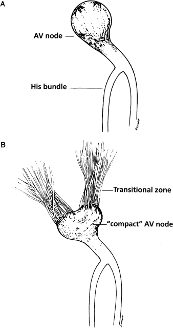
Successfully ablating AV nodal reentrant tachycardia has required a change in the way electrophysiologists visualize the AV node. In the past, most electrophysiologists thought of the AV node simply as a compact, button-like structure, as depicted in Figure 8.1a. It has now become apparent that the AV node behaves more as depicted in Figure 8.1b. The AV node does indeed appear to have a compact distal component (i.e. the part of the node that gives rise to the His bundle), but the more proximal portion of the AV node appears to be “diffuse.”
Figure 8.1 “Old” and “new” concepts of AV node anatomy and physiology. (a) The AV node as it commonly used to be conceived, namely as a compact “button” of specialized tissue. (b) The AV node as it is currently conceptualized by electrophysiologists. In this “new” model, tracts of conducting fibers coalesce to form the compact AV node. The transition from atrial electrophysiology to AV nodal electrophysiology probably occurs proximal to the compact node. Anatomists have been describing this for years, but until ablationists arrived on the scene there seemed to be no good reason to believe them.
To visualize what this means, it is helpful to imagine the course of the electrical impulse as it approaches the AV node from the atria. We have seen that the electrical impulse arises in the sinus node and then travels across the atria in a radial fashion. Recent findings suggest that as this electrical impulse approaches the AV node, it is gathered into bands of conducting fibers, which coalesce into “tracts”, which in turn coalesce to form the compact AV node. At some point, the cellular electrophysiology of these coalescing tracts changes (in what is referred to as a “transition zone”) from behaving like typical atrial tissue to behaving like typical AV nodal tissue. Thus, the point at which the AV node “begins” is inherently indistinct and diffuse, and probably varies from patient to patient.
The tracts of atrial fibers that coalesce to form the AV node are ill-defined, and until recently were completely theoretical. It now appears, however, that (at least in patients with AV nodal reentrant tachycardia, and probably in all individuals) two distinct tracts can be localized anatomically—the anterior tract (which corresponds to the fast AV nodal pathway) and the posterior tract (which corresponds to the slow AV nodal pathway).
The “classic” way of visualizing the two pathways involved in AV nodal reentrant tachycardia is shown in Figure 6.11, in which the two tracts are seen as a functional division within the button-like AV node. To visualize the dual AV nodal pathways as currently conceptualized, one must be familiar with the anatomy of Koch’s triangle (Figure 8.2).
Figure 8.2 The triangle of Koch. Long described by anatomists and long ignored by electrophysiologists, Koch’s triangle has become vitally important in performing transcatheter ablations. Koch’s triangle is defined posteriorly by the os of the coronary sinus. The apex of the triangle is defined anteriorly by the His bundle. The tendon of Todaro and the tricuspid valve annulus compose the other two sides of the triangle. In the electrophysiology laboratory, the landmarks of Koch’s triangle are identified by one catheter recording the His deflection and by another placed in the os of the coronary sinus. Koch’s triangle lies between these two catheters.
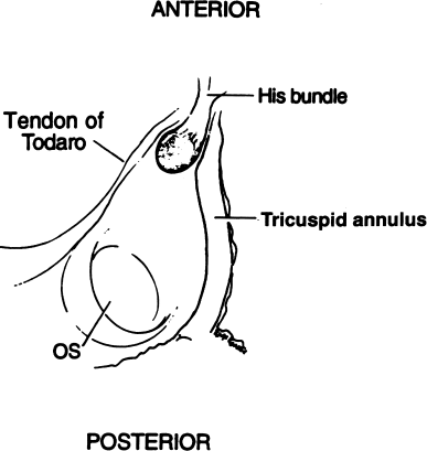
The three sides of Koch’s triangle are defined by the tricuspid annulus (the portion of the annulus adjacent to the septal leaflet of the tricuspid valve), the tendon of Todaro, and the os of the coronary sinus. The His bundle is located at the apex of Koch’s triangle. Therefore, the major landmarks that define Koch’s triangle (the tricuspid valve, the os of the coronary sinus, and the His bundle) are readily identifiable during electrophysiologic testing.
It is important to recognize that the apex of Koch’s triangle (i.e. the angle where the AV node and His bundle reside) is an anterior structure—in fact, the apex of Koch’s triangle defines the anterior aspect of the atrial septum. In contrast, the os of the coronary sinus is a posterior structure and defines the posterior portion of the atrial septum.
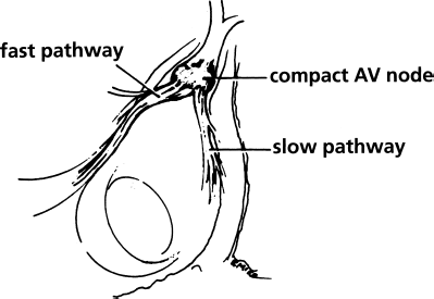
In patients with AV nodal reentrant tachycardia, the fast and slow pathways can be visualized as two tracts of atrial fibers that coalesce to form the compact AV node (Figure 8.3). The fast pathway is an anterior and superior tract of fibers, located along the tendon of Todaro. The slow pathway is a posterior and inferior tract of fibers, located along the tricuspid annulus near the os of the coronary sinus. Thus, the anatomic correlates of the “functional” dual AV nodal pathways have now been identified. Because the two pathways can be discretely localized, they can be discretely ablated.
Figure 8.3 The fast and slow pathways in patients with AV nodal reentrant tachycardia, relating to Koch’s triangle. The dual AV nodal pathways seen in patients with AV nodal reentrant tachycardia have classically been considered to lie within a button-like AV node. Electrophysiologists performing RF transcatheter ablation, however, have now clearly shown that the fast and slow pathways are readily discernible and can be distinctly localized within Koch’s triangle. Both pathways appear to be located proximally to the compact AV node. The fast pathway is an anterior and superior structure and lies near the compact AV node along the tendon of Todaro. The slow pathway is a posterior and inferior structure and can usually be identified along the tricuspid annulus near the os of the coronary sinus. Because the slow pathway is farther away from the AV node than the fast pathway, the slow pathway can usually be selectively ablated without causing complete heart block.
When the anatomy of dual AV nodal pathways was first recognized, most attempts at curing AV nodal reentry focused on ablating the fast pathway. These attempts were generally successful, but unfortunately they yielded a relatively high incidence of complete heart block (up to 20%). The heart block most likely resulted from the fact that the fast pathway and the compact AV node are in close proximity (i.e. both structures are anterior).
The ablation of AV nodal reentry in recent years has been generally accomplished by ablating the slow pathway. Since the slow pathway is posterior, it is relatively distant from the AV node, and thus ablation of this structure yields a low incidence of complete heart block (generally less than 1%).
In general, two approaches are commonly used for ablation of the slow AV nodal pathway—the “mapping” approach and the anatomic approach. Both approaches begin by first identifying the anatomic limits of Koch’s triangle, by placing one catheter in the His position and another in the os of the coronary sinus. The ablation catheter is then advanced from the femoral vein to the tricuspid annulus, near the os of the coronary sinus.
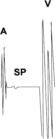
With the “mapping” approach, the ablation catheter is carefully manipulated along the tricuspid annulus, searching for discrete “slow potentials” that presumably represent depolarization of the slow pathway itself (Figure 8.4). These slow potentials are located between the atrial and ventricular deflections in the intracardiac electrogram. Mapping of AV nodal reentrant tachycardia is thus best accomplished during sinus rhythm and not during tachycardia, so that the atrial and ventricular deflections during mapping remain separate and distinct. When the slow potentials are identified, an RF lesion applied at their location almost always ablates the slow pathway.
Figure 8.4 Slow AV nodal pathway potential. Mapping of the slow pathway in patients with AV nodal reentrant tachycardia is accomplished by seeking the slow potential (SP) along the tricuspid annulus within Koch’s triangle. See text for details. A, atrial deflection; V, ventricular deflection.
With the anatomic approach to slow pathway ablation, no attempt is made to map the slow potentials. Instead, ablation sites are identified by fluoroscopic means. Generally, the length of the tricuspid annulus between the os of the coronary sinus and the His bundle is visually divided into three equal sections—posterior (closest to the os of the coronary sinus), middle, and anterior (closest to the His bundle). The ablation catheter is positioned across the tricuspid valve in the posterior section and gradually withdrawn until both atrial and ventricular deflections are recorded, with the ventricular deflection being larger than the atrial deflection. An RF lesion is made, and if the slow pathway has not been successfully ablated, the catheter is moved further anteriorly and the procedure is repeated. Lesions are placed in each of the three sections serially, from posterior to anterior, until the slow pathway has been ablated.
Many electrophysiologists have evolved an integrated approach which begins with ablations posteriorly and moving anteriorly (as with the anatomic approach), but which adds at least a brief search for slow pathway potentials within that anatomic zone prior to applying RF energy.
Accelerated junctional tachycardia occurs during RF application in virtually 100% of successful slow pathway ablations. Therefore, if no tachycardia occurs after 10–15 seconds of RF application, the RF should be terminated and the catheter repositioned. If tachycardia does occur, 30–60 seconds of RF energy should be applied. Successful ablation is documented by confirming that the physiology of dual AV nodal pathways is no longer present (see Chapter 6).
When one or both of these techniques for slow pathway ablation is used, successful treatment of AV nodal reentrant tachycardia can be achieved in over 98% of patients, with a very low risk of producing complete heart block.
Ablation of Bypass Tracts
In the late 1980s, RF ablation of bypass tracts was considered a difficult and somewhat mystical technique performed by only a few adventurous shamans. During the 1990s, however, it evolved into a widely available and highly effective procedure. For most patients with significantly symptomatic or life-threatening bypass tracts, RF ablation is now the therapy of choice.
Characteristics of Bypass Tracts
As noted in Chapter 6, bypass tracts are tiny bands of myocardial tissue that form a bridge across the AV junction, connecting atrial tissue to ventricular tissue. They can occur anywhere along the AV groove, except along the portion directly between the mitral and aortic valves. Because they are composed of bands of myocardial tissue, bypass tracts tend to exhibit the electrophysiologic features of myocardial tissue instead of AV nodal tissue; that is, their refractory periods tend to shorten instead of lengthen with decreases in cycle length, and they tend to develop second-degree block in a Mobitz II pattern instead of a Mobitz I pattern.
Localization of bypass tracts begins by studying the surface ECG and continues with intracardiac mapping.
ECG Localization of Bypass Tracts
Bypass tracts are divided into five general categories according to their location (Figure 8.5). These categories are left free wall, right free wall, posterior septal, anterior septal, and midseptal. The general approach to mapping in the electrophysiology laboratory is different for each of these categories, so it is important to have some idea as to the location of a bypass tract before the ablation procedure begins. In most cases, the surface ECG fortunately gives a very good indication of where the bypass tract is located.
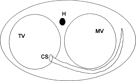
Figure 8.5 Location of bypass tracts. The anatomic structures shown in this figure are the mitral valve (MV), the tricuspid valve (TV), the coronary sinus (CS), and the His bundle (H). LFW, left free-wall tracts; LPS, left paraseptal tracts; PS, posteroseptal tracts; RPS, right paraseptal tracts; RFW, right free-wall tracts; AS, anteroseptal tracts; MS, midseptal tracts; MS(L), left-sided midseptal tracts. See text for details.
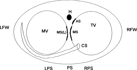
Table 8.1 lists the ECG criteria for grossly localizing bypass tracts. The “key” is to look for the leads with the negative delta wave, because the negative delta wave “points” to the bypass tract (Figure 8.6).
Figure 8.6 Electrocardiographic manifestations of the major categories of bypass tract. Typical electrocardiographic patterns are shown for left free-wall tracts (LFW), right free-wall tracts (RFW), posteroseptal tracts (PS), and anteroseptal tracts (AS). See text and Table 8.1 for details.
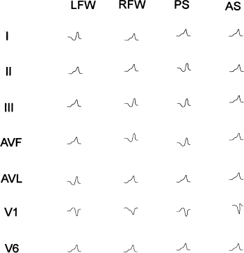
Table 8.1 Electrocardiographic localization of bypass tracts.
| Location of tract | Characteristics of preexcited QRS |
| Left free wall | Negative delta wave in AVL and often in lead I. Positive delta wave in inferior and precordial leads. Normal QRS axis. |
| Right free wall | Negative delta wave in leads III and AVF. Positive delta waves in leads I and II. Normal QRS axis. |
| Posteroseptal | Negative delta waves in inferior leads. Positive delta waves in leads I and AVL. R/S ratio in V1 < 1; left superior axis. |
| Anteroseptal | Negative delta wave in leads V1 and V2. Positive delta wave in leads I and II. Normal QRS axis. |
| Midseptal | ECG similar to anteroseptal, except that in inferior leads, delta waves are not positive. |
Consider the delta waves in ECG lead I, which is a “left-sided” lead. Delta waves in lead I are negative for left free-wall tracts, are biphasic (or isoelectric) for left posterior to right posterior tracts, and are positive for right free-wall tracts.
The delta waves in lead V1 (a right-sided lead) are positive for left free-wall and posterior septal tracts and negative for right free-wall tracts. They are biphasic (or isoelectric) for anteroseptal tracts.
The delta waves in leads II, III, and AVF (inferior leads) are negative for posterior septal tracts and become positive as the tracts move anteriorly toward the anteroseptal regions.
Based on this general concept, and on the more specific criteria listed in Table 8.1, a very good idea of the location of a bypass tract can be ascertained before the electrophysiologic procedure is begun—and thus, before an accurate preliminary action plan is made.
Considerations For Successfully Mapping and Ablating Bypass Tracts
Before outlining specific approaches to various types of bypass tract, let us review some general considerations for successfully mapping and ablating these tracts:
Figure 8.7 Depiction of the narrow AV interval seen when the mapping catheter is in proximity to the bypass tract. Compare this to the more “usual” AV interval shown in Figure 8.4. When mapping bypass tracts, the optimal localized AV interval is generally less than 60 msec.
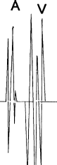
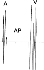
Figure 8.8 Recording of a bypass-tract potential. Often, a localized potential from the bypass tract itself (AP, “accessory pathway” potential) can be recorded from a well-positioned mapping catheter.
The Approach to Bypass Tracts According to Location
Left Free-Wall Bypass Tracts
More than 50% of bypass tracts referred for RF ablation have been located in the left free wall. These tracts cross the AV groove along the anterolateral, lateral, posterolateral, or posterior aspects of the mitral valve annulus. The coronary sinus also courses along the same portion of the mitral annulus, and thus provides a convenient means of mapping the annulus in patients with left free-wall pathways.
Standard electrode catheters are placed in the high right atrium, His position, and right ventricular apex. A multipolar electrode catheter is placed into the coronary sinus (often a 10-lead catheter is used) and multiple bipolar recordings are established along its length. After the earliest sites of antegrade and retrograde preexcitation are approximated using the electrodes within the coronary sinus, the mapping and ablation catheter is inserted.
There are two general approaches for ablating left free-wall pathways: the retrograde approach and the transseptal approach.
The retrograde approach is the most commonly used and usually yields favorable results. The mapping catheter is inserted through a femoral artery and advanced across the aortic valve into the left ventricle. The catheter tip is then maneuvered into the AV groove beneath the mitral valve leaflets and the bypass tract is localized.
The transseptal approach is also very effective in skilled hands. The mapping catheter is inserted through a femoral vein and advanced across the intraatrial septum into the left atrium. In most cases, crossing the intraatrial septum requires that a puncture be made through the septal wall, using a catheter-based tool designed specifically for that purpose. When the transseptal approach is used, the atrial aspect of the mitral annulus is mapped.
With either approach, the multipolar coronary sinus catheter is used as a stable reference for guiding mapping maneuvers. Also with either approach, successful ablation of left free-wall bypass tracts can be achieved in more than 95% of cases.
Right Free-Wall Bypass Tracts
Right free-wall tracts are seen in approximately 10% of patients with bypass tracts referred for ablation. These tracts are more difficult to map and ablate than left free-wall tracts because a stable catheter position is more difficult to attain and there is no anatomic structure analogous to the coronary sinus to aid in mapping.
Standard electrode catheters are placed in the high right atrium, His position, right ventricular apex, and coronary sinus. The mapping and ablation catheter is usually inserted via a femoral vein, advanced across the tricuspid valve, and then withdrawn so that the mapping electrodes are positioned along the tricuspid annulus in such a way that both atrial and ventricular deflections are recorded. Mapping is often conducted using the left anterior oblique (LAO) projection, which allows the tricuspid annulus to be visualized as the face of a clock (Figure 8.9). In this projection, the His bundle is located at approximately 1 o’clock, and the os of the coronary sinus at approximately 5 o’clock. If the bypass tract proves to be difficult to map, or if catheter stability is a problem, alternative approaches can be tried. Introducing the mapping catheter via the superior instead of the inferior vena cava is sometimes helpful. Long intravascular sheaths can also be used to lend stability to the mapping catheter.
Figure 8.9 Orientation of the tricuspid annulus (TV) in the left anterior oblique (LAO) projection. In the LAO projection, the tricuspid annulus can be visualized as the face of a clock, with the His bundle (H) in the 1 o’clock position and the os of the coronary sinus (CS) in the 5 o’clock position. MV, mitral valve annulus.
Stay updated, free articles. Join our Telegram channel

Full access? Get Clinical Tree


