FIGURE 7-1 Areas of resistance. A: Two areas of resistance are met with right TFA. B: One area of resistance is/ met with left TRA. C: One area of resistance is met with TFA. DAo, descending aorta; RSA, right subclavian artery; RCCA, right common carotid artery; LCCA, left common carotid artery; LSA, left subclavian artery; TRA, transradial access; TFA: transfemoral access. (From Patel T, Shah S, Rihal CS, et al. Cannulation of the coronary ostia. In: Patel’s Atlas of Transradial Intervention: The Basics and Beyond. 2nd ed. Malvern, PA: HMP Communications, 2012.)

FIGURE 7-2 Differential catheter course through transfemoral (A) and transradial (B) vascular access. Because of the curvature between the brachiocephalic trunk and the ascending aorta, a shorter secondary curve, usually by 0.5 cm, is needed for successful cannulation of the LCA with a JL catheter. The operators should use a JL 3.5 (B) instead of a JL 4.0 (A). (Courtesy of Medtronic.)
The anatomic differences between the left and right TRAs have practical implications, especially during the learning curve. Randomized data comparing right versus left radial access suggest that the initial adoption of left TRA is associated with a significantly shorter learning curve, with progressive reductions in cannulation and fluoroscopy times as the operator volume increases.5,6 After the initial 50 to 100 cases, operators can transition to right TRA, which is ergonomically more convenient without the need to lean over the patient to reach the left upper extremity.
Given the occasional anatomical challenges, maintaining access to the ascending aorta is important. This can be done by using an exchange-length (260 cm) guidewire or by using a standard-length guidewire and constantly flushing the catheters with saline during catheter removal so that the tip of the guidewire stays in place.
Use of Respiration
Vessel tortuosity, particularly in older patients with long-standing hypertension, can pose a challenge in the delivery of the catheter to the ascending aorta, and this accounts for about half of all percutaneous coronary intervention (PCI) failures via the TRA.7 At times, the wire may preferentially enter the descending aorta, and deep inspiration may facilitate motion of the wire into the ascending aorta by changing the angle of the innominate artery as it branches from the aorta (Fig. 7-3).8 In the event that this is unsuccessful, the catheter can be advanced over the wire until it reaches the aortic arch; then it can be rotated until it points toward the ascending aorta. From there, the wire can be advanced into the aortic root. Alternatively, the use of a hydrophilic wire and repeating the inspiratory maneuver can help. Inspiration may also be useful in cases where deep engagement of the coronary is desired to facilitate PCI. In these situations, the patient is instructed to take a deep breath as the catheter is rotated into the ostium of the artery.9
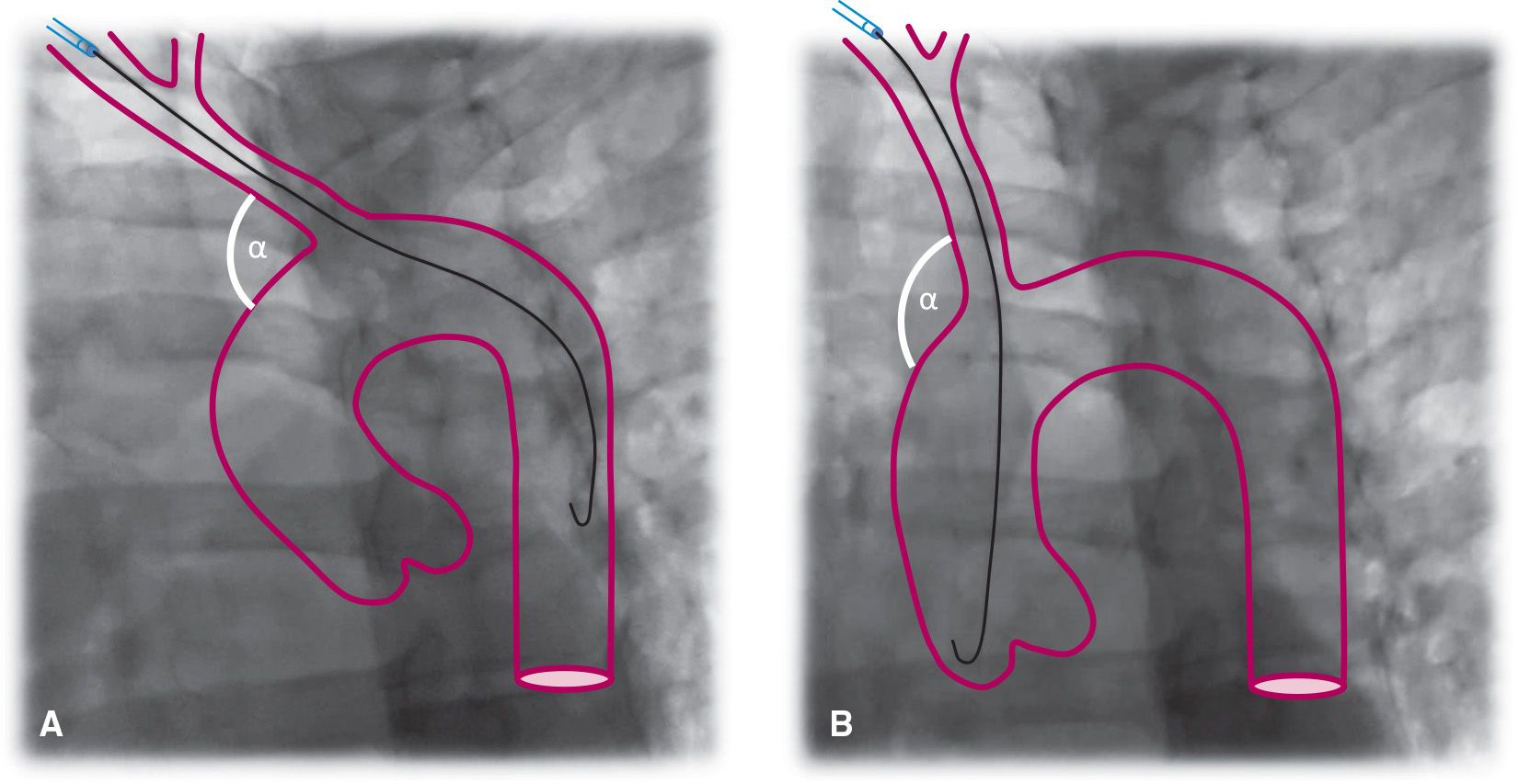
FIGURE 7-3 Effect of Inspiration. A: During expiration there is a more acute angle (a) between the brachiocephalic trunk and the ascending aorta; therefore, the wire takes a more horizontal direction toward the descending aorta. B: During deep inspiration, the diaphragm lowers the heart and straightens the angle (a) between the brachiocephalic trunk and the ascending aorta. The wire takes a more vertical direction toward the ascending aorta.
Catheter Selection for Diagnostic Coronary Angiography
Initially, the catheters used to perform TRA catheterization were those mainly developed for TFA (Judkins, Amplatz, and multipurpose). However, with better understanding of the anatomic challenges and the more central position within the ascending aorta that the catheters adopt when advanced from the upper limb, new catheters were developed that can be used to cannulate both coronary arteries. Newer catheters have a large loop at their distal end to move the catheters away from the central position within the aorta. Incorporation of a flat portion within the loop of the catheter provides sufficient support against the aorta; this is particularly important to maintain catheter stability especially during percutaneous interventions, and allows the operator to more easily keep the catheter in place. Figure 7-4 displays the most commonly used catheter shapes for TRA procedures.10,11
Catheters originally designed for TFA can be used to perform TRA catheterization; in fact, the Judkins catheters may be the easiest catheters to use in the early learning stages. The operator should be aware, however, of the potential of the JL catheter to cause injury to the left main artery when used via the TRA, because of the upward force stored by the tip of this catheter. If this catheter is used, downsizing the curve of the JL catheter from 4.0 to 3.5 may be required; very careful manipulation is also necessary to avoid any trauma to the coronary arteries (Fig. 7-2). One drawback to the use of “femoral catheters” is the almost obligatory exchange of catheters, which may increase procedural and fluoroscopy times. This may be avoided by the use of a single universal catheter approach to selectively engage both coronaries. This approach may be technically more challenging at first. An example of a “radial” catheter is the Tiger catheter, made with stainless steel incorporated with polyurethane. The loop at the end of the catheter moves the body of the catheter from the central position that occurs naturally as a result of the angle between the innominate artery and the aorta. A flat segment in the third portion of the loop rests on the contralateral aortic wall to the coronary that is being engaged. This gives the catheter extra support and stabilizes it against the aorta. Engaging the coronaries can be done at 30° to 45° in either the left anterior oblique (LAO) or the anterior–posterior (AP) views. The catheter may be delivered under fluoroscopy to the ascending aorta and advanced to the level of the aortic valve with the use of a standard 0.035-inch J- or hydrophilic wire, which should be held in place below the LCA. With the catheter tip facing left, the catheter may spontaneously enter the LCA with slow pullback of the wire. It is important to retract the wire slowly, as a rapid retraction may cause the catheter to flip upward into the ascending aorta. If the catheter does not spontaneously enter the LCA upon pullback of the wire, slight clockwise or counterclockwise torquing may be needed. Slight pullback of the catheter usually disengages it from the LCA. With clockwise motion, the catheter tip should enter the right sinus of Valsalva and engage the right coronary artery (RCA). In a minority of cases, the Tiger catheter may fail to engage the LCA and this catheter may be exchanged for a JL catheter. The RCA can also be successfully engaged with the Tiger catheter.3,8 The operator should be aware that this catheter does have a tendency to easily disengage from the coronary ostium, particularly the left coronary, when a forceful injection of contrast is given; however, this nuisance is easily overcome with operator awareness, maintained finger torque at the hub of the catheter, and a smoother injection.
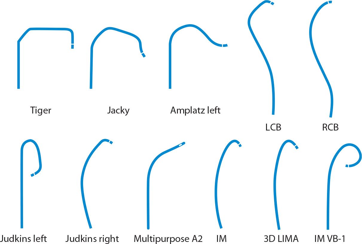
FIGURE 7-4 Most frequently used diagnostic coronary catheter shapes in transradial coronary angiography.
A few studies have compared the efficiency of the single- versus dual-catheter technique. A Canadian observational study assessed fluoroscopy time, radiation dose, and the number of crossovers with these techniques in 1,384 patients undergoing TRA native coronary angiography by 14 different operators. Most cases (85%) were performed with Judkins catheters (dual-catheter technique), while a number of different catheters, including Amplatz, Barbeau, and multipurpose, were used for the single-catheter technique. The average fluoroscopy time was 2.6 minutes. The dual-catheter technique was associated with fewer crossovers, lower radiation exposure (2,933 vs 3,352 cGy . cm2, P = 0.0001), and shorter fluoroscopy time (2.6 vs 2.8 minutes, P = 0.03). It should be noted that the majority of cases were performed with two Judkins catheters and that the only “radial-specific catheter” in this study was the Barbeau catheter, which is currently not widely utilized in practice. A randomized study comparing Judkins (JL and JR) and the Tiger catheters demonstrated a significant reduction in procedural and fluoroscopy times by 40% and 33%, respectively, with the Tiger catheter. Technique crossover was rare, and RCA and LCA angiographies were completed in 100% and 98% of cases with the Tiger catheter, and in 91% and 95% with Judkins catheters.3
For patients with prior CABG, the left radial approach may be preferred because it allows easier cannulation of the LIMA. For SVGs, left TRA offers a similar experience as TFA; however, right TRA is usually associated with lengthier catheter manipulation and procedural time. In patients whose SVGs are not marked, it is advisable to perform ascending aortography in order to visualize the origin of the grafts in the aorta and select the catheters accordingly. Figure 7-5 provides guidance on the choice of catheters for selective cannulation of SVGs according to the location of the proximal anastomosis in the ascending aorta and whether the procedure should be more conveniently performed from left or right TRA. Multipurpose or JR 4 catheters can be used to cannulate right-sided SVGs usually to the RCA. Amplatz left (AL) catheters are well suited for grafts arising from the anterior or left walls of the aorta usually to the LCA. There is an area in the right wall of the aorta, adjacent to the origin of the innominate artery, that is difficult to reach, especially through right TRA, and catheters with more acute curves may be needed, such as extra backup or hockey stick.12
Adequate angiographic imaging of a patent internal mammary artery (IMA) graft is essential in the evaluation of patients with prior coronary bypass surgery. An important theoretical advantage of the TRA for IMA cannulation is the absence of catheter manipulation in the aortic arch, which potentially reduces the incidence of consequent cerebrovascular embolization and stroke. Homolateral TRA is associated with significant reductions in times to cannulation and visualization compared with TFA.13 An important detail to keep in mind is that with the homolateral TRA approach, the take-off angle of the IMA is more frequently acute, as opposed to the obtuse angle that is encountered from the femoral approach. In most cases, the IMA can be successfully engaged with a regular IM catheter. However, when this angle is sharper, a more acute catheter curve such as the IM-VB1 may be needed (Fig. 7-6). Sharp angles are particularly frequent with the right IMA.12
The left IMA can be selectively cannulated and imaged from the contralateral right TRA. Although this technique is routinely used by some expert operators, the procedure involves more complex manipulation with multiple catheter exchanges because of the complex angles of both subclavian arteries in relation to the aortic arch.14 To cannulate the contralateral IMA, a 0.035-inch wire is placed in the descending aorta and a catheter with a distal bend, such as JL 3.5, left coronary bypass (LCB), or Jacky/Tiger, is advanced over the wire. The wire is removed and the tip of the catheter rotated such that the tip points upward toward the left subclavian artery. Then a 0.035-inch or 0.032-inch exchange-length soft-angled-tip hydrophilic wire is advanced into the left subclavian artery and the tip positioned as far as possible beyond the brachial artery. The distal end of the wire can then be trapped by inflating a blood pressure cuff in the left arm or by asking the patient to flex the forearm.14 The initial catheter used to direct the wire is then exchanged for a 4F IMA or 3D LIMA catheter. The use of smaller 4F catheters is usually recommended because these catheters are malleable and can track over the wire without prolapsing into the descending aorta. The catheter is then advanced into the subclavian artery beyond the origin of the left IMA. The hydrophilic wire is removed. Then, maneuvering very gently, the catheter is rotated counterclockwise and carefully pulled back seeking the origin of the left IMA. Figure 7-7 illustrates each one of these procedural steps. The operator needs to keep in mind that catheter manipulations to engage the contralateral IMA are time-consuming, especially in the elderly with tortuous vessels, and if the catheter is pulled proximal to the IMA origin and/or falls into the aortic arch, the whole process has to be reinitiated. Cha and colleagues published a study involving a series of 184 patients who underwent cardiac catheterization with left IMA angiography through right TRA.15 They specifically designed a modified Simmons catheter with a 0.5-cm modified tip bent 80° laterally and 80° anteriorly. Left IMA was selectively cannulated in 164 (89%) patients, and subselectively in the remaining patients. There were no reported complications. The average time from catheter introduction to successful left IMA engagement was 3.7 minutes.
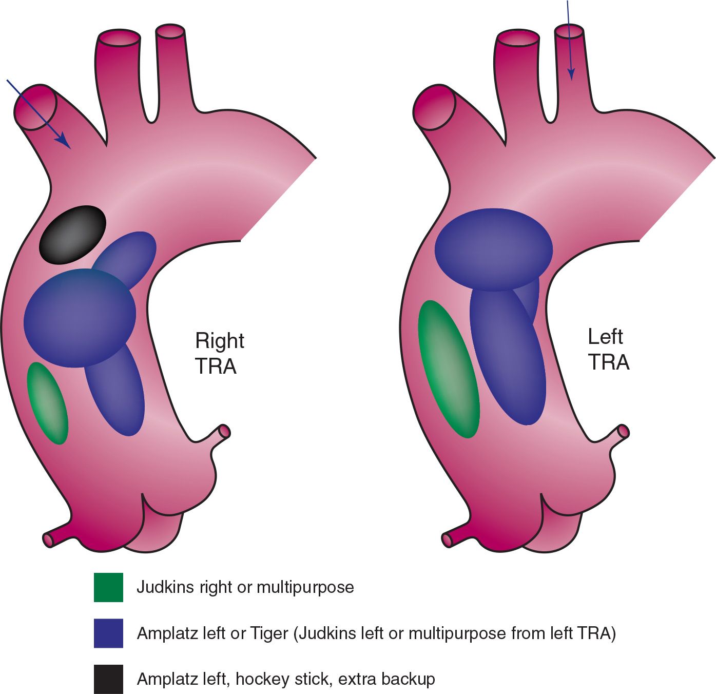
FIGURE 7-5 Catheter selection for cannulation of SVGs to the left coronary and the RCA according to right or left transradial approach. (Adapted from Burzotta F, Trani C, Hamon M, et al. Transradial approach for coronary angiography and interventions in patients with coronary bypass grafts: tips and tricks. Catheter Cardiovasc Interv. 2008;72(2):263–272.)
In practice, there is a wide variation in preference for diagnostic catheters as depicted in Figures. 7-8 and 7-9. A large survey including 874 interventional cardiologists from all over the world demonstrated that almost half of operators prefer using two Judkins catheters for engagement of native coronary arteries, JL 3.5 and JR 4.0 for the LCA and RCA, respectively. The most popular single-catheter technique choice seems to be the Tiger catheter, used in approximately 15% of cases. Other less frequent choices (<10%) include multipurpose and Amplatz catheters. A similar variation in choice is observed for saphenous bypass grafts. About half of operators prefer the JR 4.0 for left and right SVGs. Operators also appreciate the features of the AL catheters for SVGs to the LCA (23%) and the multipurpose for SVGs to the RCA (24%).16
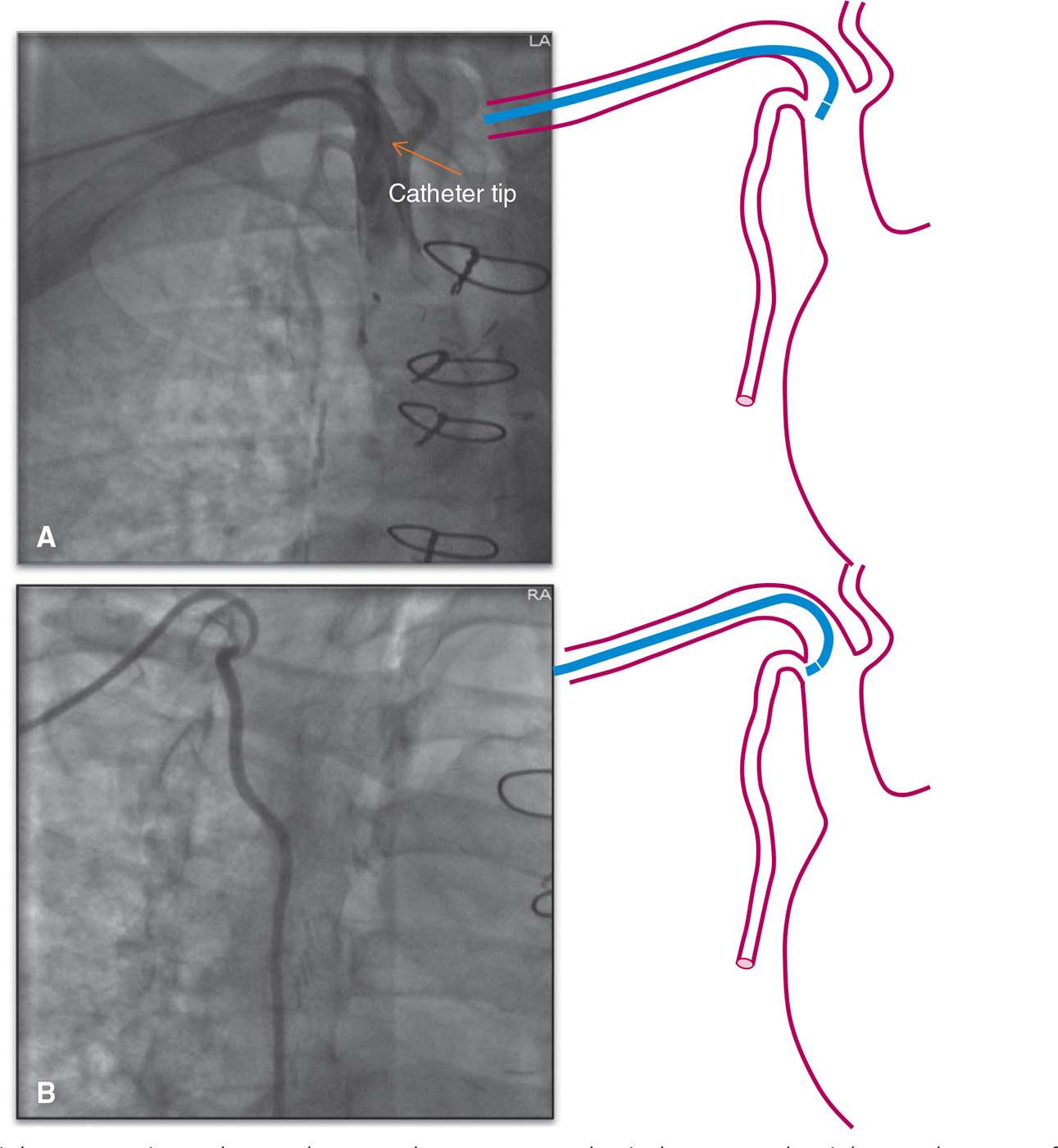
FIGURE 7-6 Right IMA angiography. A: The IM catheter cannot selectively engage the right IMA because of its sharp origin angle providing suboptimal images. B: A more angulated catheter, such as the IM-VB1, can selectively cannulate the right IMA without difficulty providing optimal angiographic opacification of the vessel.
Stay updated, free articles. Join our Telegram channel

Full access? Get Clinical Tree


