An understanding of the basic concepts of cardiac pacing (see Chapter 1: Pacing and Defibrillation) and comprehension of the pacemaker timing cycles of cardiac pacing are important as one approaches the paced electrocardiogram (ECG). The first portion of this chapter provides a detailed description of “timing cycles” and approaches the subject by pacing mode and descriptions of other features that are used with some frequency that can alter the timing cycle. The second portion of the chapter outlines assessment of the paced ECG.
Basic Approach
Paced electrocardiography must be approached systematically, much as nonpaced electrocardiography, chest radiography, or any other diagnostic procedure. Knowing the type of pacemaker, the programmed parameters, and the underlying rhythm necessitating pacing is important in interpreting the paced ECG. Obviously, this information makes the interpretation much easier, but it is frequently not available.
A sensed event occurs when a pacemaker registers activity deemed to be electrical cardiac events; a paced event occurs when the pulse generator delivers current to stimulate the heart. Paced events are followed by blanking periods, during which amplifiers are switched off and no electrical activity is registered. Blanking periods are followed by refractory periods, during which cardiac electrical activity is normally sensed, but the response of the device to the event is limited. For example, atrial events occurring during an atrial refractory period will not be tracked (i.e., followed by a ventricular paced event), but are used to determine whether mode switching should occur. Blanking and refractory periods serve to prevent oversensing of physiologic signals (such as T waves) and cross-chamber sensing. There is some variation among manufacturers as to how blanking and refractory periods are defined and implemented; their role in timing cycles is discussed further below. In defibrillators and in mode switch operation in pacemakers, a series of sensed events augment counters, leading to arrhythmia detection, which may then result in therapy delivery or mode switch. Defibrillator sensing and detection are discussed in greater detail in Chapter 8: Programming.
Pacemaker timing cycles include all potential variations of a single complete pacing cycle (Table 7.1). This could mean the time from paced ventricular beat to paced ventricular beat (VV); from paced ventricular beat to an intrinsic ventricular beat (VR), whether it be a conducted R wave or a premature ventricular contraction; from paced atrial beat to paced atrial beat (AA); from intrinsic atrial beat to paced atrial beat (PA); and so forth. Various aspects of each of these cycles include events sensed, events paced, and periods when the sensing circuit or circuits are refractory or blanked. Each portion of the pacemaker timing cycle should be considered in milliseconds (ms) and not in paced beats per minute (ppm). Although it may be easier to think of the patient’s pacing rate in paced beats per minute, portions of the timing cycle are too brief to be considered in any unit but milliseconds.
Table 7.1 Abbreviations for native and paced events and portions of the timing cycle.
| P | Native atrial depolarization |
| A | Atrial paced event |
| R | Native ventricular depolarization |
| V | Ventricular paced event |
| I | Interval |
| AV | Sequential pacing in the atrium and ventricle |
| AVI | Programmed atrioventricular pacing interval |
| AR | Atrial paced event followed by intrinsic ventricular depolarization |
| ARP | Atrial refractory period |
| PV | Native atrial depolarization followed by a paced ventricular event, P synchronous pacing |
| LRL | Lower rate limit |
| URL | Upper rate limit |
| MTR | Maximum tracking rate |
| MSR | Maximum sensor rate |
| PVARP | Post-ventricular atrial refractory period |
| RRAVD | Rate-responsive atrioventricular delay |
| VA interval | Interval from a ventricular sensed or paced event to an atrial paced event |
| VRP | Ventricular refractory period |
If one knows the relationship between the various elements of the paced ECG, understanding pacemaker rhythms becomes less complicated. Although a native rhythm may be affected by multiple unknown factors, each timing circuit of a pacemaker can function in only one of two states. A given timer can proceed until it completes its cycle; completion results in either the release of a pacing stimulus or the initiation of another timing cycle. Alternatively, a given timer can be reset by a sensed event, at which point it reinitiates the timing cycle.
Pacing Modes
Ventricular Asynchronous Pacing, Atrial Asynchronous Pacing, and Atrioventricular Sequential Asynchronous Pacing
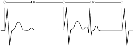
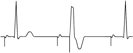
Ventricular asynchronous (VOO) pacing is the simplest of all pacing modes, because there is no sensing and no mode of response. The timing cycle is shown in Fig. 7.1. Irrespective of any other events, the ventricular pacing artifacts occur at the programmed rate. The timing cycle cannot be reset by any intrinsic event. Without sensing, there is no defined refractory period. Atrial asynchronous (AOO) pacing behaves exactly like VOO except that the pacing artifacts occur in the atrial chamber.
Fig. 7.1 The VOO timing cycle consists of only a defined rate. The pacemaker delivers a ventricular pacing artifact at the defined rate regardless of intrinsic events. In this example, an intrinsic QRS complex occurs after the second paced complex, but because there is no sensing in the VOO mode, the interval between the second and the third paced complex remains stable. LR, lower rate (limit).
Dual-chamber, or atrioventricular (AV) sequential asynchronous (DOO), pacing has an equally simple timing cycle. The interval from atrial artifact to ventricular artifact (atrioventricular interval [AVI]) and the interval from the ventricular artifact to the subsequent atrial pacing artifact (ventriculoatrial, or atrial escape, interval [VA interval]) are fixed. The intervals never change, because the pacing mode is insensitive to any atrial or ventricular activity, and the timers are never reset (Fig. 7.2).
Fig. 7.2 The DOO timing cycle consists of only defined atrioventricular (AV) and VV intervals. The ventriculoatrial (VA) interval is a function of the AV and VV intervals. An atrial pacing artifact is delivered, and the ventricular artifact follows at the programmed AV interval. The next atrial pacing artifact is delivered at the completion of the VA interval. There is no variation in the intervals because no activity is sensed, i.e., nothing interrupts or resets the programmed cycles.
(From Hayes DL, Levine PA: Pacemaker timing cycles. In Cardiac Pacing, Ellenbogen KA, ed. Boston, Blackwell Scientific Publications, 1992: 263–308.)
Ventricular Inhibited Pacing
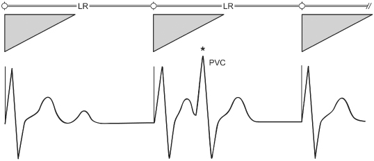
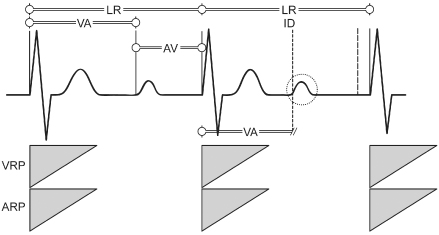
By definition, ventricular inhibited (VVI) pacing (also referred to as inhibited demand pacing) incorporates sensing on the ventricular channel, and pacemaker output is inhibited by a sensed ventricular event (Fig. 7.3). VVI pacemakers are refractory for a period after a paced or sensed ventricular event, the ventricular refractory period (VRP). Ventricular events occurring within the VRP do not reset the ventricular timer (Fig. 7.4). (Every pacemaker capable of sensing and all defibrillators must include a refractory period in their basic timing cycles. Refractory periods prevent the sensing of early inappropriate signals, such as the evoked potential and repolarization [T wave].)
Fig. 7.3 The VVI timing cycle consists of a defined lower rate (LR) limit and a ventricular refractory period (VRP, represented by triangle). When the LR limit timer is complete, a pacing artifact is delivered in the absence of a sensed intrinsic ventricular event. If an intrinsic QRS occurs, the LR limit timer is started from that point. A VRP begins with any sensed or paced ventricular activity.
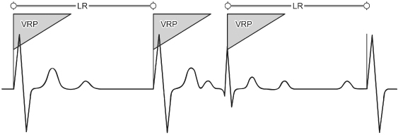
Fig. 7.4 If, in the VVI mode, an intrinsic ventricular event (*) occurs during the ventricular refractory period (VRP, represented by triangle), it is not sensed and therefore does not reset the lower rate (LR) limit timer. PVC, premature ventricular contraction.
Atrial Inhibited Pacing
Atrial inhibited (AAI) pacing, the atrial counterpart of VVI pacing, incorporates the same timing cycles, with the obvious difference that pacing and sensing occur from the atrium and pacemaker output is inhibited by a sensed atrial event (Fig. 7.5). An atrial paced or sensed event initiates a refractory period during which electrical signals are ignored by the pacemaker. Because we are most accustomed to devices with ventricular sensing, confusion can arise when ventricular events are appropriately ignored [not seen] in the AAI/AAIR pacing mode. For example, in addition to the intrinsic QRS that follows a paced atrial beat, if a premature ventricular beat occurs, it does not inhibit an atrial pacing artifact from being delivered. When the AA timing cycle ends, the atrial pacing artifact is delivered regardless of ventricular events, because an AAI pacemaker should not sense anything in the ventricle. If a ventricular event is large enough that it is inappropriately sensed on the atrial lead, the event is termed far-field sensing (Fig. 7.6). In this situation, the atrial timing cycle is reset, leading to a pacing rate slower than the programmed lower rate limit (Fig. 7.6). Sometimes this anomaly can be corrected by making the atrial channel less sensitive or by lengthening the refractory period. Interpretation can be made easier in some devices when a programmable ADI mode is available. This mode is operationally the same as AAI pacing mode, but ventricular events are recorded on the diagnostic channels (Fig. 7.7).
Fig. 7.5 The AAI timing cycle consists of a defined lower rate (LR) limit and an atrial refractory period (ARP). When the LR limit timer is complete, a pacing artifact is delivered in the atrium in the absence of a sensed atrial event. If an intrinsic P wave occurs, the LR limit timer is started from that point. An ARP begins with any sensed or paced atrial activity. In the AAI mode, only atrial activity is sensed. In this example, it may appear unusual for paced atrial activity to occur so soon after intrinsic ventricular activity. Because sensing occurs only in the atrium, ventricular activity would not be expected to reset the pacemaker’s timing cycle.
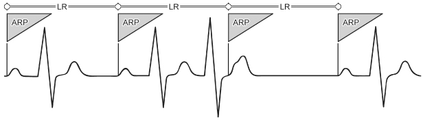
Fig. 7.6 In this example of AAI pacing, the AA interval is 1000 ms (60 ppm). The interval between the second and the third paced atrial events exceeds 1000 ms. The interval from the second QRS complex to the subsequent atrial pacing artifact is 1000 ms. This occurs because the second QRS complex (*) has been sensed on the atrial lead (far-field sensing) and has inappropriately reset the timing cycle. LR, lower rate (limit).
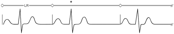
Fig. 7.7 Although an AAI pacemaker is incapable of responding to ventricular events, interpretation is easier if the ventricular events are identified. One manufacturer has a programmable ADI mode in dual-chamber pacemakers. This mode is operationally the same as AAI, but events sensed in the ventricle are recorded on the diagnostics.
(Reproduced with permission from Medtronic Adapta Technical Manual.)
Single-Chamber Triggered-Mode Pacing
Initially developed as a way to defeat the problem associated with oversensing in the inhibited demand mode, the single-chamber triggered mode (AAT, VVT) has its own unique advantages as well as disadvantages. In single-chamber triggered-mode pacing, the pacemaker releases an output pulse every time a native event is sensed (Fig. 7.8). This feature increases the current drain on the battery, accelerating its rate of depletion. This mode of pacing also deforms the intrinsic depolarization, compromising interpretation of the ECG. However, it can serve as an excellent marker for the site of sensing within a complex. It can also prevent inappropriate inhibition from oversensing when the patient does not have a stable native escape rhythm.
Fig. 7.8 In the VVT mode, when an intrinsic atrial event occurs a pacing artifact is delivered at the point of sensing (TP). If the lower rate limit timer is completed, a pacing artifact is delivered with paced depolarization.

Rate-Modulated Pacing
Single-Chamber Rate-Modulated Pacing
Single-chamber pacemakers capable of rate-modulated (SSIR) pacing can be implanted in the ventricle (VVIR) or atrium (AAIR). The timing cycles for SSIR pacemakers are not significantly different from those of their non-rate-modulated counterparts. The timing cycle includes the basic VV or AA interval and a refractory period from the paced or sensed event. The difference lies in the variability of the VV or AA interval (Fig. 7.9). Depending on the sensor incorporated and the level of exertion of the patient, the basic interval shortens from the programmed lower rate limit (LRL). An upper rate limit (URL) must be programmed to define the absolute shortest cycle length allowable. Some SSIR pacemakers incorporate a fixed refractory period; that is, regardless of whether the pacemaker is operating at the LRL or URL, the refractory period remains the same. Thus, at the higher rates under sensor drive, the pacemaker may effectively become asynchronous, i.e., SOOR, because the period during which sensing can occur is so abbreviated. Native beats falling during the refractory period do not reset timing cycles.
Fig. 7.9 The VVIR timing cycle consists of a lower rate (LR) limit, an upper rate (UR) limit, and a ventricular refractory period (VRP, represented by triangle). As indicated by sensor activity, the VV cycle length shortens accordingly. (The shaded area represents the range of sensor driven VV cycle lengths.) In some VVIR pacemakers, the VRP remains fixed despite the changing VV cycle length and in others the VRP shortens as the cycle length shortens.
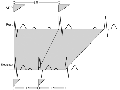
In the VVIR pacing mode the refractory period should be programmed to a short interval to maximize the sensing interval at both the low and high sensor-driven rates. In an AAIR pacing mode, the refractory period should be programmed long enough to avoid far-field sensing and short enough to allow sensing of native atrial events at rates up to the programmed upper sensor rate. Rate-variable or rate-adaptive refractory period as a programmable option, i.e., as the cycle length shortens, the refractory period shortens appropriately, analogous to the QT interval of the native ventricular depolarization, is often available.
Rate-Modulated Asynchronous Pacing
If rate modulation is incorporated in an asynchronous pacing mode, the basic cycle length is altered by sensor activity. In the single-chamber rate-modulated asynchronous (AOOR and VOOR) pacing modes, any alteration in cycle length is due to sensor activity and not to the sensing of intrinsic cardiac depolarizations. In the dual-chamber rate-modulated asynchronous (DOOR) pacing mode, the pacing rate changes in response to the sensor input signal, but not to the native P or R wave.
Atrioventricular Sequential, Ventricular Inhibited Pacing (DVI)
AV sequential, ventricular inhibited (DVI) pacing is rarely used as the programmed pacing mode of choice, but remains a programmable option in some pacemakers. It is helpful to understand the timing cycles for DVI pacing.
By definition, DVI provides pacing in both the atrium and the ventricle (D), but sensing only in the ventricle (V). The pacemaker is inhibited and reset by sensed ventricular activity but ignores all intrinsic atrial complexes.
The timing cycle (VV) consists of the AVI and the VA interval. The basic cycle length (VV), or LRL, is programmable, as is the AVI. The difference, VV − AV, is the VA interval. During the initial portion of the VA interval, the sensing channel is refractory. After the refractory period, the ventricular sensing channel is again operational, or “alert.” If ventricular activity is not sensed by the expiration of the VA interval, atrial pacing occurs, followed by the AVI. If intrinsic ventricular activity occurs before the VA interval is completed, the timing cycle is reset.
Atrioventricular Sequential, Non-P-Synchronous Pacing with Dual-Chamber Sensing (DDI)
AV sequential pacing with dual-chamber sensing, non-P-synchronous (DDI) pacing can be thought of as DDD pacing without atrial tracking. As opposed to the DVI mode just described, DDI incorporates atrial sensing as well as ventricular sensing, which prevents competitive atrial pacing. The DDI mode of response in the atrium is inhibition only; that is, no tracking of P waves can occur. Therefore, the paced ventricular rate cannot be greater than the programmed LRL in the non-rate-adaptive mode. (In the DDI mode there is only one programmable rate; in the DDIR mode there would be, by definition for any sensor-driven mode, a lower rate limit and an upper sensor rate.) The timing cycle consists of the LRL, AVI, post-ventricular atrial refractory period (PVARP), and VRP. The PVARP is the period after a sensed or paced ventricular event during which the atrial sensing circuit is refractory. Any atrial event occurring during the PVARP will not reset timing cycles. If a P wave occurs after the PVARP and is sensed, the subsequent ventricular pacing artifact cannot occur until the VV interval has been completed; i.e., the LRL cannot be violated (Fig. 7.10).
Fig. 7.10 The timing cycle in DDI consists of a lower rate (LR) limit, an atrioventricular (AV) interval, a ventricular refractory period (VRP), and an atrial refractory period (ARP). The VRP is initiated by any sensed or paced ventricular activity, and the ARP is initiated by any sensed or paced atrial activity. DDI can be thought of as DDD pacing without the capability of P wave tracking or DVI without the potential for atrial competition by virtue of atrial sensing. The LR limit cannot be violated even if the sinus rate is occurring at a faster rate. For example, the LR limit is 1000 ms, or 60 ppm, and the AV interval is 200 ms. If a P wave occurs 500 ms after a paced ventricular complex, the AV interval is initiated; but at the end of the AV interval, 700 ms from the previous paced ventricular activity, a ventricular pacing artifact cannot be delivered, because it would violate the LR limit. ID, intrinsic deflection; UR, upper rate (limit); VA, ventriculoatrial (interval).
It bears repeating that because P wave tracking does not occur with the DDI mode, the paced rate is never greater than the programmed base rate (i.e., the LRL). A slight exception to this statement may occur, depending on the timing system incorporated in the pulse generator, when an intrinsic ventricular complex takes place after the paced atrial beat (AR) and inhibits paced ventricular output before completion of the programmed AVI; i.e., AR < AV. In this situation, the cycle length from A to A is shorter than the programmed LRL by the difference between the AR and the programmed AVI.
Atrioventricular Sequential, Non-P-Synchronous, Rate-Modulated Pacing with Dual-Chamber Sensing (DDIR)
The timing cycles for non-P-synchronous, rate-modulated AV sequential (DDIR) pacing are the same as those described above for DDI pacing, except that paced rates can exceed the programmed LRL through sensor-driven activity.
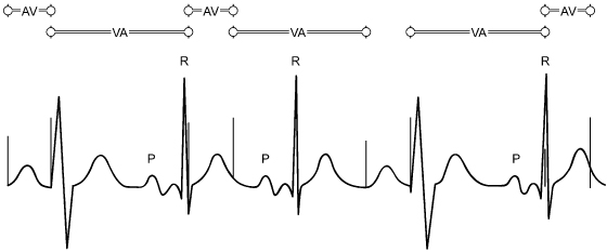
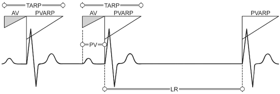
Atrial Synchronous (P-Tracking/P-Synchronous) Pacing (VDD)
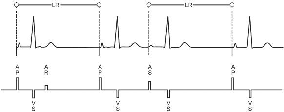
Atrial synchronous (P-tracking/P-synchronous) (VDD) pacemakers pace only in the ventricle (V), sense in both atrium and ventricle (D), and respond both (D) by inhibition of ventricular output by intrinsic ventricular activity (I) and by ventricular tracking of P waves (T). The VDD mode is available as a single-lead pacing system. In this system, a single lead is capable of pacing in the ventricle in response to sensing atrial activity by way of a remote electrode(s) situated on the intra-atrial portion of the ventricular pacing lead. (Single-lead VDD systems are not commonly used.)
The timing cycle is composed of LRL, AVI, PVARP, VRP, and URL. A sensed atrial event initiates the AVI. If an intrinsic ventricular event occurs before the termination of the AVI, ventricular output is inhibited and the LRL timing cycle is reset. If a paced ventricular beat occurs at the end of the AVI, this beat resets the LRL. If no atrial event occurs, the pacemaker escapes with a paced ventricular event at the LRL; i.e., the pacemaker displays VVI activity in the absence of a sensed atrial event (Fig. 7.11).
Fig. 7.11 The timing cycle of VDD consists of a lower rate (LR) limit, an atrioventricular interval (AV), a ventricular refractory period, a post-ventricular atrial refractory period (PVARP), and an upper rate limit. A sensed P wave initiates the AVI (during the AVI, the atrial sensing channel is refractory). At the end of the AVI, a ventricular pacing artifact is delivered if no intrinsic ventricular activity has been sensed, i.e., P wave tracking. Ventricular activity, paced or sensed, initiates the PVARP and the ventriculoatrial interval (the LR limit interval minus the AVI). If no P wave activity occurs, the pacemaker escapes with a ventricular pacing artifact at the LR limit. PV, native atrial depolarization followed by paced ventricular event; TARP, total atrial refractory period.
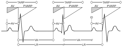
Dual-Chamber Pacing and Sensing with Inhibition and Tracking (DDD)
Although it involves more timers, standard dual-chamber pacing and sensing with inhibition and tracking (DDD) is reasonably easy to comprehend if one understands the timing cycles already discussed. The basic timing circuit associated with LRL pacing is divided into two sections. The first is the interval from a ventricular sensed or paced event to an atrial event. This is the VA interval. The second interval begins with an atrial sensed or paced event and extends to a ventricular event. This interval may be defined as paced in both chambers (AV), intrinsic in both chambers (PR), atrial paced/ventricular intrinsic (AR), or intrinsic atrial/paced ventricular (PV). A sensed atrial event that occurs before completion of the VA interval terminates this interval and initiates the PV interval, and the result is P wave synchronous ventricular pacing. If the intrinsic sinus rate is less than the programmed LRL, AV sequential pacing at the programmed rate or functional single-chamber atrial (AR) pacing occurs (Fig. 7.12).
Fig. 7.12 The timing cycle in DDD consists of a lower rate (LR) limit, an atrioventricular (AV) interval, a ventricular refractory period, a post-ventricular atrial refractory period (PVARP), and an upper rate limit. If intrinsic atrial and ventricular activity occur before the LR limit times out, both channels are inhibited and no pacing occurs. In the absence of intrinsic atrial and ventricular activity, AV sequential pacing occurs (first cycle). If no atrial activity is sensed before the ventriculoatrial (VA) interval is completed, an atrial pacing artifact is delivered, which initiates the AV interval. If intrinsic ventricular activity occurs before the termination of the AV interval, the ventricular output from the pacemaker is inhibited, i.e., atrial pacing (second cycle). If a P wave is sensed before the VA interval is completed, output from the atrial channel is inhibited. The AV interval is initiated, and if no ventricular activity is sensed before the AV interval terminates, a ventricular pacing artifact is delivered, i.e., P-synchronous pacing (third cycle). ID, intrinsic deflection; TARP, total atrial refractory period.
In a DDD system, a sensed or paced atrial event initiates an atrial blanking period, a ventricular blanking period, an atrial refractory period (ARP) and also initiates the AVI (Fig. 7.13). During this portion of the timing cycle, the atrial channel is refractory to any sensed events; nor will atrial pacing occur during this period. The ventricular blanking period initiated by an atrial event prevents ventricular inhibition or initiation of ventricular safety pacing as a result of sensing the atrial event on the ventricular lead.
Fig. 7.13 Schematic representation of the timing cycle interactions of most refractory and blanking periods available on contemporary dual-chamber pacemakers.
(Figure is courtesy of and copyrighted by St. Jude Medical.)
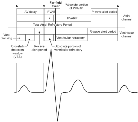
A sensed or paced ventricular event initiates a ventricular blanking period, and a VRP. (A VRP is always part of the timing cycle of any pacing system with ventricular pacing and sensing.) The ventricular blanking period prevents any sensing on the ventricular sensing channel in the period immediately following the ventricular pacing output or sensing of an intrinsic event. The VRP prevents sensing of the evoked potential and the resultant T wave on the ventricular channel of the pacemaker. A sensed or paced ventricular event also initiates a post-ventricular atrial blanking period (PVAB) and a PVARP. (By definition, the sensing circuit is “off” during a blanking period, but conceptually the PVAB as the interval immediately after the ventricular event can be thought of as the “absolute refractory” portion of the PVARP.) The PVAB prevents sensing of far-field R waves and ventricular pacing events on the atrial channel. The PVARP prevents atrial sensing of a retrograde P wave (see Endless-loop tachycardia, below) and also prevents sensing of far-field ventricular events.
A dual-chamber pacemaker can track the atrial rhythm to a defined maximum tracking rate (MTR). The combination of the PVARP and the AVI forms the total atrial refractory period (TARP) (Fig. 7.14). The TARP, in turn, is the limiting factor for the maximum sensed atrial rate that the pacemaker can reach. For example, if the AVI is fixed at 150 ms and the PVARP is fixed at 250 ms, the TARP is 400 ms, or 150 ppm. In this case, a paced ventricular event initiates the 250-ms PVARP, and only after this interval has ended can an atrial event be sensed. If an atrial event is sensed immediately after the termination of the PVARP, the sensed atrial event initiates the AVI of 150 ms. On termination of the AVI, in the absence of an intrinsic R wave, a paced ventricular event occurs, resulting in a VV cycle length of 400 ms, or 150 ppm. Programming a long PVARP limits the upper rate by limiting the maximum sensed atrial rate (Fig. 7.15, top). If the native atrial rate were 151 bpm, every other P wave would coincide with the PVARP, not be sensed, and hence not be tracked, so that the effective paced rate would be approximately 75 ppm, or half the atrial rate (Fig. 7.15, bottom). Pseudo-Wenckebach behavior (Fig. 7.15, top) will result in variable PV intervals that can be quantitated by mathematical equations (Fig. 7.16).1 Figure 7.17 schematically displays the relationship of the effective paced ventricular rate and the atrial rate.
Fig. 7.14 The total atrial refractory period (TARP) is the sum of the atrioventricular (AV) delay and the post-ventricular atrial refractory period (PVARP). SAV, sensed AV interval.
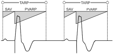
Fig. 7.15 When the sinus rate exceeds the programmed maximum tracking rate, several upper rate (UR) behaviors can occur. In the top panel, pseudo-Wenckebach behavior is seen. If a P wave occurs outside the post-ventricular atrial refractory period (PVARP) and is sensed, the atrioventricular interval (AVI) is initiated. However, a ventricular pacing artifact cannot be delivered at the end of the programmed AVI if this would violate the programmed maximum tracking rate. Instead, the AVI would be lengthened and the ventricular pacing artifact would occur when the maximum tracking rate had “timed out.” For example, if the maximum tracking rate is 120 ppm, or an interval of 500 ms, the AVI is 150 ms, the PVARP is 250 ms and the P wave is sensed 10 ms after completion of the PVARP, or 260 ms after the preceding ventricular event, the next ventricular pacing artifact could not be delivered for 240 ms (500–260 ms). In the bottom panel, 2 : 1 UR behavior occurs when every other sinus beat falls in the PVARP. ID, intrinsic deflection.
(From Hayes DL. DDDR timing cycles: upper rate behavior. In: Barold SS, Mugica J, eds. New Perspectives in Cardiac Pacing, 3rd edn. Mount Kisco, NY: Futura Publishing Co., 1993: 33–57, by permission of Futura Publishing Co.)
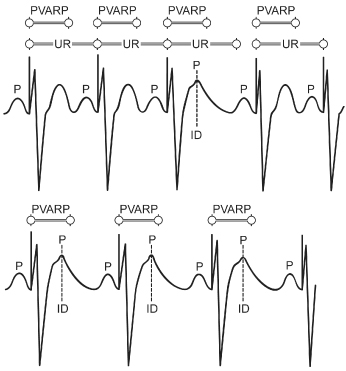
Fig. 7.16 Electrocardiographic tracing from a patient with pseudo-Wenckebach upper rate behavior. ARP, atrial refractory period; ESCi, escape interval; PPi, atrial rate; PVI, interval from P wave to ventricular stimulus; URL, upper rate limit; Wi, interval from beat to beat prolongation of the P wave to ventricular stimulus; WI, URL TARP (total atrial refractory period), representing the theoretical maximum increment in PV interval allowed; X, time from the ventricular stimulus to the first P wave that has fallen in the post-ventricular atrial refractory period.
(From Higano ST, Hayes DL. Quantitative analysis of Wenckebach behavior in DDD pacemakers. Pacing Clin Electrophysiol 1990; 13:1456–65, by permission of Futura Publishing Co.)
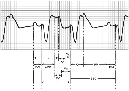
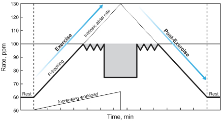
Fig. 7.17 Schematic of the rate response of a DDD pacemaker with pseudo-Wenckebach type block at the upper rate limit (100 ppm). The dotted line represents the intrinsic atrial rate, and the heavy black line represents the ventricular paced rate, assuming pseudo-Wenckebach block as the atrial rate exceeds the maximum tracking rate.
(Modified from Higano ST, Hayes DL, Eisinger G. Sensor-driven rate smoothing in a DDDR pacemaker. Pacing Clin Electrophysiol 1989; 12:922–9, by permission of Futura Publishing Co.)
Portions of Pacemaker Timing Cycles
Atrioventricular Interval
The AVI is initiated by a sensed or paced event (Fig. 7.18A). A ventricular blanking period, usually programmable (ranging from 12 to 125 ms), accounts for the earliest portion of the AVI. If the atrial pacing artifact were sensed by the ventricular sensing circuit, ventricular output inhibition would result. This is termed “crosstalk.” To prevent this, the leading edge of the atrial pacing artifact is masked, or blanked, by essentially turning “off” the ventricular sensing circuit refractory during the very early portion of the AVI (Fig. 7.18B). The blanking period is traditionally of short duration because it is important for the ventricular sensing circuit to be returned to the “alert” state relatively early during the AVI so that intrinsic ventricular activity can inhibit pacemaker output if it occurs before the AVI times out. The potential exists for signals other than those of intrinsic ventricular activity to be sensed and to inhibit ventricular output. Even though the leading edge of the atrial pacing artifact is effectively ignored because of the blanking period, the trailing edge of the atrial pacing artifact can at times persist beyond the blanking period so that it is sensed on the ventricular channel. In a pacemaker-dependent patient, inhibition of ventricular output by crosstalk would result in asystole. A safety mechanism is present to prevent such an outcome.
Fig. 7.18 (A) The atrioventricular (AV) interval should be considered as a single interval with two subportions. The entire AV interval corresponds to the programmed value, i.e., the interval following a paced or sensed atrial beat allowed before a ventricular pacing artifact is delivered. The initial portion of the AV interval is the blanking period. This interval is followed by the crosstalk sensing window. (B) If the ventricular sensing circuit senses activity during the crosstalk sensing window, a ventricular pacing artifact is delivered early, usually at 100–110 ms after the atrial event. This has been referred to as “ventricular safety pacing,” “110 ms phenomenon,” and “nonphysiologic AV delay.” (C) The initial portion of the AVI in most dual-chamber pacemakers is designated as the blanking period. During this portion of the AVI, sensing is suspended. The primary purpose of this interval is to prevent ventricular sensing of the leading edge of the atrial pacing artifact. Any event that occurs during the blanking period, even if it is an intrinsic ventricular event, as shown in this figure, is not sensed. In this example, the ventricular premature beat that is not sensed is followed by a ventricular pacing artifact delivered at the programmed AV interval and occurring in the terminal portion of the T wave. PVC, premature ventricular contraction.
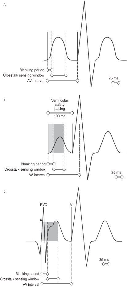
If activity is sensed on the ventricular sensing circuit in a given portion of the AVI immediately after the blanking period (the second portion of the AVI has been called the “ventricular triggering period” or the “crosstalk sensing window”), it is assumed that crosstalk cannot be differentiated from intrinsic ventricular activity. To prevent catastrophic ventricular asystole, in most pulse generators a ventricular pacing artifact is delivered early, i.e., at an AVI of 100–120 ms, although in some pacemakers this interval is programmable for 50–150 ms (Fig. 7.18C). If the signal sensed is indeed something other than a ventricular event, a paced ventricular complex at the abbreviated interval prevents ventricular asystole. If, on the other hand, intrinsic ventricular activity occurs during the crosstalk sensing window of the AVI, the safety mechanism results in delivery of a ventricular pacing artifact within or immediately after the intrinsic beat. This delivery is safe because the ventricle is still refractory, so that no depolarization results from the pacing artifact, and the pacing artifact is delivered too early to coincide with ventricular repolarization or a vulnerable period. This is referred to as “ventricular safety pacing,” “nonphysiologic AV delay,” or the “110-ms phenomenon.” The actual safety pacing duration varies from approximately 70 to 120 ms depending on the device manufacturer and model. One manufacturer does not have “safety pacing” but instead uses a “noise-rejection” interval of 40–60 ms that begins with an atrial pace but is retriggerable and can be retriggered to a maximum of the programmed AV delay, i.e., at the end of that period, even if noise is being detected and retriggering the noise-rejection interval, a pacing output will be delivered.
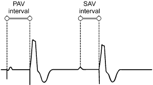
Differential Atrioventricular Interval
If there is a consistent difference between an AVI initiated by a sensed event and those triggered by a paced event, the most likely explanation is a differential AVI. This is an attempt to provide an interatrial conduction time of equal duration irrespective of whether the atrial contraction is paced or sensed. The PV interval initiated with atrial sensing begins at the time of atrial depolarization. Conversely, the AVI initiated with atrial pacing commences with the pacing artifact, not with atrial depolarization. The AVI following a sensed atrial event should therefore be shorter than that following a paced atrial event (Fig. 7.19). The differential between AV and PV is programmable.
Fig. 7.19 Differential atrioventricular (AV) interval timing represents the difference in the AV delay that is dependent on whether it is initiated by an atrial sensed (SAV) or atrial paced (PAV) event.
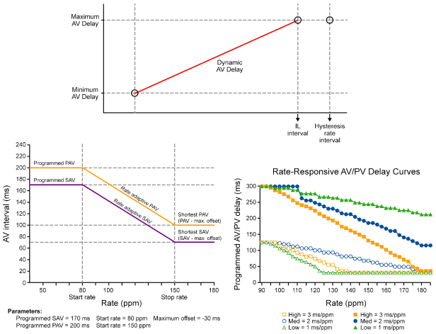
Rate-Variable or Rate-Adaptive Atrioventricular Interval
Most DDDR pacemakers may have the capability of shortening the AVI as the heart rate increases to allow for both tracking and sensor-driven operation.2–4 Rate-adaptive or rate-variable AVI is intended to optimize cardiac output by mimicking the normal physiologic decrease in the PR interval that occurs in the normal heart as the atrial rate increases(Fig. 7.20). The rate-related shortening of the AVI may also improve atrial sensing by shortening the TARP and thereby giving more time for the atrial sensing window. Thus, use of a rate-adaptive AVI permits programming a higher upper rate limit.
Fig. 7.20 Schematic representation of rate-adaptive atrioventricular (AV) interval. As the ventricular rate increases, the AV interval progressively shortens.
There are many variations of rate-adaptive AVI, but linear shortening of the AVI from a programmed baseline AVI to a programmed minimum AVI is common (Fig. 7.21).
Fig. 7.21 Rate-adaptive atrioventricular delay response curves vary between manufacturers. This figure includes a combination of curve responses from various manufacturers.
(Reproduced with permission from: upper, Boston Scientific Corp.; bottom left, Medtronic, Inc.; bottom right, St Jude Medical.)
Atrioventricular Interval Hysteresis
This term is most commonly used to note an alteration of the AVI depending on the patient’s native AV conduction. The term is not used uniformly by manufacturers or caregivers.
Historically, the term “positive” AVI hysteresis was often used to describe a lengthening of the AVI in an effort to maintain intrinsic AV nodal conduction. It basically involves a gradual lengthening of the programmed AVI to determine if an intrinsic ventricular depolarization will occur within a certain interval. If criteria are met, the extended AVI persists unless there is lengthening of the AR or PR interval beyond preset limits, which would once again invoke the programmed AVI (Fig. 7.22). As discussed below and in Chapter 8: Programming, this feature is useful for minimizing the frequency of right ventricular (RV) pacing, thus minimizing the potential adverse hemodynamic effect of RV pacing.2,5,6
Fig. 7.22 Simulated electrocardiographic tracing demonstrating “positive” atrioventricular interval (AVI) hysteresis. The AVI is prolonged to allow intrinsic atrioventricular nodal conduction.
“Negative” AVI hysteresis is usually used to describe a shortening of the AVI in an effort to maintain paced ventricular depolarization (Fig. 7.23). This was at one time felt to have potential hemodynamic benefits for specific patients where it was important to achieve a high percentage of ventricular pacing, and remains useful in cardiac resynchronization devices to ensure that a high percentage of biventricular pacing is achieved.
Fig. 7.23 In the cycle labeled “B,” a sensed R-wave occurs 130 ms after the atrial pulse, i.e., intrinsic ventricular conduction. In the next cycle, the algorithm subtracts the programmed hysteresis value (30 ms) from the measured A-R interval (130 ms), i.e., 130 − 30 = 100 ms AV delay. This is labeled as “1” because it is the first cycle with the shortened AV delay. After 32 cycles, at the shortened AV delay of 100 ms, the programmed AV delay is restored because no R waves have been detected in the AV delay.
(Figure is courtesy of and copyrighted by St. Jude Medical.)
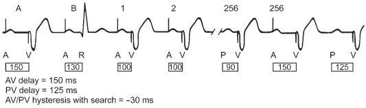
Table 7.2 lists the type of AVI hysteresis by manufacturer with a brief definition and programmable values.
Table 7.2 Manufacturer-specific atrioventricular (AV) hysteresis options.
| Manufacturer | Terminology | Operation |
| Biotronik | AV hysteresis | Encourages intrinsic conduction and is programmable as a “repetitive” or “scan” option. In AV repetitive hysteresis the AVD is extended by a defined value when an intrinsic ventricular beat is sensed. When a paced ventricular event occurs, a long AV delay (AVD) is employed for a programmed number of pacing cycles. If an intrinsic event occurs during one of these cycles then the long AVD remains in operation, but if no intrinsic events occur then the original AVD is resumed. With AV scan hysteresis, after 180 consecutive cycles, the AVD is extended for a programmed number of pacing cycles and if an intrinsic event is detected when it is extended, the longer AVD remains in operation. If an intrinsic event is not detected, the original AVD is resumed. A negative AV hysteresis can be initiated whereby the AVD is decreased by a programmed value after an intrinsic ventricular event. The normal AVD will resume after the programmed number of consecutive ventricular paced cycles has elapsed |
| Boston Scientific | AV search hysteresis | When enabled, the AVI will lengthen periodically for up to eight consecutive cycles. It will remain active as long as the intrinsic PR interval is shorter than the hysteresis AV delay. When the first ventricular pace occurs at the hysteresis AV delay, or when the eight-cycle search expires without sensing an intrinsic ventricular event, the device reverts to the programmed AVD |
| Medtronic | Search AV + | The pacemaker tracks the 16 most recent AV conduction sequences (start with nonrefractory atrial senses or paces in atrial tracking modes and start only with atrial paces in DDI[R] and DVI[R] modes) and adjusts PAV/SAV delays (up by 62 ms or down by 8 ms) to keep intrinsic conducted events in an “AV” delay window that precedes scheduled paced events (by 15–55 ms). The AV delay window is set to promote intrinsic conduction to the ventricles, but ends early enough to avoid fusion or pseudo-fusion beats if pacing is necessary |
| Sorin | Dplus Mode (DDD AV Hyst mode) | Dplus pacing mode is an automatic AVD hysteresis algorithm, designed to promote spontaneous AV conduction. The algorithm uses an automatic extended AVD equal to the PR interval plus a 50-ms window that will allow intrinsic AV conduction (pseudo-AAI). Dplus will switch to DDD during loss of AV conduction (no V sensed event during hysteresis window) and will use the auto adjusted AV delays. While in DDD mode, Dplus periodically (every 100 V-V cycles) extends the AVD to promote the spontaneous AV conduction |
| St. Jude Medical | AV/PV hysteresis with search | The pacemaker will search for intrinsic ventricular conduction every 256 cycles by adding or subtracting the AV/PV hysteresis with search to programmed AV/PV delay. If a ventricular event is not sensed during the extension the programmed AV/PV delay is resumed for another 256 cycles. If it is sensed, the delay remains extended until the interval times out, i.e., no intrinsic event occurs and a ventricular pacing output is delivered. If a “negative” search is programmed then a sensed ventricular event initiates the hysteresis interval being subtracted from the programmed AV/PV delay and the shorter interval will stay in effect for 256 cycles or until another sensed event occurs. (Newest generation of devices have Ventricular Intrinsic Preference [VIP]; see text) |
| Ventricular Intrinsic Preference (VIP) | Search intervals and search cycles are programmable. When three consecutive R waves are sensed during the search interval the algorithm is activated. It is deactivated when the number of ventricular paced events equals the programmed number of cycle counts |
Comparison of Atrial with Ventricular-Based Timing
The way the timing of the pacemaker behaves in response to a sensed atrial and/or ventricular signal varies among manufacturers and among devices from the same manufacturer. Dual-chamber pacemakers may have a ventricular-based timing system, an atrial-based timing system, or a hybrid of these two systems.3,4 The difference between contemporary atrial and ventricular-based dual-chamber pacemakers is of little clinical importance, although the difference may create confusion in interpretation of paced ECGs. Regardless of the timing system used, most manufacturers have modified the timing systems in such a way that the function and ECG manifestations are very similar.
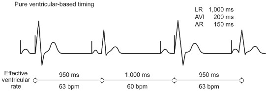
In earlier pacing systems that were pure ventricular-based timing systems, the VA interval was “fixed.” In a pure ventricular-based timing system, a ventricular sensed event occurring during the VA interval resets this timer, causing it to start all over again. A ventricular sensed event occurring during the AVI both terminates the AVI and initiates a VA interval (Fig. 7.24). If there is intact conduction through the AV node after an atrial pacing stimulus such that the AR interval (atrial stimulus to sensed R wave) is shorter than the programmed AVI, the resulting paced rate accelerates. When this occurs at the LRL the rate acceleration would be minimal, e.g., if the pacemaker is programmed to an LRL of 60 ppm (a pacing interval of 1000 ms). With a programmed AVI of 200 ms, the VA interval is 800 ms (VA interval = LRL − AVI). If AV nodal function permits conduction in 150 ms (AR interval = 150 ms), the conducted or sensed R wave inhibits the ventricular output. This, in turn, resets the VA interval, which remains stable at 800 ms. The resulting interval between consecutive atrial pacing stimuli is 950 ms (VA interval + AR interval). This is equivalent to a rate of 63 ppm, which is slightly faster than the programmed LRL (Fig. 7.24). When a native R wave occurs – e.g., a ventricular premature beat during the VA interval – the VA interval is also reset. The pacemaker timing cycle is reset, and the result is a rate defined by the sum of the VA interval and the AVI. This escape interval is therefore equal to the LRL. In both cases, the sensed ventricular event, an R wave, regardless of where it occurs, resets the VA interval.
Fig. 7.24 With ventricular-based timing in patients with intact atrioventricular (AV) nodal conduction after atrial (AR) pacing, the sensed R wave resets the ventriculoatrial (VA) interval. The base pacing interval consists of the sum of the AR and the VA intervals; thus, it is shorter than the programmed minimum rate interval.
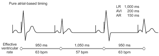
In contrast, in a pure atrial-based timing system, the AA interval is fixed. As long as there is stable LRL pacing, there will be no discernible difference between the two timing systems.
In a system with pure atrial-based timing, a sensed R wave occurring during the AVI inhibits the ventricular output, but does not alter the basic AA timing (Fig. 7.25). Hence, the rate stays at the programmed LRL during effective single-chamber atrial pacing. When a ventricular premature beat is sensed during the VA interval, the timers are also reset, but now it is the AA interval rather than the VA interval that is reset. The pacemaker counts out an AA interval and then adds the programmed AVI, attempting to mimic the compensatory pause commonly seen in normal sinus rhythm with ventricular ectopy. For example, if the pacemaker was programmed to 60 ppm, 1000 ms cycle length, and an AV delay of 200 ms, AV sequential pacing occurs and is followed by an atrial paced event at 1000 ms from the previous paced atrial event. However, if intrinsic ventricular conduction occurs at 150 ms, i.e., truncates the AV delay by 50 ms, it would result in an effective ventricular rate of 950 ms, or 63 ppm, i.e., an 800-ms VA interval plus a 150-ms AR interval. The next paced atrial event is still delivered at 1000 ms after the preceding paced atrial event, as defined by atrial-based timing. This time, the programmed AVI expires and a paced ventricular complex occurs. This results in an effective ventricular rate of 850 ms; the VA interval, which was lengthened by 50 ms because of the preceding intrinsic ventricular activity, and the 200-ms AVI, for a cycle length of 1050 ms, or 57 ppm.
Fig. 7.25 With atrial-based timing in patients with intact atrioventricular nodal conduction after AR pacing, the sensed R wave inhibits the ventricular output but does not reset the basic timing of the pacemaker. There is AR pacing at the programmed base rate. ARI, interval from paced atrial event to intrinsic QRS; AVI, atrioventricular interval; LR, lower rate limit.
Most contemporary pacemakers are hybrid timing systems. The best source of information for the timing cycle of a specific pulse generator is the technical manual for the device in question. A summary of the timing systems in the most recent generation of pacemakers from each company is shown in Table 7.3.
Table 7.3 Summary of the timing systems in the most recent generation of pacemakers from each company.
Stay updated, free articles. Join our Telegram channel

Full access? Get Clinical Tree


