Fig. 4.1
3D image of a normal mitral valve seen en face from the classic surgeon’s view. The image was acquired with the full volume mode. The aortic valve (AV) is seen at the 12 o’clock position above the mitral valve. The anterolateral commissure (AL) and the posteromedial commissure (PM) are indicated. The posterior mitral leaflet is divided into three segments or scallops (P1 lateral, P2 middle and P3 medial). Similar corresponding areas within the anterior mitral leaflet are also identified and are part of the nomenclature described by Carpentier [3]
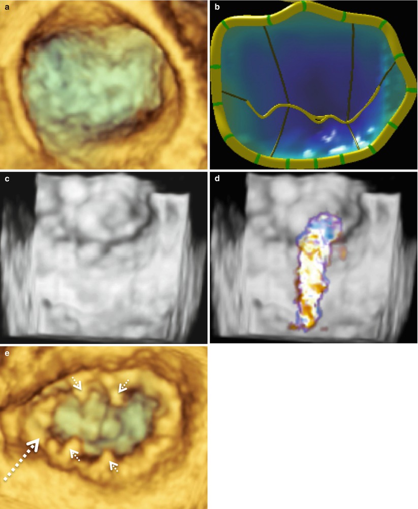
The most common MV pathology requiring surgical intervention is mitral regurgitation (MR) due to leaflet prolapse. Figure 4.2a–d shows 3D images of a MV from a patient with P2 leaflet prolapse. As demonstrated in these images, there is prolapse throughout the valve; however, the majority of the prolapse occurs in the P2 region. This is evident from the 3D MV model and is consistent with an anterior directed MV regurgitant jet, which originated from the P2 region (Fig. 4.2d). This valve was repaired with P1-P2 and P2-P3 cleft (indentation) closures, along with a “haircut” resection of P2 (radial excision of the P2 tip) with reattachment of the remaining P2 chords to the P2 leaflet leading edge. A 36 mm Cosgrove Flexible Annuloplasty Band (Edwards Lifesciences, Irvine, Calif.) was then implanted (Fig. 4.2e). Imaging of a MV from a patient with a P3 prolapse is shown in Fig. 4.3. In this case, the P3 prolapse is identified easily both in the acquired image (Fig. 4.3a) and the 3D MV model (Fig. 4.3b). This valve was repaired with a P3 commissuroplasty and implantation of a 37 mm ATS Simulus Flexible Annuloplasty band (Medtronic, Minneapolis, MN) (Fig. 4.3c).
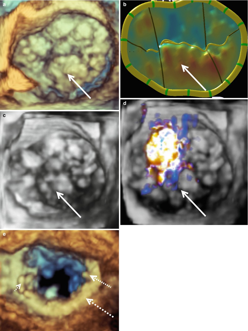
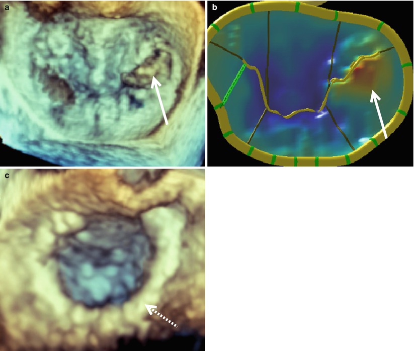
Fig. 4.2
A typical P2 mitral valve prolapse seen from the surgeon’s view. Image (a) was acquired with live 3D zoom. A corresponding model of the mitral valve is shown (b) along with color full volume images with the color suppressed (c) and with color on (d). A live 3D zoom image of the repaired mitral valve is shown in (e). The P2 prolapse is indicated by the solid arrow in each picture. The annuloplasty ring is indicated by the large dashed arrow and prominent sutures by the small dashed arrows
Fig. 4.3
A typical P3 mitral valve prolapse seen en face from the surgeon’s view. Prior to repair the 3D mitral valve image was acquired with live 3D zoom (a). The corresponding model of the mitral valve is shown (b) along with a live 3D zoom image of the repaired valve (c). The solid arrows indicate the prolapsed P3 segment. The annuloplasty ring is indicated by the dashed arrow
Figure 4.4 illustrates a patient requiring an anterior MV leaflet repair. This patient had prolapse of the A3 segment, which is demonstrated in both the acquired image (Fig. 4.4a) and the mitral valve model (Fig. 4.4b). This valve was repaired with an A2 to A3 chord transfer and insertion of a 35 mm ATS Simulus Flexible Annuloplasty Band (Fig. 4.4c). Multiple prolapsing MV segments can be seen in Fig. 4.5a–c. The entire posterior leaflet appears both to billow (leaflet body) and prolapse (coapting edge). In addition, anterior leaflet segments A1 and A2 appear to prolapse. Figure 4.5d shows a large central jet and at least one other jet originating from the anterolateral commissure. This valve was repaired successfully with a P2 “haircut” procedure, a P3 quadrangular resection, P1-P2 and P2-P3 cleft closures, and insertion of 31 mm ATS Simulus Annuloplasty Band (Fig. 4.5e).
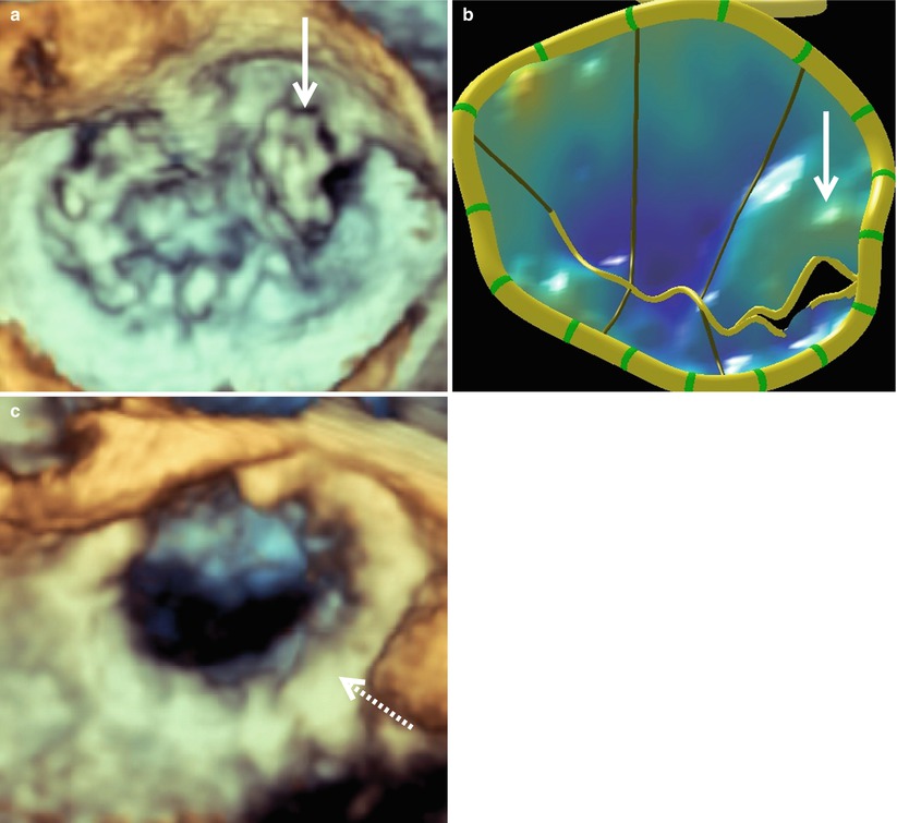
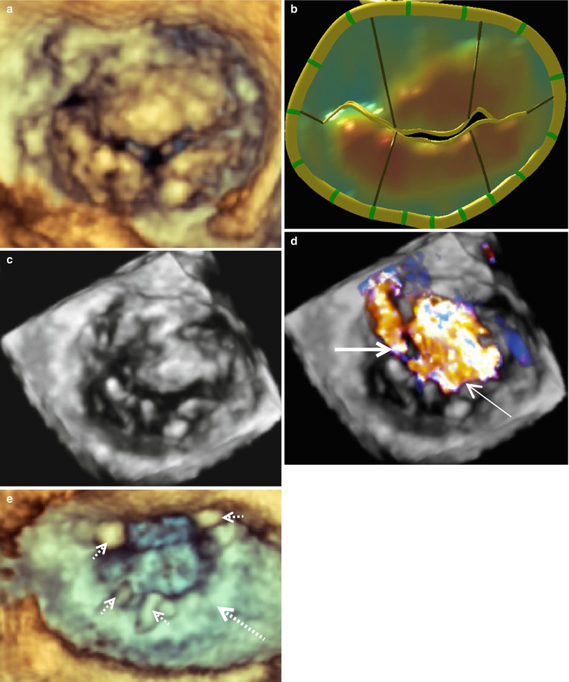
Fig. 4.4
A3 mitral valve prolapse as seen en face from the surgeon’s view. Prior to repair a mitral valve image was acquired with live 3D zoom (a). A model of the mitral valve is shown (b) along with a live 3D zoom image of the repaired valve (c). The solid arrows indicate the prolapsed A3 segment. The annuloplasty ring is indicated by a dashed arrow
Fig. 4.5
Multiple prolapsing segments of an insufficient mitral valve as seen en face from the surgeon’s view. Image (a) was acquired with live 3D zoom. A corresponding model of the mitral valve is shown (b) along with color full volume images with the color suppressed (c) and with color on (d). A regurgitant jet originating from the anterolateral commissure is indicated by the thick solid arrow and a large central regurgitant jet is indicated with the thin solid arrow. A 3D zoom image of the repaired mitral valve is shown in (e). The annuloplasty ring is indicated by the large dashed arrow and the prominent sutures by the small dashed arrows
One of the most complex types of mitral pathology to repair is the myxomatous bi-leaflet prolapsing valve associated with Barlow’s disease. This type of degenerative valve is characterized by excessive leaflet tissue with myxoid appearance and leaflet billowing, leading eventually to the development of excessive chordal elongation and severe bileaflet prolapse. Today, we see various stages of this type of degeneration with some valves having all segments prolapsing above the annular plane. Images obtained from RT-3D-TEE allow accurate identification of severely diseased areas responsible for regurgitation in these patients. For example, images taken from a patient with a typical Barlow’s type valve are shown in Fig. 4.6a–d. These images demonstrate clearly that the most severe prolapse occurs in the area of P2 with two associated regurgitant jets. One jet is directed posteriorly and the other is directed anteriorly (Fig. 4.6d). This valve was repaired with a triangular resection of P2 and placement of a 36 mm Cosgrove Flexible Annuloplasty Band (Fig. 4.6e). Often small levels of prolapse may not need direct surgical intervention, as the annuloplasty will reduce 1–3 mm of anterior leaflet prolapse to coapt sufficiently with the posterior leaflet.
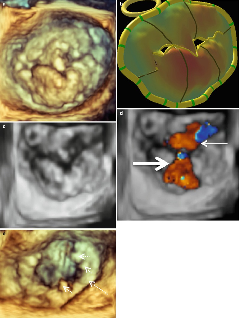
Fig. 4.6
A typical Barlow’s mitral valve seen en face from the surgeon’s view. Image (a) was acquired with live 3D zoom. A corresponding model of the mitral valve is shown (b) along with color full volume images with the color suppressed (c) and with color on (d). An anteriorly directed regurgitant jet is indicated with the thin solid arrow. A posteriorly directed regurgitant jet is indicated with the thick solid arrow. A live 3D zoom image of the repaired mitral valve is shown in (e). The annuloplasty ring is indicated by the large dashed arrow and the prominent sutures by the small dashed arrows
It is important to distinguish a flail MV leaflet from a prolapsing one. This is done routinely by 2D-TEE; however, flail leaflets become even more apparent and detailed with 3D-TEE. Figure 4.7a shows a MV with two ruptured cords in the P2 -P3 region. This valve was repaired with a P2 triangular resection and a 35 mm ATS Simulus Flexible Annuloplasty Band (Fig. 4.7b). The MV from another patient with a P2 flail leaflet is shown in Fig. 4.7c. This patient had one ruptured cord and much more posterior leaflet redundant tissue, necessitating a more complex repair. This valve was repaired successfully with a trapezoidal P2 resection, imbrication of P2 chords to give full support across the leading edge of P2, a P1-P2 cleft closure, a secondary chord transfer to the leading edge of A2, and placement of a 37 mm ATS Simulus Flexible Annuloplasty Band (Fig. 4.7d). Finally, Fig. 4.7e shows an A1 MV flail segment. This valve could not be sucessfully and was replaced.
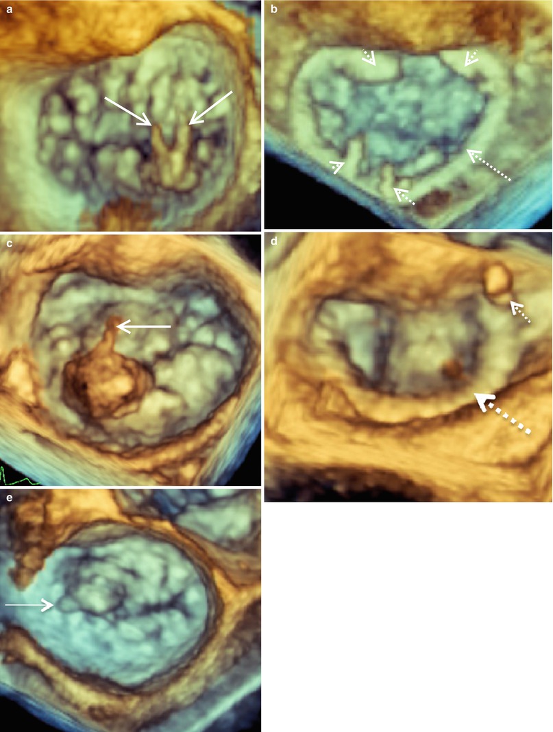
Fig. 4.7
3D imaging of mitral valves from three patients with flail P2 (a, c) and A1 (e) segments demonstrated en face from the surgeon’s view. Mitral valve images were acquired with live 3D zoom before (a, c, e) and after repair (b, d). The solid arrows indicated ruptured chordae. The annuloplasty rings are indicated by the large dashed arrows and the prominent sutures by the small dashed arrows
Ischemic MR often represents a challenge to recognize, characterize, and repair, particularly in patients receiving concomitant coronary artery bypass grafting. Classic restrictive ischemic MR (Type IIIb) results from lateral displacement of the papillary/chordal complex during systole with resultant P3 tethering and asymmetric annular dilatation. This results in a posterior directed regurgitant jet and is associated with left ventricular wall motion abnormalities. A mitral valve from a patient with type IIIb ischemic MR and a characteristic posteriorly directed regurgitant jet is illustrated in Fig. 4.8. The MV in this patient was repaired with the placement of a 34 mm ATS Semi Rigid Full Annuloplasty Ring (Fig. 4.8e). Conversely, Fig. 4.9a–d shows an example of central ischemic MR, which is associated with global ischemia and concomitant ventricular dilatation. The 3D MV model is particularly useful in this case as it demonstrates how the anterior and posterior tethered leaflets are distracted down and apart with reference to the annular plane (Fig. 4.9b). In this case tethering resulted from lateral displacement of both papillary muscles with systole. Images obtained with color full volume imaging show the classic central regurgitant jet (Fig. 4.9d). Repair of this valve was accomplished with a 30 mm Carpentier Edwards Physio Rigid Annuloplasty Ring (Edwards Lifesciences Corporation, Irvine, CA).