Chapter 2 Thoracic imaging
ADULTS
CHEST RADIOGRAPHY AND OTHER TECHNIQUES
Different types of chest radiograph
The majority of chest radiographs are obtained in the main radiology department. The radiograph is obtained with the patient standing erect. Patients who are immobile or too ill to come to the main department have a chest radiograph performed using a mobile machine (portable film); the resulting radiograph differs from a departmental film in terms of projection, positioning, exposure and film used and is therefore not strictly comparable with a conventional posteroanterior (PA) film. Other types of chest radiograph are the lateral, lordotic, apical and decubitus views; these are generally taken in the main department.
Factors influencing the quality of a chest radiograph
The sensitivity of film to direct X-ray exposure is very low and if film were used alone as the image receptor, this would result in a prohibitively large X-ray dose to the patient. Intensifying screens made of phosphorescent material are positioned on the inside of the cassettes and they convert the incident X-ray photons into visible light, which is recorded by the adjacent film. These phosphor screens are composed of either calcium tungstate or a rare-earth-containing compound. Rare- earth phosphors emit more light in response to X-ray photons and therefore less radiation is necessary to produce the image. Similarly, improvements in the quality of X-ray film have also occurred over the years. Standard film emulsions tend to lack detail in the relatively under- or overexposed areas of the radiograph and newer emulsions have been developed so that detail is similar in all areas of the chest radiograph. The choice of film–; combination has a crucial influence on the quality and ‘look’ of the radiograph produced. Further variations may result from film-processing problems.
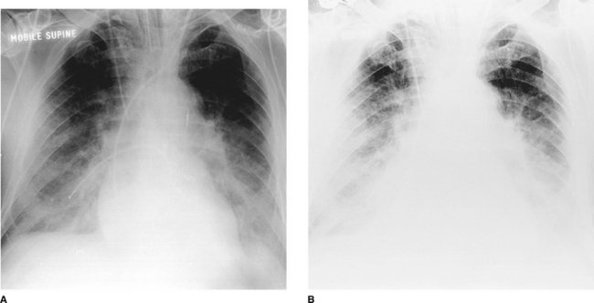
In the intensive care setting, portable chest radiographs are often taken in less than ideal conditions. Multiple tubes, lines and dressings in conjunction with an immobile, supine patient and the use of a mobile low- kilovoltage machine often result in suboptimal radiographs. One approach to this is the development of phosphor plate technology, which is ultimately expected to replace conventional film–; radiography. The phosphor plate is placed inside a conventional cassette and stores some of the energy of the incident X-ray photons as a latent image (the image produced on a film or phosphor plate before development). The plate is scanned with a laser beam and the light emitted from the ‘excited’ latent image is detected by a photomultiplier. Thereafter this signal is processed in digital form. This digital image may be viewed either on a television monitor or on film (on which it has been laser printed). The great advantage of this system is that it can retrieve an image of diagnostic quality from a suboptimal exposure. Similar gross over- or underexposure would result in a non-diagnostic conventional radiograph. Manipulation of the digital image, particularly ‘edge enhancement’, aids the detection of linear structures such as the edge of a pneumothorax or central venous catheters (Fig. 2.1). With the advent of picture archiving and communication systems (PACS), which enable storage and transfer of digital images, many radiology departments are now ‘filmless’, with images available to view simultaneously on monitors throughout the hospital.
Other techniques
Ultrasonography
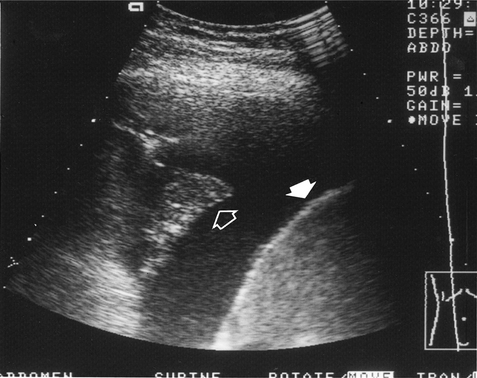
High-frequency sound waves do not traverse air and the use of this technique is therefore limited in the chest. It is mainly used for cardiac imaging (echocardiography) and has become an essential technique in the investigation of patients with valvular and ventricular function problems. Outside the heart, ultrasonography is very useful in distinguishing between fluid above the diaphragm (pleural effusion, Fig. 2.2), fluid below the diaphragm (subphrenic) and pleural thickening. Chest radiography often cannot differentiate between pleural fluid and thickening with any certainty. Ultrasound can also be used to guide the placement of a percutaneous drain into a pleural effusion or biopsy peripheral lung lesions that are in contact with the pleura.
Computed tomography
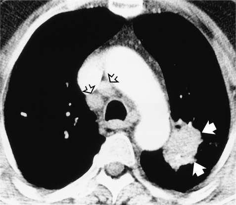
Because of the cross-sectional nature of CT, it can accurately localize lesions seen on only one view on plain chest radiographs. The superior contrast resolution of CT allows superb demonstration of mediastinal anatomy (e.g. lymph nodes and vessels) (Fig. 2.3) as well as calcification within a pulmonary nodule. Highly detailed thin sections of the lung parenchyma can also be obtained, allowing the complex morphology of many interstitial lung diseases to be more accurately defined. The disadvantages of CT are its relatively high cost and increased radiation exposure to the patient compared with chest radiography.
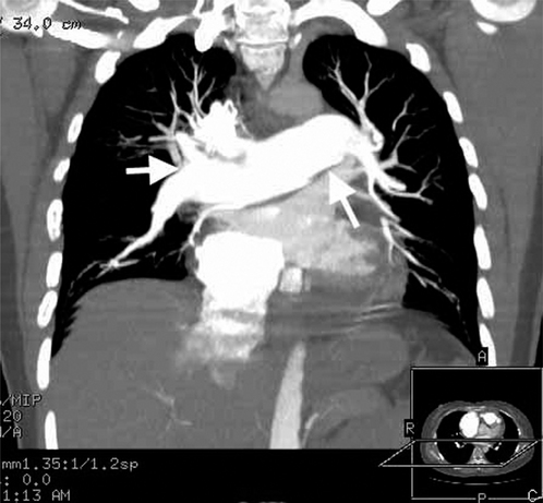
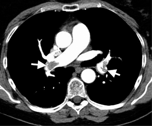
Whereas conventional CT scanning involves alternating table movement through the gantry with exposure, helical or volumetric CT involves simultaneous table movement and X-ray exposure. The technique allows faster scan times and advantages are the elimination of respiratory artefacts, minimization of motion artefacts and production of overlapping images without additional radiation exposure. Helical (spiral) CT is so named because the X-ray can be thought of as tracing a helix or spiral curve on the patient’s surface. Multiple rows of detectors are used in the newer helical CTs, so-called multidetector CT (MDCT). The technique allows viewing of images in multiple planes (Fig. 2.4) and, due to the very fast acquisition times, is increasingly used to evaluate cardiac structures such as the coronary arteries. Helical CT is also now commonly used to demonstrate pulmonary emboli, as accurate timing of a bolus of intravenous contrast allows optimal enhancement of the pulmonary arteries (Fig. 2.5).
Common indications for CT of the chest
Magnetic resonance imaging
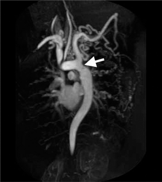
The physical principles of magnetic resonance imaging (MRI) are more complex and very different from those of CT scanning. The equipment consists of a sliding table on which the patient lies within the bore of a large magnet. A combination of the intense magnetic field and a series of radiofrequency waves produces an alteration in the alignment of protons (mostly in water) resulting in the emission of different signals which are detected and subsequently analysed for their intensity and position by a computer. The major advantages of MRI are that images may be obtained in any plane without the use of ionizing radiation. The disadvantages are its inability to produce detailed images of the lung, cost and reduced acceptability to patients because of the claustrophobic bore of the magnet. There are also important contraindications such as permanent cardiac pacemaker devices. Its application to chest imaging is limited at present but the technique is good for imaging chest wall lesions, the great vessels (Fig. 2.6) and the heart.
Radionuclide imaging
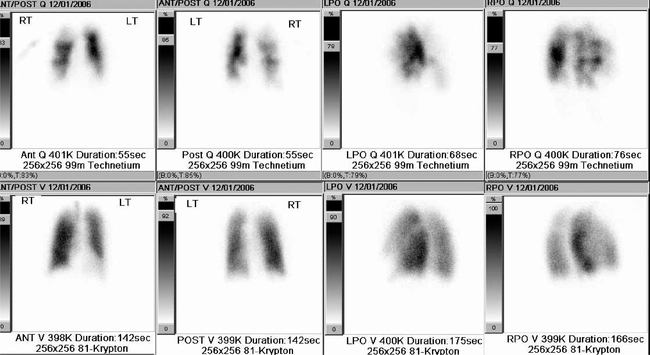
Ventilation–perfusion ( ) scanning is the commonest radionuclide study of the lungs. It is primarily used to investigate suspected pulmonary embolus. Perfusion is assessed by intravenous injection of minute particles labelled with technetium-99m, a radioactive tracer. These particles become temporarily lodged in a very small proportion of capillaries within the lung and the emitted radiation is detected by a so-called gamma camera. Ventilation is assessed by the inhalation of inert gases that have also been labelled with a radioactive tracer. The ventilation and perfusion images are then compared to see if there are any areas of mismatch (Fig. 2.7). Increasingly CT is used to investigate patients with possible pulmonary embolus, as
  scanning is more difficult to interpret in patients with coexisting lung disease such as asthma. In addition, the tracers have a short period of radioactivity after they are produced of a few hours and therefore scanning late at night and at weekends may be difficult.
Positron emission tomography
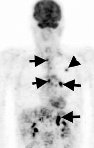
Positron emission tomography (PET) is also a form of radionuclide imaging. A detector can pinpoint where there is uptake of tracer accurately within the body. PET highlights areas that are very metabolically active, such as cancers, but also infection and inflammation. Access to this type of costly scanner is becoming more widespread, and it is mainly used in the chest for assessment of disease spread of lung cancer to lymph nodes and sites outside the chest (Fig. 2.8). The images may be fused with CT images (PET/CT) to give a very precise location of tumour spread.
Interventional procedures
Percutaneous needle biopsy
Percutaneous needle biopsy of a pulmonary or mediastinal mass to provide a histological specimen is usually performed in patients in whom a bronchoscopic biopsy has failed or a thoracotomy is inappropriate. Different types of needle are used and the complication rate (pneumothorax and haemoptysis) bears some relation to the site of the lesion, the size of the needle and the number of attempts to obtain tissue. Contraindications to the procedure include any patient with poor respiratory reserve unable to withstand a pneumothorax, pulmonary arterial hypertension and a previous contra- lateral pneumonectomy.
THE NORMAL CHEST
Anatomy
On the normal posteroanterior radiograph (Fig. 2.9) the following structures can be identified:
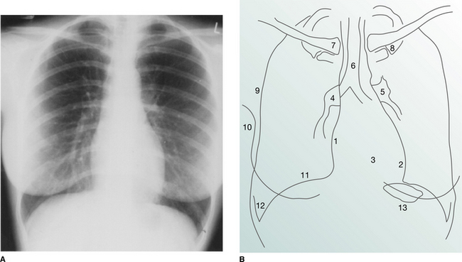


The heart and mediastinum
The mediastinum consists of the organs and soft tissues in the central part of the chest. These comprise the trachea, aortic arch and great vessels, superior vena cava and oesophagus. In children the thymus gland is a prominent component. On the two-dimensional chest radiograph these structures are superimposed and cannot be clearly distinguished from each other. The mediastinum is conventionally divided into superior, anterior, middle and posterior compartments. While the boundaries of the latter three are arbitrary, it is usual to divide the mediastinum into equal thirds. The superior mediastinum is that portion lying above the aortic arch and below the root of the neck.
The hila
Abnormalities of the hilar shadows in the form of increased density or abnormal configuration are usually the result of lymph node or pulmonary artery enlargement. The detection of subtle hilar abnormalities is difficult and requires experience and knowledge of the many outlines that the hila may assume in normal individuals.
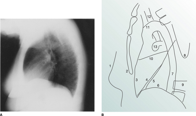
The lateral view
It is conventional to read the lateral film (Fig. 2.10) with the heart to the viewer’s left and the dorsal spine to the right, irrespective of whether the film is labelled ‘right’ or ‘left’. The chamber of the heart that touches the sternum is the right ventricle. Behind and above the heart lies lung, the density of which should be the same both behind the heart and behind the sternum. As the eye travels down the spine, the vertebral column should appear increasingly transradiant or ‘dark’ (Fig. 2.10A); the loss of this phenomenon suggests the presence of disease in the posterobasal segments of the lower lobes. In the middle of the lateral film lie the hilar structures with the main pulmonary artery anteriorly. The aortic arch should be easily identified but only a variable proportion of the great vessels is visible depending on the degree of aortic unfolding. The brachiocephalic artery is most frequently identified arising anterior to the tracheal air column. The left and right brachiocephalic veins form an extrapleural bulge behind the upper sternum in about a third of individuals.
Useful points in interpreting a chest radiograph
Radiographic projection.
A judgement as to whether a radiograph is AP or PA can be made from the following evidence:


