Fig. 28.1
Episode marked as VT/VF. The far-field electrogram (A) is present on the top, the near-field ventricular sense channel (V) is present in the middle tracing, and the marker channel is on the bottom
Noise and artifacts can lead to oversensing and cause inappropriate ICD therapies; they can be classified into different types:
External noise (e.g., magnetic interference) usually present on all sensing channels, constant and regular, with high frequency (~50–60 Hz)
Myopotential noise with high frequency and low and constant amplitude, which can vary with respiration
Internal noise, due to problem in the lead conductors with high-frequency and highly variable amplitude, which occurs intermittently, separated by periods of isoelectric baseline and typically on one lead/channel
The episodes marked as VF are likely to be an artifact with the characteristics of high amplitude and low frequency, not constant but intermittent, which suggest a problem in the integrity of ventricular lead.
Figure 28.2 shows another episode labeled as VF, inappropriately treated with ATP, and capacitors charging subsequently aborted; in reality it is not a real VF but an oversensing phenomenon from double T-wave counting.
Fig. 28.2
VF episode secondary to T-wave oversensing (top). Capture test (bottom)
The patient was called for an ambulatory visit. During ICD interrogation, the anomalies already showed with remote monitoring were confirmed, the usual tests were performed, and the parameters of sensing, pacing, and ventricular lead impedance (sensing 11.7 mV, impedance pacing 460 Ω, shock impedance 50 Ω) were evaluated. It was noticed that each paced ventricular beat was followed by artifacts recorded on ventricular channel; that confirmed the malfunction of the device (Fig. 28.2). Furthermore the noise could be reproduced by isometric maneuvers and with pocket manipulation.
After confirmation of ICD system malfunction, the patient was hospitalized in the cardiology clinic.
Medical History and Cardiovascular Risk Factors
No cardiovascular risk factor. Hiatal hernia. Thalassemia trait
Allergies
No allergy is referred by the patient.
Social History
The patient works as an employer. Does not smoke or drink alcohol. He never used illicit drugs.
Medications
He was not on any medication.
Vital Signs
Temperature 36.4 °C, heart rate 75 bpm, blood pressure 120/80 mmHg, respiratory rate 16 breaths per minute, and oxygen saturation in ambient air 97 %
Physical Examination
Weight 70 kg, height 167 cm, and estimated body mass index (BMI) of 25.
General: alert, awake, and oriented.
Skin: normal in appearance, texture, and temperature; no rashes; no lesions; no erythema.
Head, eyes, ears, nose, and throat: normal.
Neck: no abnormal adenopathy in the cervical or supraclavicular areas. Thyroid gland is normal without masses. No carotid bruit and no jugular venous distention.
Cardiovascular: Regular rate and rhythm; S1 and S2 normal; no murmurs, rubs, or gallops heard; point of maximal intensity nondisplaced and nonsustained; and no hepatojugular reflux.
Lungs: Lungs are clear to auscultation and percussion bilaterally and no alterations in tactile fremitus.
Abdomen: The abdomen is symmetrical without distention; bowel sounds are normal in quality and intensity in all areas. No masses or splenomegaly noted; liver span is 6 cm by percussion.
Extremities: No cyanosis, clubbing, or edema noted. Peripheral are normal in all areas.
Neurologic: Cranial nerves II–XII are normal. Motor and sensory examination of the upper and lower extremities is normal. Reflexes are normal and symmetrical bilaterally in both extremities.
Routine EKG at Rest (Fig. 28.3)
Fig. 28.3
EKG. Conclusions: sinus rhythm, normal atrioventricular conduction, type 1 Brugada syndrome pattern saddleback in V2
Conclusions: sinus rhythm, normal atrioventricular conduction, and type 1 Brugada syndrome pattern saddleback in V2.
All the routine laboratory tests were performed, including complete blood count, liver and renal functions, electrolytes, thyroid function, and lipid concentrations—all resulted normal.
Echocardiography
Tricuspid Aortic Valve with Normal Valve Opening. Normal size of aortic bulb, ascending aorta, aortic arch, and abdominal aorta. Left atrium of normal size (LA diameter M-mode = 30 mm, area 14 cm2). Right atrium was normal (area 4c = 14 cm2). Prolapse of the anterior mitral leaflet. The tricuspid valve was normal.
Normal Dimensions and Thicknesses of the Left Ventricle. Normal contractile function (ejection fraction 60 % with Simpson’s biplane method) and normal wall motion. Right ventricle of normal size and with normal contractile function (TAPSE = 29 mm). Inferior vena cava of normal size (13 mm), with normal collapse during inspiration. The pericardium is normal. Color Doppler: mild mitral regurgitation. Normal diastolic function. Minimal tricuspid regurgitation. PAPs about 20 mmHg.
There are a lot of factors that should be weighed in the management of a failed ICD lead.
First, the suspected mechanism of lead failure should be evaluated; for this reason to exclude a macroscopic failure of the lead, a fluoroscopy was made, which showed no images related to fractures or insulation defects of the conductors.
Given the sensing defect of the ventricular lead, we have reprogrammed sensitivity parameters, in order to reduce the oversensing phenomenon; when sensitivity parameters of an ICD are changed, it is always advisable to perform a defibrillation threshold test (DFT).
During the DFT (Fig. 28.4) after the first shock at 2 J to induce VF, some noise entered the ventricular channel hiding the real VF; when the noise has stopped, the VF signal was very low and unclassified beats were recorded. The shock was effectively delivered late by the device, and during the pacing post-shock, every paced beat was followed by noise and ICD began to recharge already the capacitors. To avoid that other inappropriate shocks were delivered, ICDs were turned off.
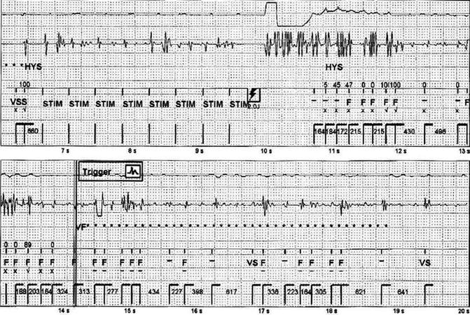
Fig. 28.4
Defibrillation threshold test
What Are the Treatment Options in Case of Malfunction of an ICD Ventricular Lead?
1.
Add a new pace/sense lead alone, leaving in place the old lead, if the shock circuit is working correctly. This may be the appropriate strategy in older patients, patients with multiple comorbidities, or patients for whom lead extraction is prohibitively high risk. The disadvantages of adding new leads without removal of the failed leads include multiple leads crossing the tricuspid valve, lead-to-lead interaction, and an increased risk of future lead-related problems. If lead extraction became necessary in the future, the complexity and risks would be higher with more leads.
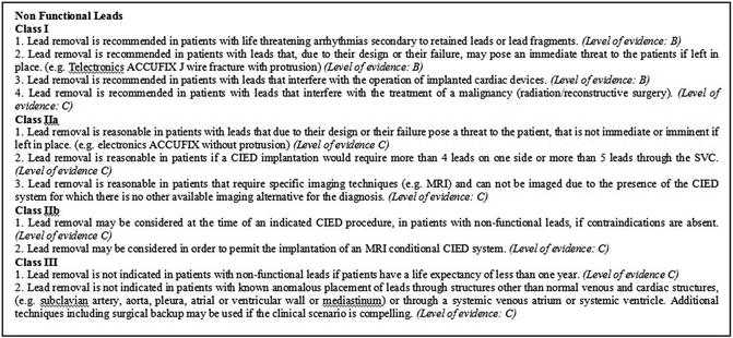
2.
Lead extraction. The 2009 Heart Rhythm Society consensus recommendations for the extraction of a nonfunctional, noninfected ICD lead [1] are reported in Fig. 28.5. The extraction procedure has a high morbidity with possible fatal complications (cardiac or vascular avulsion, cardiac tamponade, pulmonary and systemic embolism, retained ICD lead fragments, lead dislodgement, or damage to other existing leads). Passive fixation leads and dual-coil leads may be more difficult to extract because of increased adhesions.
Management in every case needs to be individualized.
In our case, given the young age of the patient, with no comorbidities, with a long life expectancy, and with an average time from the implantation of the lead, we decided to proceed with the extraction. The procedure was performed under local anesthesia by an interventional cardiology in the electrophysiology lab with a cardiac surgeon on standby. After lead isolation with an excimer laser sheath system, its removal was performed without complications.
Few days later, the patient underwent implantation of a subcutaneous ICD (S-ICD, Cameron Health). This new type of cardioverter defibrillator was approved in 2012 by the FDA; it is implanted subcutaneously without using intracardiac and intravascular leads.
The indications for implant of an S-ICD are the same as a transvenous ICD, excluding the need for pacing for bradycardia and recurring ventricular tachycardia (VT) that is reliably terminated with antitachycardia pacing (ATP).
For these reasons, it is therefore particularly indicated for young patients, with an active lifestyle and a long life expectancy, at risk of sudden cardiac death due to ventricular tachyarrhythmias, as in the genetic arrhythmogenic syndromes (Brugada syndrome, long and short QT syndrome, and other channelopathies).
After the implantation, a chest X-ray was performed that confirmed the correct placement of the S-ICD system (Fig. 28.6).
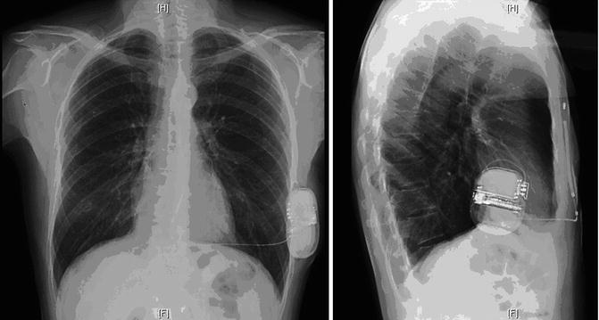
Fig. 28.6
Chest X-ray postimplantation of the S-ICD (posteroanterior and lateral views)
The patient was discharged in stable condition.
Conclusion
Inappropriate therapies delivered from the ICD, due to the malfunction of ventricular lead, treated with transvenous lead extraction and implant of the new S-ICD. Home monitoring was crucial for early defect detection.
28.2 Home Monitoring
Introduction
Routine device follow-up assessment at regular intervals is required after implant of an electronic device (PMK or ICD) [2]. The purpose of these assessments is to evaluate the patient and the device control. Traditionally, device follow-up clinic is designated to realize these assessments. In the last years, a new technology such as the remote monitoring (RM) is developed and permits surveillance and device assessment from any location of the patient. RM is important to facilitate early diagnosis of arrhythmia and evaluate earlier than in-office visit problems with the device or leads. Now, in the international guidelines, RM of implantable devices has been indicated as a new standard for patient follow-up, and it has been defined as an alternative to the large part of scheduled follow-up visits [3].
Types of Remote Monitoring Systems
Home Monitoring™ (Biotronik)
It was introduced first in 2001. This technology automatically permits the transmission of data on a daily basis at fixed intervals and soon after a clinically relevant event has occurred. It is wireless and does not require patient action. The surveillance parameters can be individualized. This function of the system can be summarized in three steps:
1.
The first step is the communication between the implanted generator and the patient device, named CardioMessenger (CM). On the scheduled time, the patient must be from 20 cm to 2 m far from the CM to ensure successful transmission.
2.


The second step is the delivery of the CM message to the service central, via GSM/GPRS cellular. A specific website shows the device periodical report of the Biotronik Home Monitoring® system that includes the intracavitary EKG. At the top, the mark channel is visualized, and at the bottom, the electrocardiograms are observed. The system automatically performs the following transmissions: (1) Every 24 h, at a physician-scheduled time, the device sends a transmission containing the data recorded along the last 24 h that is forwarded by CM to the service center. (2) A message is immediately sent when a serious cardiac event or change happens in the device parameters.
< div class='tao-gold-member'>
Only gold members can continue reading. Log In or Register to continue
Stay updated, free articles. Join our Telegram channel
Full access? Get Clinical Tree
