1 The Pediatric Transthoracic Echocardiogram
Imaging Planes
Key Points
• Imaging planes may be unique to each individual patient; for example, in the setting of a newborn with a diaphragmatic hernia, the typical views may be obtained from nonstandard locations on the chest because the heart is displaced significantly within the thoracic cavity.
• Best practice is to obtain two-dimensional (2D) imaging before spectral or color flow Doppler. This allows for an anatomic frame of reference before the addition of physiologic data.
• Before acquisition of Doppler data, an anatomic 2D image should be recorded to document the curser position.
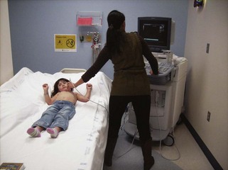
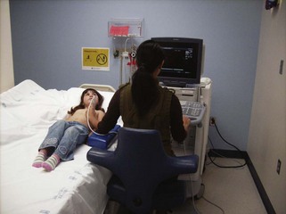
• Ergonomics should be considered at all times (Figs. 1-1 and 1-2). Make yourself comfortable. Based on patient age, location where study is being performed, and other environmental conditions (i.e., patient instrumentation, patient body position restrictions, lighting conditions), accommodations may be required to optimize image acquisition. This can make the difference between an exam that shows the pathology at a quality level, which allows for an accurate diagnosis, and a study that is incomplete, requiring subsequent imaging or resulting in incorrect management decisions.
• Standard adult imaging planes and views apply. However, variations of these views are required to optimally image atypical anatomy and cardiac position.
• Nonstandard views are frequently used to assess complex anatomy and track the route of extracardiac anatomic structures and vessels that cannot be seen in a single view. For example, a right ventricle (RV)-to-pulmonary artery (PA) conduit may require evaluation in three separate imaging planes to obtain a complete assessment: parasternal to visualize the mid-conduit, apical to image the conduit origin, and subcostal to image the distal end at the pulmonary branch bifurcation.
• With the use of nonstandard views, it is critical to acquire confirmatory points of reference, to obtain longer clips, and to demonstrate anatomic relationships via sweeps from one plane to the next. This will allow the interpreting physician the opportunity to render the most accurate diagnosis.
• Use annotation on the clip to communicate findings and relay information as to the intent of clip acquisition (Table 1-1, Figs. 1-3 to 1-10).
| Window | View | Basic Anatomy Viewed |
|---|---|---|
| Left parasternal | LV long axis | LV |
| Slice 2 in Figure 1-3 | Ventricular septum | |
| MV (and supporting structures) | ||
| AV | ||
| LA | ||
| CS | ||
| Proximal aortic root | ||
| RV inflow | RV | |
| Slice 1 in Figure 1-3 | TV (and supporting structures) | |
| RA | ||
| RV outflow | RVOT | |
| Slice 3 in Figure 1-3 | Pulmonary valve | |
| Proximal main PA | ||
| Short axis | LV | |
| Slices 1, 2, and 3 in Figure 1-4 | MV (and papillary muscles) | |
| AV | ||
| Ventricular septum | ||
| Coronary artery origins | ||
| RVOT | ||
| Pulmonary valve | ||
| Main PA and branches | ||
| TV | ||
| AS | ||
| PVs | ||
| LPA/ductal | ||
| Apical | 4C | LV, RV |
| Figure 1-5 | VS | |
| AS | ||
| AVVs | ||
| Cardiac crux | ||
| LA, RA | ||
| RV moderator band | ||
| Pulmonary venous flow/connection | ||
| Slice 3 in Figure 1-3 | CS | |
| “Five” chamber Slice 1 in Figure 1-5 | LVOT | |
| Further anterior angulation | RVOT, pulmonary valve | |
| 3C Figure 1-6 | All structures noted in parasternal long axis views | |
| Subcostal | 4C | LV, RV |
| Figure 1-7 | VS | |
| AS | ||
| Left and right ventricular AVVs | ||
| LVOT, RVOT | ||
| Short axis | VS | |
| Figure 1-8 | RVOT | |
| AS | ||
| IVC | ||
| SVC | ||
| Right parasternal | Long axis | SVC |
| Azygous vein | ||
| Superior aspect of AS | ||
| Ascending aorta | ||
| RPA | ||
| RCA | ||
| Short axis | Ascending aorta | |
| RPA | ||
| PPV | ||
| Suprasternal notch | Long axis | Aortic arch |
| Figure 1-9 | Head and neck vessel branching | |
| Innominate vein | ||
| RPA | ||
| Short axis | Ascending aorta | |
| Figure 1-10 | Arch sidedness |


