(1)
Ospedale Civile di Vigevano, Vigevano, Italy
As noted in Chap. 1, propagation of the electrical stimulus in the heart can be represented as dipoles. For simplicity’s sake, each dipole is represented as a vector with a negatively charged tail and a positively charged head (Fig. 2.1). ECG electrodes are attached to the surfaces of specific body areas and connected to one another to form leads. The electrical potentials in the heart are recorded by the leads and transmitted them to the electrocardiograph, which is a galvanometric recording device (Fig. 2.2). Vectors travelling away from the recording point are represented by negative deflections; those moving toward the recording point appear as positive waves (Fig. 2.3).
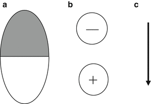
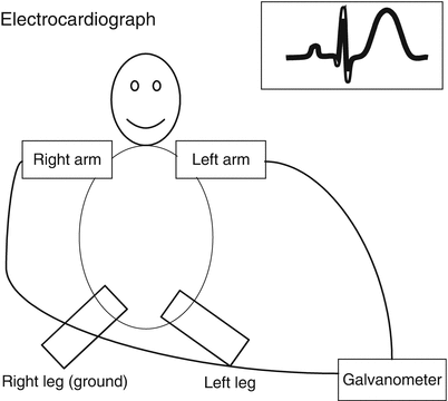
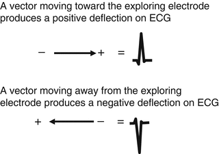

Fig. 2.1
(a) A partially depolarized myocardial fiber (gray area); (b) a dipole; and (c) a vector with a negative tail and positive head

Fig. 2.2
Electrodes attached to the right and left arms or legs are connected to a galvanometer to record the ECG, by means of a lead

Fig. 2.3
The upper vector, which is moving toward the electrode, produces a positive deflection. The lower vector moving away from the electrode produces a negative deflection
The standard leads include three bipolar limb leads and nine “unipolar” leads, three limb leads and six precordial leads. Each bipolar lead records the difference between the electrical potentials detected by two electrodes, one positive, the other negative, placed on two different points of the body surface (Fig. 2.4). If the potential difference detected by the positive electrode is greater than that detected by the negative electrode, the electrocardiograph records an upward (or positive) deflection. If the positive electrode detects a smaller potential difference is smaller than that detected by the negative electrode, a downward or negative deflection will be recorded. As for the so-called unipolar leads, the exploring (or positive) electrode records voltage at one site relative to an electrode with zero potential, which is ideally located over the center of the heart. The zero potential is achieved by joining the nonexploring electrodes to a central terminal known as the Wilson central terminal (Fig. 2.5).
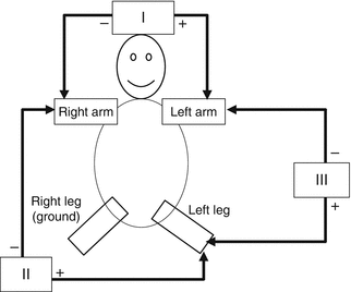
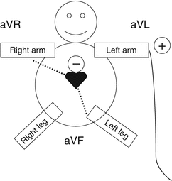

Fig. 2.4
Diagram of the bipolar limb leads. See text for details

Fig. 2.5
Diagram of the Goldberger augmented limb leads with a sample recording from lead aVL (solid line). The right arm and left leg are “short-circuited” to produce a reference electrode, which is ideally located in the center of the chest and has a potential of zero (dotted line). The aVR and aVF leads are recorded in a similar manner, short-circuiting the other leads in rotation
The Bipolar Limb Leads
The bipolar limb leads—I, II, and III—record the potential difference between two points of observation (the right arm, the left arm, and the left leg), one connected to the positive electrode, the other to the negative electrode. The left arm is conventionally considered positive relative to the right arm and negative with respect to the left leg, while the left leg is considered positive relative to the right arm. The ground electrode is conventionally placed on the right leg (Fig. 2.4). The connection of the limb leads is as follows:
Lead I: left arm (+), right arm (−)
Stay updated, free articles. Join our Telegram channel

Full access? Get Clinical Tree


