(1)
Ospedale Civile di Vigevano, Vigevano, Italy
General Considerations
The heart has the capacity to contract regularly following the delivery of an appropriate electrical stimulus (i.e., adequate in both amplitude and duration) at any point on its surface. In clinical settings, this stimulation is achieved with pacemakers (PM). These devices consist of a pulse generator and one or more leads, which are inserted into the right chamber of the heart (and sometimes the coronary sinus as well) and used to transmit the electrical impulses to the myocardium (Fig. 10.1). The generator is composed of an energy source (lithium battery) and a series of electronic circuits that characterize the PM activity. The leads are attached by screws to a connector block that links them to the generator. Together, they form a “closed” electrical circuit, the dimensions of which vary depending on whether the leads are unipolar or bipolar. In the former case, the circuit consists of an anode (the PM generator) and a cathode (located at the tip of the lead), and it is quite large. For this reason, it is susceptible to interference by external impulses. Bipolar electrodes have two poles at their tips: a proximal one that serves as the anode and a distal one that functions as the cathode. Circuits composed of bipolar electrodes are smaller and much less vulnerable to external interference.
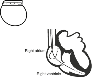

Fig. 10.1
Schematic showing the positions of the pacemaker leads in the right and left ventricles and their connection to the pulse generator
Pacemakers have two main functions (Table 10.1): pacing, which involves stimulation of the myocardium via electrical impulses generated with programmed characteristics (rate, amplitude, and duration); and sensing, that is, detection of the heart’s own spontaneous electrical activity, expressed in millivolts (amplitude of the intracardiac electrical signal). Detection of electrical activity inhibits the PM, whereas the absence of such signals for a defined period of time (PM timing) reactivates the pacing function. The pacing threshold is the lowest voltage capable of effectively stimulating the myocardial tissue; the sensing threshold is the amplitude of the intracardiac signal.
Table 10.1
Key terms related to pacemakers
(a) Pacing: emission of electrical impulses with programmed characteristics (rate, duration in milliseconds, amplitude in volts) |
(b) Sensing: detection of spontaneous electrical activity in the heart (intracardiac electric signal) |
(c) Pacing threshold: lowest voltage capable of effectively stimulating the myocardial tissue |
(d) Sensing threshold: smallest amplitude (in millivolts) of the intracardiac signal that will be detected by the PM sensors |
There are three main types of pacemakers:
1.
single-chamber PMs equipped with a single lead inserted in the right atrium or right ventricle;
2.
dual-chamber PMs with two leads, one for the right atrium, the other for the right ventricle;
3.
triple-chamber or biventricular PMs with three leads, one located in the right atrium, one in the right ventricle, and the third in a cardiac vein, which provides indirect stimulation to the left ventricle as well (Fig. 10.2).
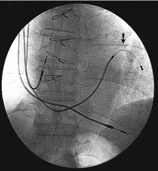

Fig. 10.2
Anteroposterior chest X-ray of the patient with an atriobiventricular pacemaker. The arrow indicates the lead placed in the coronary sinus, in the posterolateral branch. The right atrial and right ventricular leads are also visible
Normal Pacemaker Function
The PMs used today are on-demand models, whose pacing function is activated only when the sensed intrinsic heart rate falls below a certain level, which is programmed for each patient. Table 10.2 shows the other settings that are important in electrocardiographic assessments of PM function. They include the atrioventricular delay (AVD) in dual- and triple-chamber PMs (the time that elapses between spontaneous or stimulated activity in the atrium and spontaneous or stimulated activity in the ventricle); pulse amplitude and sensitivity (intracardiac signal amplitude above which the PM is inhibited). If, for example, the sensitivity is set at 2.5 mV, pacing will be suppressed as long as there are intrinsic electrical signals with amplitudes of >2.5 mV. Lower-amplitude intrinsic signals will not be sensed, and the PM will thus be induced to emit its own electrical impulses.
Table 10.2
Main programmable features of pacemakers
(a) Pulse rate (expressed in bpm) |
(b) Pulse amplitude (expressed in volts) |
(c) Pulse duration (in milliseconds) |
(d) Sensitivity (intracardiac signal amplitude—in millivolts—above which PM activity is inhibited) |
(e) Atrioventricular delay (in dual-chamber PMs, the time—in milliseconds—that elapses between spontaneous or paced atrial activity and spontaneous or paced ventricular activity) |
(f) Lead polarity (unipolar or bipolar) |
(g) Ventricular response rate (in rate-responsive PMs—see text) |
The pacing rate may be fixed (for example, 70 bpm throughout the day) or variable, a solution aimed at satisfying the changing demands of the organism. Higher rates, for example, are necessary during waking hours and during physical exercise, lower rates when the patient is sleeping. For this reason, PMs are available that “rate-responsive,” that is, capable of adjusting the pacing rate in response to changes (detected with special sensors) in muscle activity, oxygen consumption, or other biological parameters. The device can even be programmed to lower the rate during a predefined sleep period (sleep rate). In dual-chamber PMs, an upper tracking rate can also be set, which limits the rate at which the ventricles can be paced in response to intrinsic atrial activity. PM behavior when the upper pacing rate is exceeded varies, depending on the type of arrhythmia and the specific device being used.
The electrocardiographic hallmark of cardiac pacing is an electrical artifact known as a spike. It consists of a sharp vertical line, which—in the absence of malfunction—is followed immediately by an atrial or ventricular complex (depending on the site of stimulation). The paced ventricular complex is generally triggered by an impulse generated in the right ventricle, which is therefore activated earlier than the left ventricle. As a result, the QRS complex is broad with a complete LBBB pattern, and it will be positive in lead I and predominantly negative in leads II, III, and aVF (Fig. 10.3). In the presence of atrial pacing, the spike is followed by an atrial depolarization resembling a P wave of sinus origin (Fig. 10.4).
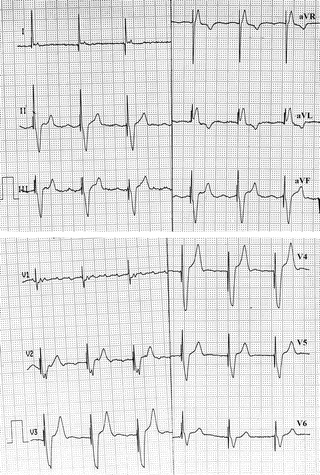
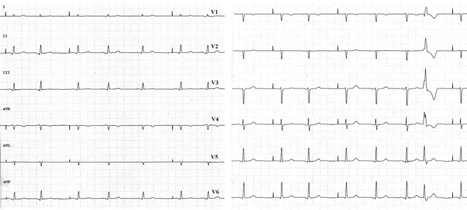

Fig. 10.3
VVI pacing associated with atrial flutter. After every pacing spike, the LBBB-type ventricular complex appears, which is produced by apical stimulation of the right ventricle

Fig. 10.4
AAI pacing. Sensed sinus activity alternating regularly with pacing spikes followed by P waves that are normally conducted to the ventricles
During ventricular pacing, the intrinsic and paced rates are sometimes similar. In this case, the ECG may contained QRS complexes that are completely PM-induced (spike + LBBB-type QRS), those that are completely spontaneous, or fusion complexes with an intermediate morphology (spike + incomplete LBBB-type QRS) (Fig. 10.5). The latter are the result of simultaneous activation of the right ventricle by the PM and by impulses generated spontaneously by the heart. Paced beats are also characterized by secondary changes involving ventricular repolarization like those seen in LBBB. Pseudofusion complexes may also be recorded: they consist of normal ventricular complexes that are preceded by a pacing spike but have the same rate as the intrinsic rhythm. In this case, depolarization of the ventricles occurs normally.


Fig. 10.5
Cardiac monitor strip: The baseline rhythm is atrial fibrillation (AF) with normal conduction to the ventricles (third and fourth complexes). The first and last two complexes are fully paced. The second complex and the third from the end are fusion complexes (with morphologic features midway between those of the spontaneous and paced beats). The fifth complex reflects pseudofusion. The QRS morphology is identical to that of the spontaneous complex: the presence of the spike preceding it is incidental and has no effects
Mention should be made of a potentially misleading phenomenon referred to as cardiac memory, which is induced by long-standing alterations in cardiac activation (e.g., those occurring during pacing). It involves repolarization changes—specifically, pseudoischemic T-wave abnormalities, mainly in the precordial leads, which appear after long periods of right ventricular pacing (Fig. 10.6) and may persist for weeks or even months after normal activation has been restored. They are related to a reversible increase in the duration of the action potential, which alters the transmural repolarization gradient. These changes have to be distinguished from those associated with acute ischemic events, which are always difficult to diagnose in patients with permanent pacemakers. They are easier to identify with if the tracing includes both paced and spontaneous complexes.
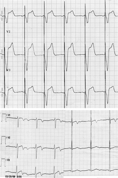

Fig. 10.6
Upper panel: Tracings recorded by leads V1, V2, and V3 during dual-chamber pacing. Lower panel: Tracings from the same leads in the absence of pacing. Obvious T-wave inversion and QT interval prolongation
The numerous characteristics and functions of pacemakers are represented by an international code composed of five letters, the first three of which are always expressed (Table 10.3). Various pacing modes can be used:
Table 10.3


International 5-letter PM code
Stay updated, free articles. Join our Telegram channel

Full access? Get Clinical Tree


