11 Techniques of Medical Thoracoscopy/Pleuroscopy
The principles and technique of medical thoracoscopy using rigid instrumentation were developed in continental Europe during the second half of the last century. They have proven their value ever since (Brandt 1964; Boutin et al. 1980, 1991; Enk and Viskum 1981; Loddenkemper 1981; Brandt et al. 1985), and have been introduced into the pulmonological community of North America by pioneers such as Aelony, Colt, Mathur, and others (Aelony et al. 1991; Colt 1992; Mathur 1994). These principles remain valid for the use of the newer generation of semirigid (semiflexible) pleuroscopes (Lee and Colt 2005; Munavvar etal.2007).
In many centers, and for most indications, medical thoracoscopy/pleuroscopy (MT/P) will be performed under local anesthesia and with conscious sedation. For the most part, the method is similar to that of tube thoracostomy with the addition of thorough inspection of the pleural space and the adjacent organs. For most indications, MT/P will start as a single-port, single-instrument rigid procedure, as first described by Jacobaeus for diagnostic purposes.
An alternative approach, as used by Jacobaeus for lysis of adhesions, is the two-entry-site technique, one entry for the examination telescope and the other for the introduction of accessory instruments, including the biopsy forceps. For this technique, neuroleptic deep sedation or general anesthesia is preferred (the technique for “Medical Thoracoscopic Sympathectomy,” see Chapter 3, p. 48 ff.).
With the introduction of the semirigid pleuroscope (LTF 160, Olympus, Japan), similar in design, accessory equipment, and handling to the flexible bronchoscope, MT/P can now be performed in a fashion analogous to flexible bronchoscopy. Thus, this technique is now increasingly used by pulmonologists who are experienced with video-controlled flexible bronchoscopy.
Endoscopy Room
MT/P can be performed either in an operating room or in a (clean) endoscopy suite (Harris et al. 1995). Cleanliness requirements are greater than for endoscopy via natural orifices, for example bronchoscopy, but less than in cardiac catheterization. Thus, the procedure is best performed in rooms used for laparoscopy or in operating rooms or in a clean bronchoscopy unit. Electrical systems should be properly isolated and protected against overload, and ideally should be attached to a voltage regulator and auxiliary electrical supply independent of the mains. Additionally, a premedication area, a washroom, and an area for cleaning and sterilizing instruments should be provided.
A properly equipped endoscopy room and arrangement of the personnel has already been shown in Figure 1.13. See also Figure 11.1. The room must contain the following:
• Thoracoscopy table: This may be a simple operating table, preferably radiolucent, or, ideally, may have a height adjustment and a back that can be raised for operating in the semisitting position. Some tables can be adjusted laterally along a longitudinal axis, which allows the patient to be repositioned easily. Although these sophisticated tables are very useful, they are certainly not essential.
• On a separate sterile table, the thoracoscope, trocar, forceps, talc atomizer, and all other accessories are placed (Fig. 11.2).
• A pneumothorax apparatus (optional).
• Adjustable aspiration equipment for the pleural fluid, with 2-L or larger collecting bottles connected to negative pressure (suction pump, electric pump, or central vacuum system with negative pressure regulator).
• Simple anesthetic equipment, with air-feed (nasal prongs) and oxygen.
• An overhead light with adjustable brightness.
• A (Mayo) stand placed sideways across the surgical table to hold the instruments.
• Electrocautery.
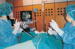
Fig. 11.1 Semirigid pleuroscopy in the endoscopy room.
• Laser equipment (optional).
• Separate mobile carts for endoscopic light sources, video equipment, and equipment for color photography.
• A viewing box or electronic medical records to display the patient’s radiographs during the procedure.
• A fluoroscope with an image intensifier and C-mount (optional).
• An alternative is ultrasonography (optional).
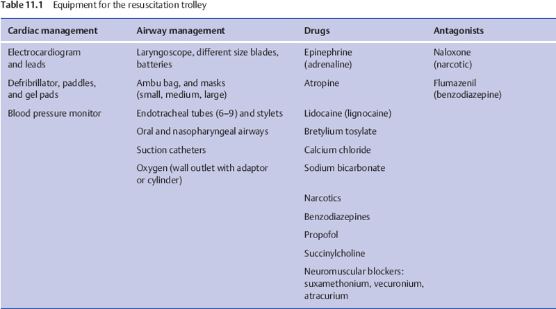
In addition, a trolley equipped with resuscitative drugs, endotracheal and chest tubes, and equipment for cardio-version and airway intubation should be easily accessible (Table 11.1).
Sterile Conditions
MT/P must be performed under strictly sterile conditions: All materials have to be sterilized, after careful cleansing, including all instruments, light conducting cables, and video cameras.
The method of disinfecting, cleaning, and sterilizing instruments and cannulas should be based on the local state and federal regulations. However, since many errors are made in handling the optics, we stress several important points:
• Predisinfecting cleaning is best accomplished before secretions have dried on the instruments by submersion in protein-dissolving, hypochlorite-containing, disinfecting and cleansing solutions. Operating channels in the instruments should be filled with this solution by means of a syringe. Cleaning should continue for at least 15 minutes.
• For the mechanical cleaning of predisinfected instruments, clean, demineralized water should be used. Preferably, instruments are rinsed with water and cleaned with soft brushes.
• The final stage of disinfection is best performed with an aldehyde-containing solution, e.g., Cidex, to which a commercially available activator is added. Large containers are needed and manipulation of the instruments with gloved hands is easier than the use of forceps. This disinfection stage should take about 15 minutes.
• Instruments should then be rinsed in a bath of fresh demineralized water. The washed and dried instruments are then sterilized by placing them, for 24 hours, into gas-tight cabinets containing formalin tablets. Following this, the optics are sterile and ready for use.
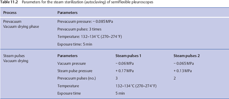
Some companies suggest autoclaving the optics in an autoclave or by means of ethylene oxide. These methods, which require high and low pressures, may damage older instruments with hairline cracks. Sterilization by means of ionizing radiation may turn the glass of normal optics brown. All video equipment is sterilized by soaking in Cidex. The semirigid (semiflexible) pleuroscope can be autoclaved (Munavvar et al. 2007) (Table 11.2).
Talc is sterilized by dry autoclaving at 160 °C, or by gamma-irradiation or by ethylene oxide gas. All have proved to be effective sterilization methods (Kennedy et al. 1995; Mattison et al. 1996).
The physician and the assistant clean their hands with the standard surgical scrub technique and then put on sterile gown/cap/mask and gloves.
The patient’s skin is prepared by shaving and disinfecting a large area, so that different points of entry are possible, reaching from the sternum up to the clavicle, across the axilla, past the scapula to the spinous processes, and down as far as the base of the thorax. Then the patient is covered with sterile sheets.
Patient Monitoring during the Procedure
The pulse, blood pressure, and respiration are carefully monitored. Depending on the equipment available, local custom, and the clinical condition, ECG and continuous pulse oximetry monitoring are used. Oxygen is administered as required (Cho et al. 2000; Loddenkemper 2000).
Personnel
Personnel required for this procedure are the physician performing the MT/P and an endoscopy assistant (or an endoscopy nurse) to assist with the instrumentation, and additionally a circulator nurse outside the sterile field to bring necessary equipment (see Fig. 1.13). Finally, depending on local custom, a nurse responsible for monitoring the patient’s oxygenation, cardiac, and ventilatory parameters as well as for titration of sedation according to patient comfort is desirable when the procedure is performed in the bronchoscopy room, or in the operating room with the support of the full anesthesia team. In an emergency, the procedure can be performed with only a physician and a nurse, but this is less efficient and may prolong the procedure.
All members of the team should be familiar with MT/P procedures and have the knowledge, competence, and resources necessary to respond to an emergent situation.
Nurses who take care of patients following MT/P should have sufficient knowledge of the procedure to provide optimal patient outcomes (Davidson and Colt 1997).
Equipment
Since the first detailed description by Jacobaeus in 1910; rigid endoscopic instruments such as stainless-steel trocars and telescopes have been pivotal in the performance of thoracoscopy (Fig.11.2) and VATS. With the introduction of the semirigid (semiflexible) pleuroscope, similar in design and handling to the flexible bronchoscope, pleuroscopy is now frequently performed with this technique, analogous to flexible bronchoscopy. An additional advantage of the pleuroscope is that parts of the bronchoscopy equipment (e.g., the light source) can be used, reducing the acquisition cost.
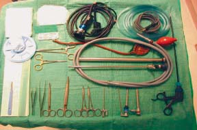
Fig. 11.2 Instruments for rigid thoracoscopy (Storz company).
The equipment requirements include trocar, thoracoscope/pleuroscope, biopsy forceps, unipolar coagulation forceps, light sources, video system, aspiration system, talc, chest tubes, and pleurovacs. The usual diameter of the rigid thoracoscope is 7-9 mm, that of the semirigid pleuroscope 7 mm.
Corresponding to the historical development, we will describe first the rigid technique, followed by the flex-rigid technique.
Rigid Thoracoscopes
One type of rigid thoracoscope is manufactured by the German company Storz (in the United States available from Karl Storz Endoscopy America Inc, Culver City, CA). The diameter of the trocar most commonly used is 10 mm and of that the thoracoscope 9 mm (7-12 mm thoracoscopes are also available) with a working channel of 3 or 5 mm. The trocar consists of an obturator and cannula with a blunt conical tip, adjacent to which there is a small hole connected to the trocar lumen, open to the exterior, so that penetration into the pleural cavity is signaled. Unlike the instruments for laparoscopy, this trocar does not have to be airtight. Air should be allowed to enter and leave the thoracic cavity freely. Examination will be limited by pain if the trocar is larger than 10 mm. Trocars are also available with diameters of 5 and 3.75 mm for performing thoracoscopy in children. In infants, optics and instruments similar to those used in infant rigid bronchoscopy are used.
Figure 11.3 shows a selection of thoracoscopy instruments. Besides the biopsy forceps, needle biopsy, and suction catheter, the working channel also accommodates electrocautery. Thoracoscopes are available with various angles of vision including 0°, 45° or 90°. Direct viewing is more natural when moving the thoracoscope in a circular manner: most of the thoracic cavity can be viewed. With an oblique thoracoscope, one can also obtain a panoramic view of the whole chest cavity as well as of areas difficult to view. The 3- or 5-mm insulated coagulation forceps can be introduced through the working channel for biopsies. A bayonet optical system with an instrumentation channel and the appropriate instruments may facilitate directed fluid suction, electrocautery or directed insufflation of talc.
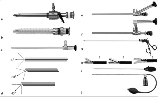
Fig. 11.3 Selection of instruments for rigid medical thoracoscopy. (Reprinted with kind permission from Karl Storz GmbH & Co. KG, Tuttlingen, Germany.)
a Trocar with multifunctional valve with insufflation stopcock, 11 mm, autoclavable.
b Trocar with silicone leaflet valve, 11 mm, autoclavable.
c Telescope, particularly suited for single-incision thoracoscopy, here with light shaft for photography, diameter 10 mm, length 31 cm, trocar size 11 mm.
d Various fields of view. (1) Straight-forward telescope 0°, diameter 10 mm, length 31 cm, autoclavable. (2) Forward-oblique telescope 30°, diameter 10mm, length 31 cm, autoclavable. (3) Telescope 45°, diameter 10 mm, length 31 cm, autoclavable.
e Straight-forward telescope 0° with angled eyepiece, diameter 10 mm, working length 27 cm, with instrument channel 6 mm, trocar size 11 mm, single puncture.
f Straight-forward telescope 0°, with parallel eyepiece (bayonet optic), diameter 10 mm, working length 27 cm, with instrument channel 6 mm, trocar size 11 mm, single puncture.
g Dissecting and biopsy forceps, rotational, that can be dismantled, with connector pin for unipolar coagulation, 5 mm.
h Single-action jaws: (1) dissecting and biopsy forceps; (2) biopsy forceps; (3) scissors.
i Dissecting electrodes, with connector pin for unipolar coagulation, L-shaped, size 5 mm, working length 43 cm.
j Powder blower, with rubber bulb, size 5 mm, working length 42 cm.
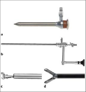
Fig. 11.4 Selection of instruments for rigid medical thoracoscopy. (Reprinted with kind permission from Richard Wolf GmbH, Knittlingen, Germany.) a Trocar sleeve with lateral tap, metal, straight distal tip. b Straight-forward telescope with parallel eyepiece (bayonet optic). c Biopsy forceps with double-spoon jaws. d Grasping biopsy forceps.
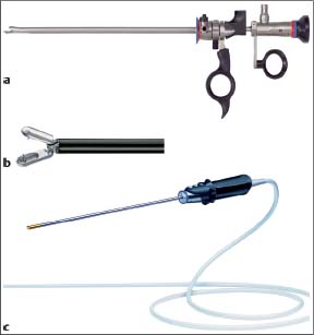
Fig. 11.5 Selection of instruments for rigid medical thoracoscopy. (Reprinted with kind permission from Olympus Medical Systems Europa GmbH, Hamburg, Germany.) a Rigid optical biopsy forceps with 4-mm diameter OES Pro Telescope. b Biopsy forceps. c 5-mm scope with distal video chip (endo eye).
A xenon light source satisfies the requirements for high-quality visual exploration and video documentation.
The instruments of the German company Richard Wolf GmbH are very similar (Fig. 11.4). They are most commonly used with the two-entry-site technique. Since instruments used for laparoscopy are practically identical, laparoscopic equipment as produced, for example, by Olympus Corporation, can also be used for one-entry rigid medical thoracoscopy (Fig. 11.5).
Rigid minithoracoscopes (Tassi and Marchetti 2003) (or arthrocopes as used by Ash and Manfredi 1974) are much less suited for thoracoscopy since they have the disadvantage that a second point of entry is necessary for biopsy purposes and insertion of a large drainage catheter through the same channel post thoracoscopy is impossible (Janssen et al. 2003; Rodriguez-Panadero et al. 2006).
The Semirigid (Semiflexible) Pleuroscope
A semirigid (semiflexible, flex-rigid) pleuroscope must satisfy two requirements:
1. To provide high-quality visual exploration and video documentation.
2. To allow multiple, large pleural biopsies of sufficient size to ensure a definitive histopathological diagnosis, while accommodating electrocautery when necessary.
The equipment used has been developed by the Japanese company Olympus in conjunction with pulmonologists for a single-puncture technique (Ernst et al. 2002; Lee and Colt 2005; Wang et al. 2008). These instruments comprise several parts, as discussed below.
Pleuroscope
The semirigid pleuroscope (Pleuravideoscope model LTF-160 or -240 (Olympus, Japan) consists of a handle that is similar to the standard flexible bronchoscope, and a shaft that measures 7 mm in outer diameter and 27 cm in length (Fig. 11.6). The shaft is made up of two sections: a 22-cm proximal rigid portion and a 5-cm flexible distal end. The flexible tip is movable by a lever on the handle, which allows two-way angulation capability of 160° up and 130° down. It also has a 2.8-mm working channel that accommodates biopsy forceps, needles, and other accessories, and is compatible with various electrosurgical and laser procedures. The instrument is used with a single-port technique. A single 1-cm skin incision that accommodates a disposable 8-mm inner diameter flexible trocar suffices (Fig. 11.7).
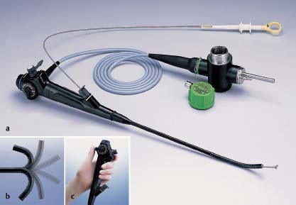
Fig. 11.6a The semirigid (semi-flexible) pleuroscope (Olympus Corporation). Control section allows handling as with the flexible bronchoscope. b Angulation capability 160° upward/130° downward, c Diameter of the pleuroscope 7-mm, with a 2.8-mm diameter of the working channel. (Reprinted with kind permission from Olympus Corporation.)
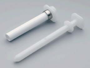
Fig. 11.7 Rigid trocar and cannula with valve for the semiflexible pleuroscope (Olympus). Outer diameter 10 mm, inner diameter 8 mm.
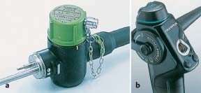
Fig. 11.8a A dedicated, green waterproof cap protects the electrical connections of the LTF 160 pleuroscope during autoclaving. b Waterproof control section. (Reprinted with kind permission from Olympus Corporation.)
Moreover, the LTF 160 model allows autoclaving, thereby obviating important questions and issues related to asepsis (Fig. 11.8a, b). The other notable advantage of the semirigid pleuroscope over rigid instruments is that it interfaces easily with existing processors (CV-160, CLV-U40,) and light sources (CV-240, EVIS-100 or 140, EVIS EXERA-145 or 160) made by the manufacturer for flexible bronchoscopy or gastrointestinal (GI) endoscopy, which are available in most endoscopy units without additional cost (Fig. 11.9).
The optical quality allows excellent visual exploration as well as good video recording or photographic documentation. The flexible tip will allow various angles of vision, including straight-ahead and oblique angles of view. The lateral or oblique angles of view are essential to endoscopic examination. As with a bronchoscope, one very quickly becomes accustomed to movement of the tip simply by rotating the pleuroscope and manipulating the tip so that a superb panoramic view of the entire pleural cavity can be achieved.
Forceps
The 3-mm forceps for biopsy under direct vision, using a single point of entry, is ideal for sampling the parietal pleura. The coagulation forceps is especially well suited for biopsy of the diaphragmatic pleura and thick, hard, or fibrous pleural lesions, including asbestosis pleural plaques (Fig. 11.10a, b). Other accessories for electrosurgical and laser procedures are shown in Figure 11.11 a-c.
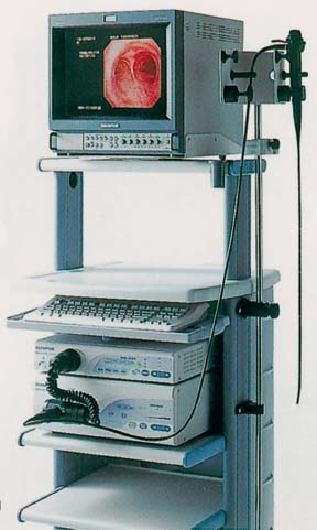
Fig. 11.9 Light source, processor, and monitor used with the bronchovideoscope. (Reprinted with kind permission from Olympus Corporation.)
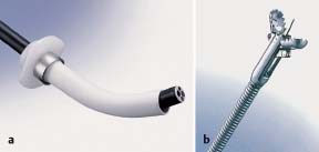
Fig. 11.10a Pleuroscope with the flexible forceps, introduced through the trocar shaft. b Swing jaw needle forceps (alligator jaw type). (Reprinted with kind permission from Olympus Corporation.)
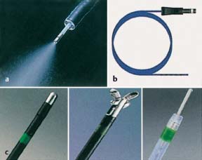
Fig. 11.11 Additional accessories for electrosurgical and laser procedures that can be introduced through the semirigid (semiflexible) pleuroscope. a Spray catheter. b Argon plasma coagulation catheter (Erbe). c (Left to right) coagulation electrode, hot biopsy forceps, electrosurgical knife. (a and c reprinted with kind permission from Olympus Corporation.)
Auxiliary Instruments and Accessories for Medical Thoracoscopy/Pleuroscopy
• Sterile sheets (e.g., Laparotomy Pack IV, Johnson & Johnson Medical Inc. Arlington TX, USA).
• Sterile gowns and gloves for the physician and assistant.
• Needles, syringes, local anesthetics, scalpels, 4×4, suture.
• Various forceps, needle holders, clamps, hemostats (usually all available in a chest tube insertion tray).
• Electrocautery/laser.
• Talc can or talc atomizer.
• Chest tubes between 24 F and 32 F (self-contained chest tube set with inner stylet).
• Underwater drainage systems.
• Anti-fog solution.
• Light sources, light cables.
• Video camera, video tapes, photo camera (optional).
• Manometer to measure pleural pressure (optional).
• Laser equipment (optional).
• Equipment for autofluorescence thoracoscopy or narrow-band imaging (optional).
• Pneumothorax apparatus and pneumothorax needles (optional).
Pneumothorax instruments that operate according to the principle of communicating tubes and utilize a water manometer are the simplest and least prone to malfunction. Electronic instruments, such as for filling the peritoneum, are unsuitable since they do not allow immediate switching from filling to suction. (See Fig. 11.12 for a diagram of the historical pneumothorax apparatus.)
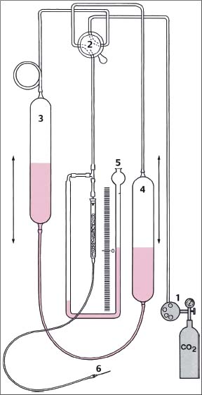
Fig. 11.12 Schematic diagram of the pneumothorax apparatus according to the principle of communicating tubes in the position “fill.” (1) CO2 lung automat; (2) stopcock in position “fill”; (3) upper reservoir bottle from which water is draining; (4) lower reservoir bottle into which the water drains and thus pushes the fill gas through the pneumothorax needle into the fill gas tube; (5) water manometer which in the position “fill” indicates the back pressure before the pneumothorax needle into the fill gas tube; (6) cannula with pneumothorax needle. (From Brandt et al. 1985.)
The fluid reservoirs are graduated and filled with sterile water. By raising and lowering the bottles and appropriately setting the multidirectional stopcock, the filling gas can be directed from a gas reservoir or so-called Lung Automat (Dräger) directly from the compressed gas cylinder (if carbon dioxide is used as filling gas, this may minimize the effects of possible air embolism due to its more rapid absorption). By repeatedly changing the position of the bottles, the system can be flushed with the filling gas. In the stopcock position “fill,” the water runs from the upper bottle into the lower one and as a result, pushes the filling gas into the nozzle and via the connecting tubing to the pneumothorax needle. While the gas is flowing, the attached water manometer shows the pressure in the tubing and needle. In the stopcock position “measure,” the intrathoracic (intrapleural) pressure can be recorded. If the scales are graduated in centimeters, then positive or negative pressure can be read directly from the water manometer (the centimeter scale must be multiplied by 2 since it is the pressure difference between the two columns that is important). By switching the stopcock to the position “suction,” negative pressure can be rapidly produced to provide suction.
Phases of Medical Thoracoscopy/Pleuroscopy
• Preparation of the patient (information, fasting status, shaving of the skin).
• Premedication (optional).
• Radiographic review is mandatory in each patient.
• Positioning of the patient.
• IV line, nasal oxygen, ECG electrodes, blood pressure meter, oximeter.
• Choice of entry site on the basis of radiography/CT or ultrasound/fluoroscopy “on the table.”
• Careful aspiration of fluids in case of pleural effusion.
• Insufflation (or spontaneous entrance)of air if necessary.
• Induction of pneumothorax if indicated.
• Careful local anesthesia plus sedation as needed.
• Introduction of the trocar.
• Inspection of the thoracic cavity using thoracoscope/ pleuroscope.
• Documentation by photography or video.
• Insufflation of additional air/CO2 into the pleural cavity if necessary.
• Section of adhesions preventing inspection if necessary.
• Obtaining multiple biopsy samples.
• Control of bleeding.
• Talc pleurodesis if necessary after additional analgesics.
• Systematic suction drainage.
• Surveillance during recovery.
Patient Positioning
The patient lies usually on the healthy side in a lateral decubitus position with the involved side up; the head is resting on a pillow (Fig. 11.13). The patient’s movement is minimized with cushioned support; the arm is raised over the head with the help of a sling. A rolled-up sheet or a pillow is placed on the table under the patient’s flank, causing the spine to flex laterally, thus widening the intercostal spaces at the procedural site. This axillary roll also protects the brachial plexus provided it is not placed too high in the axilla.
The final position of the patient, e.g., in the case of localized lesions, will be determined by the chosen point of entry depending on the location of the lesion as shown by chest radiography/CT or ultrasound (see “Selecting the Point of Entry” below). Figure 11.14 shows, by means of a CT image, how the force of gravity can be used to encourage the lung to fall out of the field of view. The most often used lateral position (Fig. 11.14a) provides the best view in cases of pleural effusion and diffuse lung disease. The prone position (Fig. 11.14b) is best for inspecting the posterior abnormalities. The supine position (Fig. 11.14c) is optimal for visualizing abnormalities of the lung, chest wall, and mediastinum located anteriorly.
A special situation is given for bilateral sympathectomy where the patient is placed in the supine position (see “Medical Thoracoscopic Sympathectomy,” Chapter 3, p. 48 ff.).
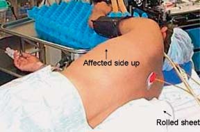
Fig. 11.13 Patient lying in the lateral decubitus position with the healthy side up; the head rests on a pillow; the arm is raised over the head with the help of a sling; a rolled-up sheet is placed on the table under the patient’s flank; the axillary roll protects the brachial plexus.
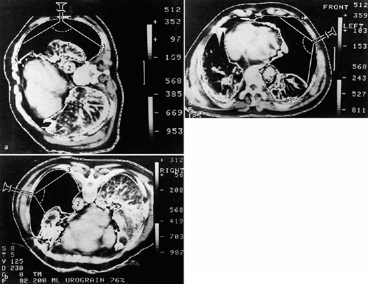
Fig. 11.14 Computed tomography images with two-window technique at the level of the ninth thoracic vertebra in a patient with a complete, left-sided pneumothorax for the purpose of demonstrating the influence of position on the thoracoscopic visualization of various structures (CT: H. Witt, Berlin). (From Brandt et al. 1985.)
a Lateral position: If entered laterally, visualization of the lung surface (1) is optimum, of the anterior mediastinum (4) is partial, of the posterior mediastinum (2) is not possible, and of the paravertebral space (3) is fairly good.
b Prone position: The lung (1) has retracted and fallen forward. The dorsum of the posterior lung and mediastinum with aorta (2) and paravertebral space (3) are easily accessible via the lateral approach.
c Supine position: The lung falls toward the back. Complete visualization of the anterior mediastinum (4) and of the anterior portions of the lung (1) with lateral approach. The posterior mediastinum (2), and the paravertebral space (3) cannot be visualized.
Selecting the Point of Entry
An axillary point of entry is selected as standard in most cases. The axillary triangle has no large muscle obstructing passage of the instruments: it is bordered anteriorly by the lower edge of the pectoralis major muscle, posteriorly by the anterior edge of the latissimus dorsi muscle, and inferiorly at the level of the diaphragmatic insertions. Its apex reaches the second intercostal space.
Thoracic and specifically intercostal anatomy is depicted on many of the figures included in the Atlas part. The skin overlies subcutaneous adipose tissue, which is superficial to the fascial lining of the intercostal muscles. Three layers of intercostal muscles lie over and between the ribs. Lining the inside of the thoracic cavity is the parietal pleura. The intercostal neurovascular bundle traverses the chest wall from the vertebral body around the circumference of the chest and again to the midline anteriorly in a depression on the inferior aspect of each rib, the intercostal groove. Obviously, in certain areas other muscle groups may be present between the skin and thoracic cage, such as the pectoralis group anteriorly and the latissimus dorsi posteriorly; thus the axillary triangle has no large muscles obstructing the passage of the instruments.
The point of entry is generally near the mid-axillary line, within this triangle. The final location of this insertion port will be determined by the indication: for pleural effusions most commonly in the fifth, sixth, or seventh intercostal space. The last two spaces are especially preferred when metastatic tumor and diffuse malignant mesothelioma are suspected to reach the most common sites of these malignancies. This provides an excellent view of both the diaphragm and the costovertebral gutter where malignant lesions (if present) will usually be reachable.
In case of spontaneous pneumothorax, the entry port will be located at the third or fourth intercostal space, to allow a thorough inspection of the lung apex and because a leak, if present, is usually in the upper lobe (see “The Place of Medical Thoracoscopy/Pleuroscopy in the Management of Pneumothorax,” Chapter 3, p. 41 ff.).
Point of Entry for Specific Localized Lesions
An axillary point of entry is selected in most cases. In the few exceptions, the site of entry depends on the anticipated location of the pathological lesion. To provide a good view of the lesion, the patient has to be placed in such a position that the lung falls out of the field of view (Fig. 11.14a-c).
The entry in the mid-axillary line at the level of the fourth or fifth intercostal space, in the lateral position, allows best the complete thoracic cavity inspection. Metastatic tumors or diffuse malignant mesothelioma are commonly found in the inferior costovertebral angles and on the diaphragmatic surfaces. Therefore, entry in the fifth or sixth or seventh intercostal space allows direct visualization of these lesions.
In unusual cases, other points of entry are used depending on the clinical setting and/or the chest radiography/CT or ultrasound results. For instance, the second or third anterior intercostal spaces are chosen in cases of pneumothorax when anterior and superior blebs are suspected; one must bear in mind that a pleural lesion that is too close to the point of entry cannot be viewed.
The lesion is approached most easily from the opposite side. Therefore, one should choose:
• For posterior lesions: the anterior axillary line.
• For anterior lesions: the posterior axillary line.
• For lateral lesions: the mid-clavicular line.
Every effort must be made to identify the precise level of the lesion on the radiograph/CT image so that the appropriate intercostal space can be used for the point of entry.
Techniques for Introduction of the Endoscope in Pleural Effusion, Pneumothorax, and Other Conditions
The single-puncture technique is the easiest method to learn and is commonly used by pulmonologists. A double-puncture method will increase the diagnostic and therapeutic benefit of the procedure in selected cases. With the double-puncture method, the second site of entry is selected closer to the area of interest. This will permit the viewing of areas difficult to reach, such as the mediastinal pleural surfaces and the apex of the lung. This may also be facilitated by the use of the semirigid pleuroscope with its flexible tip.
However, one (or two) additional points of entry can be made under direct thoracoscopic guidance as needed. This may be the case when extensive adhesions are present (Fig. 11.15), when the single entry site does not allow for complete inspection or does not allow one to reach a suspect lesion for biopsy, when more elaborate procedures are indicated (e.g., extensive adhesiolysis, visceral pleural/lung biopsies, sympathicolysis,…..), or when it is necessary to control hemorrhage after biopsy. When medical thoracoscopy is performed under general anesthesia, the two-port technique is most often used. The accessory instrumentation usually is passed through a 5- or 7-mm insulated trocar. The principles of biopsy of the parietal pleura are the same as described above. Usually, a 5-mm double-spoon insulated coagulation forceps is used (see “Biopsy Techniques”, p. 89 ff.).
Access to the Pleural Space
Since it is impossible to perform the procedure if the pleural space is completely obliterated, the lack of a sufficiently large pleural space is an absolute contraindication. Thus, the most important prerequisite for medical thoracoscopy/pleuroscopy is a freely accessible pleural space that allows introduction of the trocar and thoracoscope/pleuroscope without injury to the lung or other organs (it should be recalled that the diaphragm lies in a much higher position in the supine patient than in the upright patient).
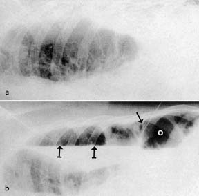
Fig. 11.15 Radiological monitoring before and after induction of pneumothorax in pleural effusion with adhesions. a Fluoroscopy in the lateral decubitus position before induction. b After induction of pneumothorax, puncture needle (→) within the adhesions, air-fluid level ( ). Point of insertion (o) of the trocar away from the adhesions. (From Brandt etal. 1985.)
We list here some important points to be considered before the insertion of the thoracoscope/pleuroscope as well as several possibilities for providing a safe entry to the pleural space:
• A pleural symphysis can be suspected from the patient’s history (previous pleurisy or thoracic surgery) or/and from imaging (radiography, CT, MRI, ultrasound, and/or fluoroscopy).
• A partial pneumothorax of at least 100-200 mL should be present or induced to permit the introduction of instruments without risk.
• The simplest access is available in case of a preexisting complete pneumothorax.
• If the preexisting pneumothorax is only partial, due to adhesions, these should be localized by the imaging techniques to avoid the introduction of the trocar in the area of the adhesions.
• In the presence of a large pleural effusion, the trocar can also be introduced directly without producing a pneumothorax (if fluid is readily aspirated as the pleural space is entered), although this may carry a somewhat greater risk of injury in case of unsuspected adhesions.
• In the presence of a smaller pleural effusion, a needle puncture should be performed at the level of greatest opacification/dullness or, ideally, under sonographic (Macha et al. 1993; Hersh et al. 2003; Noppen 2003b) or fluoroscopic guidance (Brandt et al. 1985; Loddenkemper 1998). When pleural fluid is aspirated, the syringe is removed from the needle and air will enter into the pleural space either spontaneously or when asking the patient to take a few deep breaths. The entry of air causes the lung to collapse away from the chest wall, and creates a pleural space for safe trocar insertion.
• Alternatively, if one is certain that the needle is well positioned in the pleural fluid (and not, for example, in the lung), air can be introduced into the pleural space by means of a syringe. Most often a few milliliters of air are sufficient to provide good ablation of the lung from the chest wall pleura.
• Some authors recommend aspirating 200-300 mL of fluid from the pleural cavity using a needle, angiocatheter, arrow thoracentesis catheter, or reusable Boutin pleural puncture needle (2 mm × 80 mm reusable trocar with side tap) and injecting an equivalent amount of ambient air (Lee and Colt 2005).
• Some experienced teams regularly perform MT/P in pleural effusions without any form of image-guided induction of a pneumothorax. In one series of more than 700 MT/P procedures conducted without preprocedural imaging of the entry site, induction of a pneumothorax was impossible in only 10 patients, due to extensive adhesions. No major complications such as bleeding were observed (Noppen 2003 b). Furthermore, in these cases biopsies could be performed using the extended thoracoscopy technique (Janssen and Boutin 1992) (see below).
• Greater safety is provided under ultrasound guidance, which allows the operator to localize the pleural effusion and to avoid transecting significant adhesions, with possible complications such as bleeding and injury to the lung, diaphragm, and other thoracic structures (Macha et al. 1993; Hersh et al. 2003; Noppen 2003 b).
• An alternative approach is fluoroscopy “on the table” after introducing air into the pleural cavity, which will show the air-fluid level as well as adhesions if present (Fig. 11.15). This is done with the patient in the lateral decubitus position and the hemithorax to be studied facing upward (Fig. 11.16) (Brandt et al. 1985; Mathur et al. 1994; Loddenkemper 1998).
• If it is difficult to aspirate pleural fluid, the pneumothorax can be induced with special pneumothorax needles (of different types, all with a blunt tip and a side hole as in the Deneke and Veress needles [Fig. 11.17], or the Saugmann or Boutin needles), under pressure control, ideally with a manometer or a pneumothorax apparatus (see Fig. 11.12).
• In case of difficulties in creating a pneumothorax because of adhesions, the blunt dissection technique is recommended, as first described by Janssen and Boutin in 1992 as “extended thoracoscopy: a biopsy method to be used in case of pleural adhesions” (Janssen and Boutin 1992). This usually involves gentle dissection of the pleural adhesions with a finger to verify the existence of a free pleural space before advancing the instruments into the pleural space (Mares and Mathur 1997): The skin, subcutaneous tissues, intercostal muscles, periosteum of the ribs, and pleura are anesthetized as for the other techniques. The skin is incised superficial to the ribs below the desired interspace. A (Kelly) forceps is used for blunt dissection through the subcutaneous tissues, intercostal muscles, and pleura. Once the pleura is penetrated by the forceps, a finger is placed through the site and the nearby thoracic structures are palpated (Fig. 11.18). Palpation is performed to ensure that there are no pleural adhesions that would misdirect the trocar tube toward the lung and possibly cause the tube to penetrate the visceral pleura and enter the lung parenchyma. If fibrinous adhesions are found, they may be gently broken down with the probing finger. This ability to manually palpate the pleura and break down adhesions constitutes one of the advantages of this particular technique. Disadvantages include the greater trauma to skin and intercostal muscles, with greater risk of bleeding. However, local control of bleeding can be more easily accomplished.
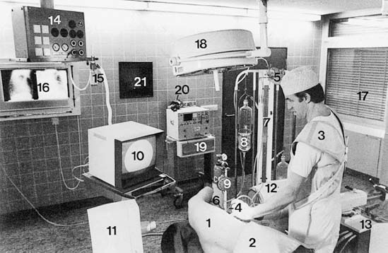
Fig. 11.16 Set-up for induction of pneumothorax. (1) Patient in the lateral decubitus position with lead apron (2) on his abdomen. (3) Physician (the author) with lead apron. The left hand guides the pneumothorax needle (4), the right hand the stopcock (5) of the pneumothorax apparatus. In the field of view of the physician are: the patient’s face (6), water manometer (7), meniscus of the graduated filling flask (8), lungautomat with CO2 cylinder (9), monitor (10) of the radiographic image intensifier. (11) X-ray tube and (12) picture tube on the C arm which runs under the table. The radiography equipment (13) is controlled with a footswitch. (14) Central service unit with oxygen, compressed air and oxygen humidifier (15). (16) Radiograph view box with PA and lateral chest radiographs. (17) Window blind (17); (18) surgical light; (19) resuscitation unit with ECG monitor and defibrillator; (20) bag ventilator; (21) lead glass window for observation. (From Brandt et al. 1985.)
Stay updated, free articles. Join our Telegram channel

Full access? Get Clinical Tree


