Surgical Anatomy of the Heart: Correlation with Echocardiographic-Imaging Planes
Bruce Bollen
Carlos Duran
Robert M. Savage
A familiarity with cardiovascular anatomy is fundamental to understanding the standard imaging planes commonly utilized in daily clinical applications of ultrasound in the perioperative environment. This is especially true for intraoperative transesophageal and epicardial echocardiography where anatomic localization of pathology is required to answer specific surgical questions. In addition, pathologic processes, such as endocarditis, dilatation of cardiac chambers and vascular structures, and congenital abnormalities may result in distortion of normal relational anatomy making it challenging even for experienced echocardiographers to recognize the structural anatomy of the heart. Understanding the three-dimensional anatomic relation of the cardiac fibrous skeleton, cardiac chambers, valves, and vascular structures provides a greater ability to recognize resulting distortions of normal anatomy. It will be the purpose of this discussion to introduce the novice echocardiographer to basic cardiac anatomy, yet challenge the experienced echocardiographer to develop a greater understanding of cardiac anatomy in relation to their practice.
FIBROUS SKELETON OF THE HEART
The fibrous skeleton of the heart is formed by the U-shaped cords of the aortic annulus and their extensions forming the right trigone, left trigone, and a smaller fibrous structure from the right aortic coronary cusp to the root of the pulmonary artery (1). This “skeleton” plays a primary function of supporting the heart within the pericardium. A continuum of fibrous tissue extends from the fibrous skeleton providing attachments for the atriums, ventricles, and valve leaflets (Fig. 5.1).
Three U-shaped cords of the aortic annulus join to each other at the commissures of the aortic valve, forming a scalloped fibrous crown-like skeleton of the aortic valve. The right fibrous trigone extends from the base of the noncoronary cusp, and is more substantial than the left fibrous trigone. The left fibrous trigone extends from the base of the left coronary cusp. A scalloped area is formed between the right and left trigones and the annular attachment of the left and noncoronary cusp. This is called the intertrigonal space and has no proper skeletal structure. A broad membranous curtain extending from the aortic annulus to the mitral annulus covers this space.
This broad membrane is often referred to as the aortic curtain and the space as the mitral aortic interstitial fibrosis or intervascular space. This membrane merges with the anterior third of the mitral annulus becoming the middle portion of the anterior leaflet of the mitral valve.
This broad membrane is often referred to as the aortic curtain and the space as the mitral aortic interstitial fibrosis or intervascular space. This membrane merges with the anterior third of the mitral annulus becoming the middle portion of the anterior leaflet of the mitral valve.
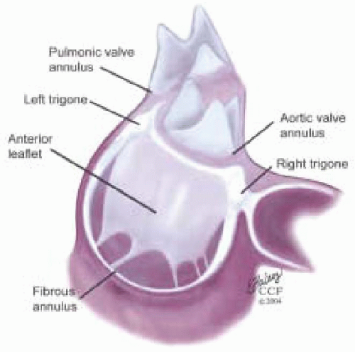 FIGURE 5.1. Fibrous skeleton of the heart consisting of three U-shaped cords of the aortic annulus, the right and left trigones, and the fibrous structure from right coronary cusp to the root of the pulmonary artery. Extensions from skeleton include the aortic curtain, mitral and tricuspid annulus, and anterior leaflet of the mitral and pulmonic valves. |
From the left and right fibrous trigones a fibrous tissue continuum extends around the left and right atrioventricular orifices, forming the annuli fibrosi of the mitral and tricuspid annuli. The mitral annulus is the transition area where the left atrium, mitral valve leaflets, and left ventricle come together. The mitral valve leaflets form a membranous curtain attaching to the mitral annulus. The anterior circumferential portion of the mitral annulus associated with the left trigone, intertrigonal space, and right trigone area is the attachment point of the anterior leaflet of the mitral valve. This anterior portion of the mitral annulus has minimal shape change during the cardiac cycle and is less prone to dilation because of its rigid structure. Its margins are defined surgically by two dimples raised at the border of the right and left trigones when lifting the anterior leaflet.
The annuli fibrosi of the mitral annulus becomes thinner and poorly defined as it extends posteriorly from the left and right trigones. This portion of the annulus is poorly supported and is prone to dilation in pathologic states. The posterior leaflet of the mitral valve attaches to this portion of the annulus. Dilation of the annular attachment of the posterior leaflet creates increased tension on the middle scallop of the posterior leaflet, explaining the 60% occurrence of chordal tears in the middle scallop of the posterior leaflet (2).
From the base of the annular cord of the noncoronary cusp a membrane extends becoming continuous with the interventricular septum. Its downward extension forms the membranous septum. This relationship is important in understanding the anatomy of the left ventricular outflow tract (LVOT).
CARDIAC VENTRICLES
The right ventricle has two openings—the tricuspid and pulmonic valves—separated by a band of mycocardium, the crista supraventricularis. The left ventricle (LV) has a common opening at its base shared by the aortic root and the mitral valve (Fig. 5.2). Although sharing a common opening in the left ventricle, the aortic and mitral valves are set at an angle to each other (Fig. 5.3). The changing of this angle during valve repair has been reported to influence the likelihood of postrepair systolic anterior motion (SAM) of the mitral valve (2).
The left ventricular outflow tract (LVOT) is defined anteriorly by the membranous and the muscular portions of the interventricular septum (3,4). The superior part of the membranous septum is directly continuous with the right wall of the aortic root. The membranous septum is beneath the noncoronary cusp. The posterior portion of the LVOT is defined by the anterior leaflet of the mitral valve.
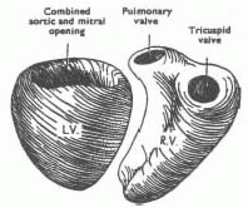 FIGURE 5.2. Diagram showing that the tricuspid and pulmonary valves occupy separate openings within the right ventricle, whereas the mitral and aortic valves share a common opening in the base of the left ventricle. |
To facilitate reporting of left ventricular function the ventricle is divided into segments. Various segmental classifications have been utilized. The Society of Cardiovascular Anesthesiologists and the American Society of Echocardiography have developed a 16-segment model of the LV based on the recommendations of the Subcommittee on Quantification of the ASE Standards Committee. This model divides the LV into three levels: basal, mid, and apical. The basal and mid levels are each divided circumferentially into six segments and the apical into four (Figs. 5.4 and 5.5) (5).
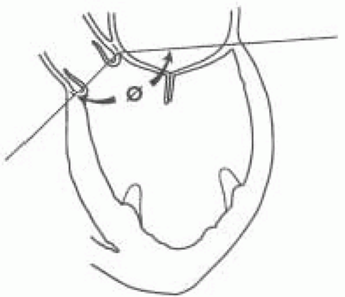 FIGURE 5.3. Diagram of the mitroaortic angle (Ø). |
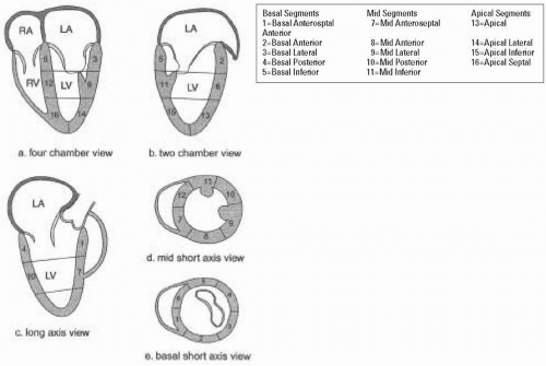 FIGURE 5.4. Sixteen-segment model of the left ventricle. A: Four-chamber views show the three septal and three lateral segments. B: Two-chamber views show the three anterior and three inferior segments. C: Long-axis views show the two anteroseptal and two posterior segments. D: Mid short-axis views show all six segments at the mid level. E: Basal short-axis views show all six segments at the basal level. |
TRICUSPID VALVE
The tricuspid valve of the right ventricle has three leaflets. Its orifice viewed from the right ventricle is triangular with anterior, posterior, and septal sides. The tricuspid annulus is relatively indistinct especially in the septal region. The tricuspid valve has three leaflets: anterior, posterior, and septal. The anterior leaflet, the largest of the three, is semicircular to quadrangular in shape. Chordae attaching to the anterior leaflet arise from the anterior and medial papillary muscles. The posterior leaflet is usually the smallest. The leaflet has several indentations or clefts that give it a scalloped appearance. Its chordae arise from the posterior and anterior papillary muscles. The septal leaflet is primarily attached to the septum, the remainder attaching to the posterior wall of the right ventricle (Fig. 5.6). Part of its basal attachment is to the posterior wall of the right ventricle but most of its attachment is to the septal wall. Its chordae arise from the posterior and septal papillary muscles.
Silver et al. defined three commissures: anteroseptal commissure, anteroposterior commissure, and posteroseptal commissures (8). These commissures define the margins of the leaflets of the tricuspid valve. The anteroseptal commissure is defined by a deep indentation in the membranous interventricular septum where the anterior and septal walls of the right ventricle join. The anteroposterior commissure is defined by fan-shaped chorda at the acute margin of the right ventricle and the anterior papillary muscle pointing to the commissure. The posteroseptal commissure is defined by attaching fan-shaped chordae, the most medially placed posterior papillary muscle, and a fold of tissue on the septal leaflet.
The basal attachments of the leaflets to the annulus are at different levels in the heart. The posterior leaflet and the posteroseptal half of the septal leaflet are roughly horizontal and about 15 mm lower than the highest part of the valve’s attachment, which occurs at the anteroseptal commissure near the midpoint of the membranous interventricular septum.
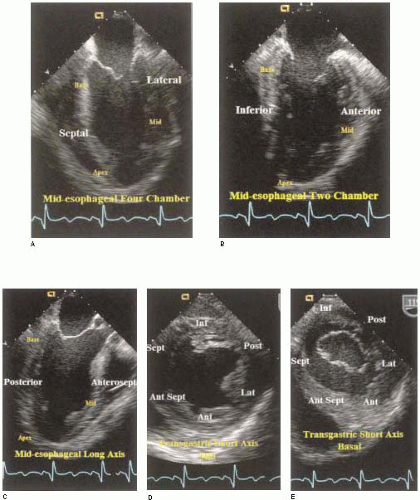 FIGURE 5.5. Sixteen-segment model of the left ventricle. A: Midesophageal four chamber imaging plane showing the three septal and three lateral segments. B: Midesophageal two-chamber showing the three anterior and three inferior segments. C: Midesophageal long axis views showing the two anteroseptal and two posterior segments. D: Transgastric mid short-axis views showing all six segments. E: Transgastric basal short-axis views show all six segments at the basal level. |
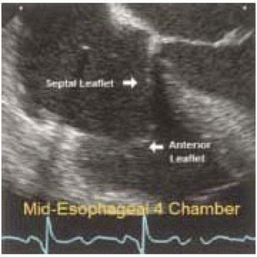 FIGURE 5.6. Midesophageal, four-chamber, two-dimensional image plane with focus on tricuspid valve. |
The chordae of the tricuspid valve originate from papillary muscles or directly from the muscle of the posterior or septal walls of the right ventricle. Silver et al. defined chordae as being rough zone, fan-shaped, basal, free edge, and deep chordae (8).
PULMONIC VALVE
The pulmonic annulus is not part of the fibrous skeleton as is the aortic annulus. It is attached to the base of the aorta by a flimsy fibrous extension of the aortic root called the tendon of conus. The rest of the pulmonic valve has muscular attachments to the right ventricle and interventricular septum (Fig. 5.7). The pulmonic valve normally has three cusps with a nodule at the midpoint of each free edge. The pocket behind the cusp is the sinus.
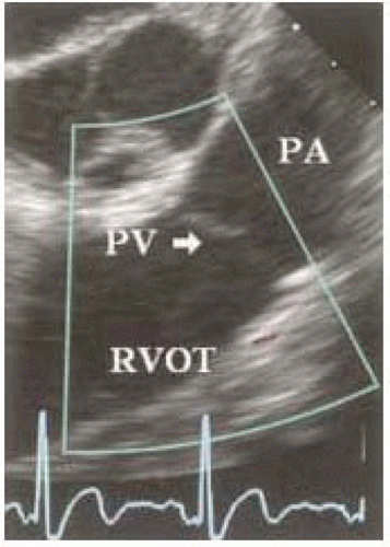 FIGURE 5.7. Midesophageal RV inflow-outflow two-dimensional imaging plane with focus on pulmonic valve. |
 FIGURE 5.8. The valve apparatus consisting of the mitral valve leaflets, chordae, papillary muscles, free wall of the left ventricle, and the mitral annulus. |
MITRAL VALVE APPARATUS
The mitral valve apparatus is an anatomical term describing structures of the left ventricle associated with mitral valve function (Fig. 5.8) (See also Chapters 14 and 28). These structures consist of the fibrous skeleton of the heart, the mitral annulus, mitral leaflets, mitral chordae, and the papillary muscle-ventricular wall complex. This anatomic description oversimplifies the complex mechanical interaction of the heart, which makes the left ventricular chamber functional.
The important role of TEE in mitral valve repair makes it imperative that the echocardiographer understands mitral valve anatomy. This understanding of anatomy is then used to define the mitral valve anatomy visualized by multiplane TEE imaging of the mitral valve. The echocardiographer must be able to communicate important anatomic/pathological findings to the surgeon performing a mitral valve repair. In addition to the anatomical terms for portions of the mitral valve, there are two surgical nomenclatures used: the Carpentier terminology (adopted by ASE/SCA) (5,7) and the Duran terminology (8,9). Ideally, the echocardiographer should be familiar with all of these terminologies (Fig. 5.9). Intraoperative echocardiographic identification of the different segments of the anterior and posterior mitral valve leaflets is dependent on understanding this terminology and their relation to the standard imaging planes (Figs. 5.10 and 5.11).
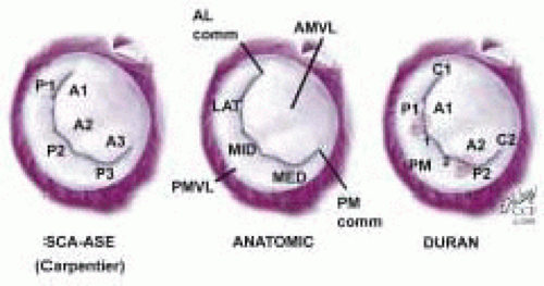 FIGURE 5.9. Comparison of SCA/ASE terminology with the anatomic nomenclature and Duran terminology. |
 FIGURE 5.10. Standard imaging planes and mitral valve anatomy. Imaging planes depicted above: Midesophageal four-chamber (ME 4Chr), midesophageal commissural, midesophageal two-chamber (ME 2Chr), midesophageal long axis (ME LAX). |
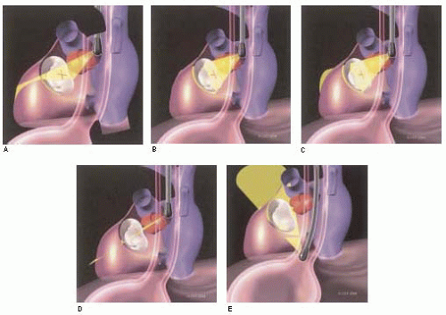 FIGURE 5.11. Three-dimensional illustration of relationship between TEE and mitral valve apparatus in imaging planes commonly used for three-dimensional evaluation of mitral valve. |
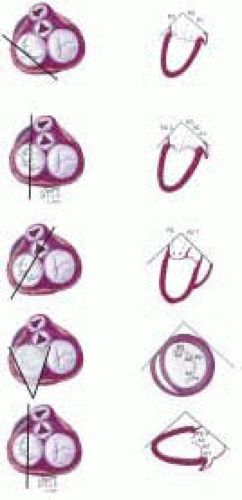 FIGURE 5.12. TEE-imaging planes and segmental mitral valve leaflet identification using SCA-ASE nomenclature. |
MITRAL VALVE LEAFLETS: CARPENTIER-SCA TERMINOLOGY
The Carpentier terminology is solely a terminology of the mitral leaflets and does not involve naming chordae or papillary muscles (7). The lateral scallop of the posterior leaflet is named P1, middle scallop named P2, and medial scallop named P3. The anterior leaflet is divided into A1, A2, A3 based upon the portion of the anterior leaflet making contact with P1, P2, and P3 during systole (Figs. 5.12, 5.13, and 5.14 and Table 28.2). The SCA/ASE terminology does not in fact define chordal attachment to the leaflets. However, it is important for the echocardiographer to understand the orientation of chordae as related to this terminology. For this purpose, their attachments are explained and related to the Carpentier terminology (Figs. 5.12, 5.13, and 5.14 and Table 28.2). The chordae tendineae are fibrous strings radiating from the left ventricular papillary muscles or the ventricular free wall (posterior leaflet only) and attaching to the mitral leaflets in an organized manner (10). Chordae from the papillary muscles radiate upward attaching to the corresponding halves of the anterior and posterior leaflets. Chordae arising from the anterior papillary muscle attach to A1, P1, (AC), and the lateral half of P2 and A2. Chordae arising from the posterior papillary muscle attach to A3, P3, (PC), and the medial half of P2, and A2 (Figs. 5.12, 5.13, and 5.14 and Table 28.2). This relation aids in defining the portion of the mitral valve that is echocardiographically visualized.
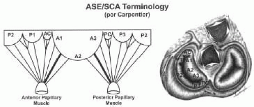 FIGURE 5.13. Chordal relationships—ASE/SCA terminology. Anterior leaflet divided into A1, A2, and A3. Posterior leaflet divided into P1 (anterolateral scallop), P2 (middle scallop), and P3 (posteromedial scallop). Commissural clefts not named anterior or posterior. Chordae arising from the anterior papillary muscle attach to A1, AC, and P1, and the lateral half of P2 and A2. Chordae arising from the posterior papillary muscle attach to A3, PC, and P3, and the medial half of P2 and A2. |
There are two chordae attaching to the ventricular surface of the anterior leaflet that are by far the thickest and largest of the chordae to the mitral valve. They have been called strut or stay chordae. One arises from the anterior papillary muscle and attaches to the A1/A2 area of the anterior leaflet; the other arises from the posterior papillary muscle and attaches to the A2/A3 portion of the anterior leaflet (Fig. 5.14).
Stay updated, free articles. Join our Telegram channel

Full access? Get Clinical Tree


