Fig. 4.1
Segmental approach to congenital heart disease (Reprinted with permission from O’Leary [7])
2.
When performing a TEE evaluation for CHD, particularly in patients with unknown or incompletely diagnosed anatomy, an organized methodology is essential so that all of the important information is obtained, and none is omitted. Whenever possible, it is preferable to perform as complete a study as possible, beginning each study in the same manner, and proceeding with a predefined and preplanned order of evaluation. However, this is not always feasible. In some instances, the exact order of examination will vary, first concentrating upon the most important information required, and then completing the remainder of the study. In other instances, a complete examination is not possible, or even necessary, and a more directed study is performed that focuses solely upon specific questions. Nevertheless, whether performing a focused or complete study, the examiner should always have in mind a mental checklist of the information required. Moreover, during the TEE examination, the examiner will note that, at any one time, a number of cardiac structures can often be visualized simultaneously. With so much information, some important details can easily be overlooked. This makes it even more important that the examiner maintain a mentally organized approach so that all essential information is obtained as methodically as possible.
3.
Sweeps are especially useful in the evaluation of complex CHD, as they provide important spatial information about the cardiac structure(s) in question. With transthoracic echocardiography, sweeps are routinely performed by probe angulation (left to right, superior to inferior, anterior to posterior, etc.). With TEE, different manipulations must be used to perform sweeps. These sweeps incorporate the basic manipulations of the TEE probe, e.g. advancing/withdrawing the probe slowly to/from the esophagus, rotating the probe shaft slowly in a clockwise/counterclockwise (right/left) direction, anteflexion/retroflexion of the probe tip, and rotation of the multiplane angle (see below). As with transthoracic echocardiography, the use of sweeps in TEE helps to build an understanding of the 3D anatomy of individual cardiac structures, as well as the complex interrelationships that sometimes exist between these structures. Many of the video examples in this chapter demonstrate various TEE sweeps.
Probe Orientation and Manipulation
After the TEE probe has been inserted into the esophagus, it can be manipulated in several different directions. For this description it is assumed that the patient is lying supine, with the examiner situated just superior to the patient’s head and facing the dorsum of the patient’s feet. Regarding orientation, superior is towards the patient’s head, inferior towards the stomach/feet, posterior towards the spine, anterior towards the sternum, and right and left towards the patient’s right and left sides, respectively.
The TEE probe can be manipulated as follows (Fig. 4.2). Pushing the probe more inferiorly (towards the stomach) is termed advancing the probe, pulling the probe more superiorly is called withdrawing the probe. Rotating the probe clockwise is called turning rightward or to the right, and counterclockwise is called turning leftward or to the left. Flexing the tip of the probe anteriorly (using the anteroposterior control wheel) is called anteflexion; flexing the tip posteriorly is called retroflexion. If there is a second control wheel for lateral tip movement, flexing the tip to the patient’s right and left is called flexing to the right and flexing to the left, respectively (right and left lateral movement controls are not as useful in pediatric patients, and not even included in many of the current pediatric TEE multiplane probes). Axial rotation of the multiplane angle of the probe (using either a mechanical or electronic control on the TEE probe handle) is described as rotating forward or back to x degrees, where x represents the multiplane angle. The multiplane angles will be shown as follows: at a multiplane angle of 0° (also known as the “horizontal” or “transverse” plane in biplane TEE imaging), the patient’s right side appears on the left of the image display (Fig. 4.3a). Rotating the multiplane angle forward to 90° results in an orthogonal plane also known as the “vertical” or “longitudinal” plane in biplane TEE imaging. This plane provides tomographic sections of the heart oriented in the patient’s sagittal plane. In this image, the left side of the screen is now the more inferior aspect (i.e. toward the patient’s feet), and the right side of the screen is the more anterior/superior aspect (Fig. 4.3b). Rotation beyond 90° continues to provide important and useful information, but eventually results in a mirror image of 0° at 180°, with the patient’s left side on the left of the screen (Fig. 4.3c). In general, the most useful TEE multiplane angles are obtained between 0° and 130°; it is rarely necessary (and potentially confusing) to use larger multiplane angles.
Fig. 4.2
Basics of probe manipulation during transesophageal echocardiography (TEE) (From Shanewise et al. [1], with permission from Elsevier)
Fig. 4.3
Image orientation with multiplane angles of 0°, 90°, and 180°. Transducer location and near field (narrow portion of image sector) of the image sector are at the top of the display; far field (wide portion of image sector) is at the bottom. (a) Multiplane angle of 0°; (b) Multiplane angle of 90°; (c) Multiplane angle of 180°. LA left atrium, LV left ventricle, RV right ventricle (From Shanewise et al. [1], with permission from Elsevier)
Cross-Sectional TEE Views for CHD Evaluation
While a standardized nomenclature has been well established for the transthoracic echocardiographic views and windows used in the evaluation of pediatric patients, specifically as pertains to CHD evaluation [6, 14], the same cannot be said for TEE. Only one previous textbook (published in 1994) exclusively addressed TEE evaluation of CHD [15]. At the time, this textbook served as an excellent resource, elaborating upon TEE views and techniques specifically applicable for CHD. However, it was written in the early era of biplane TEE imaging, while the technology was still evolving, and prior to the availability of multiplane TEE transducers for pediatric applications. In fact most of the examples in that textbook were obtained from single plane (transverse) imaging. As biplane TEE became more widespread, several subsequent journal articles expanded upon its use in CHD evaluation [16–18]. With the increasing adoption of multiplane TEE imaging for adult patients, in 1999 the American Society of Echocardiography/Society of Cardiovascular Anesthesiologists (ASE/SCA) published guidelines for a standardized nomenclature pertinent to multiplane TEE probe manipulation, orientation and imaging. A series of 4 principal transducer locations (windows) and 20 anatomically directed cross-sectional tomographic views were defined [1]. These guidelines represented a significant contribution, and have since become widely accepted and employed for the standard performance of TEE [19]. While thorough and very extensive, they were nonetheless written primarily for the examination of the adult patient with an anatomically normal heart, with a focus upon evaluation of left ventricular function and mitral valve anatomy/function. However, since widespread availability of pediatric multiplane TEE probes did not occur until several years after the guidelines were published, comparable standardized guidelines have not been written specifically for the multiplane TEE evaluation of CHD, although several excellent articles have discussed the use of the ASE/SCA views/nomenclature for this purpose [20–22]. Of note, even the ASE guidelines for TEE in pediatric patients with congenital or acquired heart disease—authored by the ASE pediatric council—mentioned the ASE/SCA guidelines but gave no specific recommendations regarding the TEE views and methods needed for CHD evaluation. This article acknowledged the fact that no uniform consensus exists on standardized views and planes to be used for the TEE examination in the pediatric patient [20].
In this chapter, we present the ASE/SCA guidelines as they are suitable for the evaluation of CHD. In addition, we will expand upon the guidelines by presenting a modified version of the terminology/images and transducer windows that are essential or may complement the examination in this unique patient group. These modifications were designed and organized to facilitate their use for CHD evaluation. In this way, readers of the textbook will have a standardized “toolbox” of terms, views, and nomenclature that can be used as a reference for subsequent chapters in the textbook.2
TEE Transducer Locations and Views Used Throughout This Textbook
We define five principal TEE transducer locations, or windows—the upper esophageal, mid esophageal, lower esophageal, transgastric and deep transgastric, as shown in Fig. 4.4. These windows correspond to those used in the ASE/SCA guidelines, with the exception of the lower esophageal window, which was added for this textbook. For each of these windows, there are several typical or common views, each with a name describing the type of structure or view imaged, and some accompanied by the designation of “short” vs. “long” axis orientation (Fig. 4.5). Table 4.1 provides a listing of the individual cross-sectional views shown in Fig. 4.5, along with the abbreviation for each view, multiplane angle range, and structures imaged. We have also included several additional views that are not part of the original ASE/SCA guidelines—views that are useful for the evaluation of CHD. These additional views are designated with an asterisk. The specific images in Table 4.1 and Fig. 4.5, and their application, will be discussed in greater detail below.
Fig. 4.4
The five basic windows for TEE evaluation. For simplicity, each view is shown with the multiplane angle at 0°. UE upper esophagus, ME mid esophagus, LE lower esophagus, TG transgastric, DTG deep transgastric
Fig. 4.5
Representative cross-sectional views showing the main structures displayed from each of the five principal windows. Approximate multiplane angle is indicated by the icon adjacent to each view. Views modified from the original ASE/SCA statement are given the designation (mod). Views not part of the original ASE/SCA statement, and added as additional views for this textbook, are denoted with an *. In some views, two images are shown depicting the changes that occur with probe manipulation; the specific probe maneuvers are shown in between the images. See text and Table 4.1 for further details. Ao aorta, Asc ascending, AV aortic valve, Desc descending, DTG deep transgastric, In-Out inflow-outflow, IVC inferior vena cava, LAX long axis, LE lower esophageal, ME mid esophageal, PA pulmonary artery, RV right ventricle, SAX short axis, TG transgastric, UE upper esophageal (Modified from Shanewise et al. [1], with permission from Elsevier)
Table 4.1
Recommended transesophageal echocardiography cross sections
Window | Cross section (see Fig. 4.5) | Abbreviation | Multiplane angle range | Structures imaged |
|---|---|---|---|---|
Upper esophageal (UE) | Aortic arch long axis (a) | UE Ao Arch LAX | 0° | Aortic arch, Inn v |
Pulmonary artery long axis (b)* | UE PA LAX | 0° | PA bifurcation, LPA, RPA, PDA | |
Aortic arch short axis (c)◊ | UE Ao Arch SAX | 90–100° | Aortic arch, MPA, LPA, PDA, PV, Inn v | |
Mid esophageal (ME) | Four chamber (d) | ME 4 Ch | 0–20° | LV, LA, LAA, RV, RA, RAA, MV, TV, IAS, AV, CS |
Mitral commissural (e) | ME Mitral | 60–70° | MV, LV, LA | |
Two chamber (f) | ME 2 Ch | 80–100° | LV, LA, LAA, MV, CS | |
Long axis (g) | ME LAX | 100–130° | LV, LA, AV, LVOT, MV, Asc Ao, IVS | |
RV inflow-outflow (h) | ME RV In-Out | 60–90° | RV, RA, TV, RVOT, PV, MPA, IVS | |
AV short axis (i) | ME AV SAX | 30–60° | AV, IAS, coronary origins, LVOT, PV | |
AV long axis (j) | ME AV LAX | 90–130° | AV, LA, LV, LVOT, MV, prox Asc Ao, RPA | |
Bicaval (k) | ME Bicaval | 80–110° | RA, RAA, SVC, IVC, IAS, LA | |
Asc aortic short axis (l) | ME Asc Ao SAX | 0–60° | Asc Ao, SVC, MPA, RPA | |
Asc aortic long axis (m) | ME Asc Ao LAX | 90–120° | Asc Ao, RPA, MPA | |
Desc aorta short axis (n) | Desc Ao SAX | 0° | Desc thoracic Ao, left pleural space | |
Desc aorta long axis (o) | Desc Ao LAX | 90–110° | Desc thoracic Ao, left pleural space | |
Lower esophageal (LE) | Situs short axis (p)* | LE Situs SAX | 0–10° | IVC, Eustachian valve, RA, CS |
IVC long axis (q)* | LE IVC LAX | 70–100° | Hepatic veins to IVC, RA, Eustachian valve, lower portion of IAS | |
Transgastric (TG) | Basal short axis (r) | TG Basal SAX | 0–20° | LV, MV, RV, TV |
Mid short axis (s) | TG Mid SAX | 0–20° | LV, RV, pap mm, IVS | |
Two chamber (t) | TG 2 Ch | 80–100° | LV, MV, LA, LAA, chordae, pap mm, CS | |
Long axis (u) | TG LAX | 90–120° | LVOT, AV, MV, Asc Ao | |
RV inflow (v) | TG RV In | 100–120° | RA, RV, TV + chordae, pap mm, SVC inflow | |
Deep transgastric (DTG) | Long axis (w)◊ | DTG LAX | 0–20° (anteflexion) | LVOT, AV, Asc Ao, IAS, IVS, MV, TV, RA, LA, RV, LV, RVOT, PV |
Sagittal (x)* | DTG Sagittal | 80–110° (anteflexion) | LVOT, RVOT, AV, PV, MPA, MV, TV, IAS, IVS, RV, LV, RA, LA, SVC inflow (modified) |
Image Display Conventions Used Throughout This Textbook
The reader will note that several TEE views are comparable to those obtained by standard transthoracic evaluation, and they are displayed in a similar manner (e.g. the four chamber view). However other TEE views are unique and/or oriented quite differently from their transthoracic counterparts. It is important to acknowledge that some variation exists among different CHD centers as to how these views should be displayed (e.g. some centers display, anterior structures at the top of the screen and inferior ones at the bottom), and this has led to some controversy. To minimize confusion and facilitate reader comprehension, images in this textbook will be displayed as per the convention of the ASE/SCA guidelines: with posterior anatomic structures closer to the imaging probe and in the near field (narrow portion or apex of the image sector) at the top of the screen, and the far field structures (wide portion of the image sector) at the bottom [1]. The only exceptions to this image display are the deep transgastric views, which will be shown inverted, with the apex of the heart at the bottom of the screen (right/left orientation remains the same), thereby presenting an “anatomically correct” image of the heart [23, 24].
Structural Evaluation of CHD by TEE
What follows below is a suggested methodology for a comprehensive TEE study that can be performed in most patients, utilizing both the ASE/SCA standard views as well as the additional modified views and nomenclature outlined above. This approach yields a detailed anatomic assessment of the heart, guided by the principles of segmental analysis. For each area of the heart, suggested probe position and view(s) are given in order to provide an optimal assessment of the structure(s) in question. It should be noted that subsequent chapters in this textbook will provide further details and elaboration of the TEE assessment discussed below, specifically pertaining to the normal and abnormal anatomy covered in that particular chapter.
The TEE examples shown in this chapter are taken almost exclusively from patients with normal cardiac position (levocardia) and normal cardiac anatomy, but the principles of examination embodied in these examples apply equally to any patient with simple or complex CHD. Obviously, the individual views given in Table 4.1 and Fig. 4.5 should be considered only as a starting point, or point of reference, for CHD evaluation. During the course of a study a number of modifications in probe position, probe rotation, and multiplane angle will generally be required to visualize different cardiac structures, particularly in patients with complex anatomy, cardiac malposition, or unusual relation of the esophagus to the heart. In some cases, optimal visualization of a given cardiac structure will require deviation (sometimes significant) from the multiplane angle and image views listed in Table 4.1; some images will bear little, if any, resemblance to the views presented in Fig. 4.5. As readers peruse this textbook, they will undoubtedly encounter sections in which the layout of the specific anatomy being discussed does not fully comport with the named views defined in this chapter—for example, using a “mid esophageal four chamber view” in a patient with double inlet left ventricle (only three main chambers), or a “mid esophageal aortic valve long axis view” when the patient has aortic valve atresia. What is most important for the reader to recognize is that CHD evaluation is a structure-based, not view-based, approach, and that it is the information contained within a view—not its name—that must be understood. With this in mind, throughout the textbook we will continue to utilize, as much as possible, the nomenclature and views as defined in this chapter. Maintaining a consistent approach and terminology will, we believe, assist the reader in fully understanding the specific methods of TEE evaluation described by the authors in their respective chapters. We strongly encourage the reader to become familiar with all of the views and nomenclature presented herein, and to refer to this chapter frequently if clarification is needed.
As mentioned previously, the confinement of the TEE probe to the esophagus leads to inherent limitations in the imaging of certain intra and extracardiac structures. Simply put, there are some structures and defects that TEE images well, and some that it does not. These limitations will be noted in this and subsequent chapters.
Initiation of TEE Study, Establishment of Atrial Situs and Systemic/Pulmonary Venous Return
This approach starts the TEE study with the probe in a neutral position facing anteriorly, in the mid esophageal position, with a multiplane angle of 0–10°. This produces the mid esophageal four chamber view (ME 4 Ch), which is the TEE equivalent of a standard transthoracic apical four chamber view (Figs. 4.5d and 4.6). Since it is readily recognizable, this view can be used for orientation, thereby serving as the “home base” view for the examination. The ME 4 Ch also serves to identify the base to apex orientation of the heart: levocardia (apex to the left), mesocardia (apex midline), and dextrocardia (apex to the right). Because of the esophageal location for TEE, it can be difficult to ascertain the exact position of the heart in the thorax, but in many cases the base to apex orientation corresponds with the cardiac position [9]. It is important to verify the right/left orientation of the image display and confirm this with rotation of the probe to the right and left; an incorrect setting can complicate the examination, for example by making a patient with levocardia appear to have dextrocardia. Once this view is obtained and the examiner oriented, image settings can be optimized, and the study commences. If the examiner becomes disoriented by movement of the probe to an unfamiliar location, and/or by visualization of unfamiliar structures, the TEE probe can be returned to this “home base” position for reorientation.
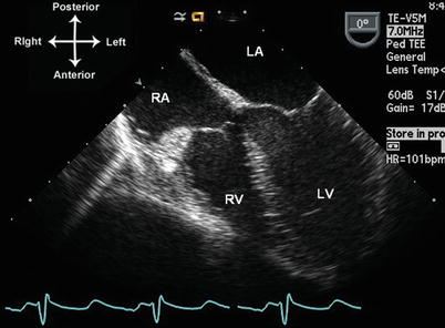
Fig. 4.6
Mid esophageal four chamber, or “home base” view. Multiplane angle is 0–10°. LA left atrium, LV left ventricle, RA right atrium, RV right ventricle
The TEE study should begin with an evaluation of visceroatrial situs. This is an important and often overlooked part of the TEE examination for CHD. Visceral and atrial situs are almost always concordant [12], so atrial situs evaluation can be used. Atrial situs is either solitus, inversus, or ambiguous. In situs solitus (normal), the morphologic right atrium (RA) is located to the right of the morphologic left atrium (LA). In situs inversus, there is left-right reversal of the two, and in situs ambiguous (heterotaxy) there is atrial isomerism. By TEE, atrial situs can be determined by several methods. The characteristic features of the atrial appendages serve to distinguish the morphologic RA and LA. The right atrial appendage is typically triangular and broad based, while the left atrial appendage is long and tubular, with a narrow base [8]. In cases of atrial isomerism (heterotaxy, or situs ambiguous), two atrial appendages of the same morphology will usually be seen, presenting as mirror images of each other. Atrial appendage morphology can be readily identified by TEE [25]; the individual appendages can be seen using a combination of mid esophageal views including the mid esophageal bicaval, four and two chamber views (described below). Another important atrial structure, the atrial septum, can also help to establish atrial situs. The atrial septum is comprised of two individual components: the thicker septum secundum (comprised of superior and inferior limbic bands, or limbus), and the thinner septum primum, also known as the valve of the foramen ovale. The septum secundum forms the right atrial surface of the atrial septum, and the septum primum forms the left atrial surface. Therefore in normal atrial situs (solitus), the septum secundum should be located to the right of septum primum; the reverse holds true with atrial situs inversus (the atrial septum is often very deficient in situs ambiguous). When an atrial septum is present, its two components are readily visualized by several mid esophageal TEE views, as will be discussed below.
Atrial situs can also be established by visualization of the suprahepatic portion of inferior vena cava (IVC) and coronary sinus (CS) drainage. These two structures, when present, usually drain into the morphologic RA [26, 27]. Given the postero-inferior position of both structures, the best method to image these is by using a lower esophageal/transgastric window. Therefore from the “home base” (ME 4 Ch) position, the TEE probe is advanced into the stomach and anteflexed, using a multiplane angle of approximately 0° and slight rightward turning of the probe. The hepatic veins (HVs) can be visualized, as well as IVC. The probe is slowly withdrawn, and the HVs will be seen to drain into the IVC in the view that we will refer to as the lower esophageal situs short axis view (LE Situs SAX, Figs. 4.5p and 4.7a). In the same probe location, rotating the multiplane angle to 80–100° and turning the probe rightward (clockwise) visualizes the lengthwise extent of the IVC as it courses through the liver in the lower esophageal IVC long axis view (LE IVC LAX, Figs. 4.5q and 4.7b). This view is useful to distinguish the IVC from prominent HVs, which in some views can mimic the appearance of the IVC. The length of the Eustachian valve can be seen in this view. Rotating back to a multiplane angle of 0°, the probe is withdrawn further (continuing anteflexion to maintain contact with the stomach wall and esophagus), and the IVC can then be seen entering into the right atrium (Fig. 4.8a). Video 4.1 demonstrates this short sweep using nearly orthogonal multiplane angles between 0° and 90°. At this point, or with a small amount of probe withdrawal and retroflexion, the CS can be seen entering into the RA (Fig. 4.8b). Eustachian valve tissue is often seen at the mouth of the IVC, sometimes in continuity with the Thebesian valve of the coronary sinus. The diameter of the coronary sinus opening into the RA is often quite small, except in the presence of a left superior vena cava (LSVC) draining into the CS. The CS is located posteriorly and inferiorly in the heart, and therefore best visualized in its long axis from the lower esophageal window (LE Situs SAX) or the ME 4 Ch view, using a multiplane angle of 0°. Retroflexion of the probe sometimes enables the entire length of the CS to be seen. When the CS is dilated, its margins might not be as well defined, and sometimes a large CS can be confused for a large primum or secundum atrial septal defect. However the CS is more posterior and inferior than either of these defects. A dilated CS is mainly seen when an LSVC is present and drains to the CS; however it can be seen in other conditions as well. A lengthwise view of the dilated CS is best displayed with a multiplane angle of 0–10° (Fig. 4.9).
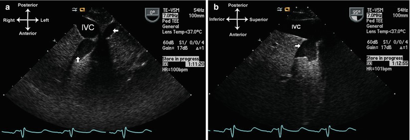
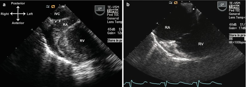
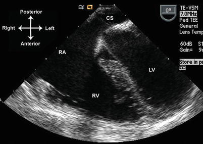
Fig. 4.7
Hepatic veins entering into the inferior vena cava (IVC) from the lower esophageal situs short axis view with a multiplane angle of 0° (a) and the lower esophageal IVC long axis view with a multiplane angle of 95° (b). The arrows show hepatic veins entering the IVC
Fig. 4.8
Entrance of inferior vena cava (IVC) (a) and coronary sinus (b) into the right atrium using lower esophageal situs short axis view. Arrows in (a) point to the Eustachian valve. RA right atrium, RV right ventricle
Fig. 4.9
Dilated coronary sinus seen from the mid esophageal four chamber view. CS coronary sinus, LV left ventricle, RA right atrium, RV right ventricle
Once the TEE probe is back in the mid esophageal position, further evaluation of systemic and pulmonary venous return can be undertaken. To visualize a right-sided superior vena cava (the normal position for this vessel in situs solitus, abbreviated as SVC in this chapter), the probe is withdrawn further using slight anteflexion and turning to the right, with a multiplane angle of 0–10° (Fig. 4.10). The entrance of the SVC to the right atrium can be seen in cross section. With further probe withdrawal, more superior portions of the SVC can be seen although this area is not consistently visualized in all patients. Returning to right atrial level, rotation of the multiplane angle to 80–100° yields a sagittal view known as the mid esophageal bicaval view (ME Bicaval, Figs. 4.5k and 4.11, Video 4.2), showing the SVC and IVC entrances to the RA as well as the right atrial appendage. If an LSVC is present, it can also be visualized at this level by rotating the probe leftward (counterclockwise), while maintaining a multiplane angle of 80–100°. This provides a lengthwise, long axis view of the LSVC (Fig. 4.12, Video 4.3). Keeping the probe in the same position and rotating the multiplane angle to 0–10° produces a cross-sectional, short axis view of the LSVC. In both long and short axis views, the LSVC can sometimes be visualized quite superiorly, at the level of the upper esophagus. From this position, by advancing the TEE probe from the upper to mid esophageal position, a superior to inferior sweep of the LSVC can be performed as it descends to its insertion into the dilated CS (Video 4.3). It should be remembered that a LSVC, when present, generally drains through a dilated CS to the RA. However, occasionally it can return directly to the LA, and in these instances the CS will usually not be dilated.
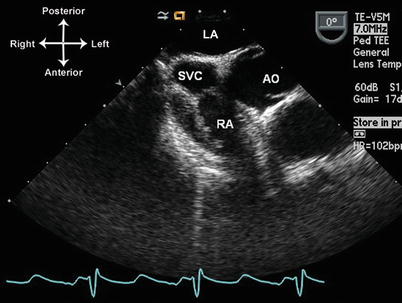
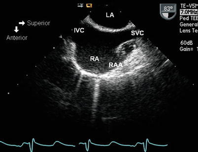
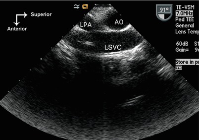
Fig. 4.10
Superior vena cava (SVC) entrance into the right atrium (RA) as seen from the mid esophageal level, multiplane angle of 0° and with rightward turning of the probe. AO Aorta; LA left atrium
Fig. 4.11
Mid esophageal bicaval view, obtained with a multiplane angle between 80° and 90°. IVC inferior vena cava, LA left atrium, RA right atrium, RAA right atrial appendage, SVC superior vena cava
Fig. 4.12
Left superior vena cava (LSVC) returning to the coronary sinus. The LSVC courses anterior to the left pulmonary artery (LPA). The probe tip is located between mid and upper esophageal window, turned to the left, and the multiplane angle is approximately 90°. In this patient there is an absent right SVC, with the innominate vein returning to the right atrium via the LSVC and dilated coronary sinus. A catheter is seen in the LSVC. Ao transverse aortic arch
Evaluation of pulmonary venous drainage is one of the strengths of TEE. The close proximity of the LA and pulmonary veins to the esophagus not only provides superior imaging, but also an excellent Doppler color flow signal and favorable angles for spectral Doppler analysis. It is often helpful to utilize color flow mapping to aid assessment of the pulmonary veins. However, lowering of the Nyquist limit (to 30–60 cm/s) is sometimes necessary to visualize an optimal color flow signal.
The individual right and left pulmonary veins can be separately assessed by TEE, although slightly different views and techniques are required for each side [28, 29]. The right pulmonary veins are best evaluated using the ME 4 Ch view, turning the TEE probe to the right to visualize the lateral border of the RA. Advancing the probe and turning to the right enables visualization of right lower pulmonary vein, which takes a more horizontal course on the display (Fig. 4.13a, Video 4.4). With slow withdrawal and slight turning of the probe to the left, the right upper (and sometimes right middle) vein can be readily seen; these veins take a more vertical course on the display as they enter the RA (Fig. 4.13b, Video 4.4). The left pulmonary veins have a slightly different drainage pattern. There are generally two left pulmonary veins (upper and lower), and their sites of return to the LA are usually very close together (or even the same site). The left pulmonary veins can be identified by the ME 4 Ch view, with a multiplane angle of 0–10° and leftward (counterclockwise) turning of the probe. With these settings, slight advancing and withdrawing of the probe is necessary to visualize the individual pulmonary veins. Like the right pulmonary veins, the left lower pulmonary vein has a slightly more horizontal course on the display, and the left upper vein takes a more vertical course (Fig. 4.14a, b, Video 4.4). Both the right and left pulmonary veins can also be visualized from an orthogonal, sagittal (longitudinal) view, effectively a ME Bicaval view with the probe multiplane angle anywhere between 50° and 100°. With this type of evaluation, it is best to visualize first the LA and then rotate the probe rightward or leftward (clockwise/counterclockwise) to visualize the pulmonary veins on either side (Fig. 4.15a, b). These views provide an excellent display of the individual lobar veins as they enter the LA.
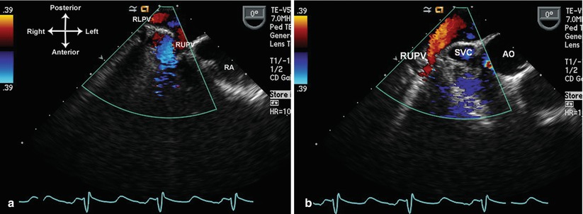
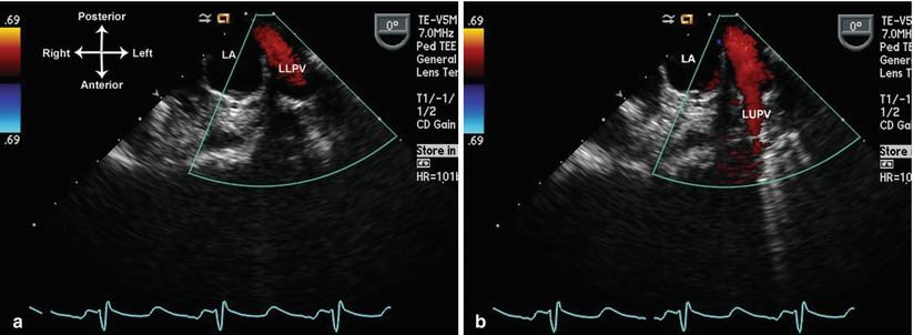
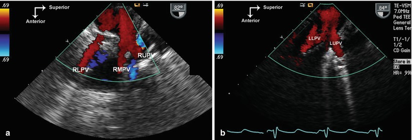
Fig. 4.13
Right pulmonary veins displayed by color Doppler as they enter into the left atrium. The lower (a) and upper pulmonary veins are seen (a). The right upper pulmonary vein is depicted as it courses in longitudinal fashion behind the superior vena cava (b). These images were obtained at a multiplane angle of 0° with probe turned slightly to the right. The Nyquist limit was lowered to optimize identification of these structures. AO aorta, RLPV right lower pulmonary vein, RUPV right pulmonary vein, SVC superior vena cava
Fig. 4.14
Left lower (a) and upper (b) pulmonary veins shown as these return to the left atrium. Images obtained at a multiplane angle of 0°, probe turned slightly to the left. LA left atrium, LLPV left lower pulmonary vein, LUPV left upper pulmonary vein
Fig. 4.15
Right and left pulmonary veins returning to the left atrium as viewed from a sagittal (90°) plane. The probe tip is at mid esophageal level, first turning to the right to visualize the right pulmonary veins (a), and then to the left to visualize the left pulmonary veins (b). LLPV left lower pulmonary vein, LUPV left upper pulmonary vein, RLPV right lower pulmonary vein, RMPV right middle pulmonary vein, RUPV right upper pulmonary vein
It is important to remember that, due to the frequency of anomalous pulmonary venous drainage anomalies seen with CHD, pulmonary venous drainage cannot be relied upon to determine atrial situs. Abnormalities of pulmonary venous drainage are discussed in Chap. 6.
Atria and Atrial Septum
The atria and atrial septum are best visualized from the lower and mid esophageal views. A combination of sweeps is generally used. The first sweep begins in the lower esophagus, with a multiplane angle of 0° and a view of the mouth of the IVC entrance to the right atrium. The probe is gradually withdrawn so that the CS and inferior limbic band of atrial septum secundum come into view. Any defects in the posterior atrial septum can be visualized. With further probe withdrawal to the mid esophagus, both atria are well seen, as well as the thin atrial septum primum, and with slightly more rightward rotation, the right atrial appendage (Fig. 4.16a, Video 4.5). As the probe is withdrawn further, superior limbic band of septum secundum becomes visible, as well as the entrance of the SVC into the RA (Fig. 4.16b, Videos 4.5 and 4.6). The right pulmonary veins can be shown returning to the LA (as described above), along with their relationship to the atrial septum. From here, leftward probe rotation and slight probe anteflexion, as well as variation of the multiplane angle between 0° and 60°, will display the left atrial appendage (with its typical finger-like shape) just anterior to the left upper pulmonary vein (Fig. 4.17, Video 4.7).
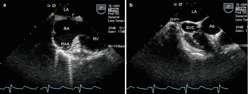
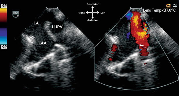
Fig. 4.16
Atrial septum visualized from the mid esophagus, with multiplane angle 0°. In (a) the probe is rotated to the right, showing both right atrium (RA) and left atrium (LA) and the thin atrial septum primum (arrow) located to the left of septum secundum. The right atrial appendage (RAA) is also visible. In (b) withdrawal of the probe demonstrates the superior limbic band of septum secundum, along with the entrance of the superior vena cava (SVC) into the RA, just anterior to the entrance of the right upper pulmonary vein (RUPV) to the LA. Ao aorta, RV right ventricle
Fig. 4.17
Visualization of the left atrial structures. In the mid-esophageal view, with leftward turning of the probe as well as slight anteflexion and a multiplane angle of 25°, the left atrium (LA), left atrial appendage (LAA), and left upper pulmonary vein (LUPV) are seen. Color Doppler facilitates the identification of the left pulmonary veins
An orthogonal, sagittal sweep is then performed by setting the multiplane angle to 80–90° and obtaining the ME Bicaval view. The SVC and IVC entrances to the RA, the posterior LA, as well as the right atrial appendage, are well seen (Fig. 4.11, Video 4.5). Rightward turning of the probe visualizes the right pulmonary veins (as noted above); slow leftward turning of the probe back to the ME Bicaval view visualizes the return of these veins back to the LA. The atrial septum is also very well shown with this sweep (Figs. 4.11 and 4.18, Videos 4.2 and 4.5). A patent foramen ovale, when present, is usually seen as a small flap in the atrial septum between its two components of septum secundum and septum primum. Atrial shunting can be confirmed by color flow Doppler (Fig. 4.19, Video 4.8). With further leftward turning of the probe, the remainder of atrial septum (including posterior rim) is visualized, and eventually the entire LA is displayed. A cross section of the CS is then visualized inferiorly. With even more leftward turning, the left atrial appendage and left pulmonary veins come into view (as described above).
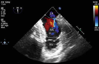
Fig. 4.18
Mid esophageal bicaval view shows the thin septum primum component of the atrial septum, located posterior and to the left of the thicker atrial septum secundum. LA left atrium, RA right atrium
Fig. 4.19
Mid esophageal bicaval view with leftward probe rotation demonstrating a small patent foramen ovale with left to right shunting. LA left atrium, RA right atrium, RV right ventricle
If the atrial septum appears intact but atrial shunting is still suspected, a contrast injection can be performed through a peripheral or central vein, using agitated saline [30–32]. Contrast injection can often uncover small, occult right to left atrial level communications. Video 4.9a shows no right to left shunt atrial level shunt, Video 4.9b shows an occult right to left atrial shunt. However, it should be remembered that even with contrast injection, some atrial communications with potential for shunting could still go undetected [33, 34]. In older patients in whom TEE is performed under conscious sedation, provocative maneuvers such as a Valsalva maneuver [30] or coughing [31, 35] have been recommended in conjunction with contrast injection. In patients who are intubated, a simulated Valsalva maneuver can be performed by manually inflating the lungs with positive inspiratory pressure to about 25 mmHg for 10 s [36], maintaining inflation while injecting contrast, and then allowing the lungs to deflate as contrast is seen filling the heart.
Abnormalities of the atria and atrial septum are very well visualized by TEE. For this reason, TEE is widely used to evaluate atrial septal defects (including during transcatheter closure), atrial septal aneurysms, atrial masses and atrial/left atrial appendage thrombi. These applications will be discussed in subsequent chapters of this textbook.
Atrioventricular Valve Evaluation
Evaluation of the atrioventricular (AV) junction represents a key aspect of segmental analysis. Because the atrial and ventricular segments are independent of each other, different combinations can occur in the connection between the atria and ventricles [5, 12]. Normally, the RA empties into the morphologic right ventricle (RV) and LA into the morphologic left ventricle (LV), and this is termed AV concordance. However, when the RA empties into LV and LA into RV, there is AV discordance—as seen in congenitally corrected transposition of the great arteries (CCTGA). With two good-sized AV valves and ventricles, the general rule is that the AV valves arise from (and are associated with) their ventricle of entry, not the atrium of exit [37, 38]. Thus the AV valve associated with the morphologic LV is generally the mitral valve, and with the morphologic RV, the tricuspid valve. However, abnormalities of AV connection can occur that cause deviations from this rule, including override or straddling of one AV valve into another chamber, and connection of both AV valves to one ventricle (double inlet ventricle). In addition, other abnormalities can also occur such as absence of an AV valve (tricuspid/mitral atresia), and a common AV valve (AV septal or canal defect) [5, 8, 37]. When evaluating CHD, it is important for the TEE examiner to be mindful of these different possibilities. Nonetheless, the evaluation of the AV connections can be distilled into several important components. The first is, of course, correct morphologic identification of the individual atria (discussed above) and ventricles (discussed below) [8]. Once this is established, details of the AV connections can be determined, including: AV valve identification and number (one vs. two), how the atria and ventricles are connected, any possible override/straddling of the AV valves, and whether AV valve stenosis and/or insufficiency is present. For this type of evaluation, TEE generally provides excellent information.
Stay updated, free articles. Join our Telegram channel

Full access? Get Clinical Tree


