Rate-adaptive pacing has been a mainstay of bradycardia pacing programming for many years. The hemodynamic advantages of rate-adaptive modes, i.e., VVIR vs. VVI, AAIR vs. AAI, and DDDR vs. DDD, have been recognized since very early in the rate-adaptive pacing experience. Similarly, when dual-chamber rate-adaptive pacing was introduced, literature emerged demonstrating hemodynamic superiority of DDDR over DDD in the chronotropically incompetent patient. Rate-adaptive pacing may be similarly beneficial with cardiac resynchronization therapy (CRT) devices. Although there are other benefits of rate-adaptive pacing, correcting the chronotropic response remains the most important.
Indications for Rate-Adaptive Pacing
The indications for rate-adaptive pacing are relatively straightforward (also reviewed in Chapter 2: Hemodynamics of Cardiac Pacing). VVIR pacing is indicated primarily for the patient with chronic atrial fibrillation and a slow ventricular response that requires bradycardia support. AAIR, not widely used, is appropriate for the patient with sinus node dysfunction and intact atrioventricular (AV) node conduction. Even though a significant number of patients require permanent pacing for sinus node dysfunction, many clinicians remain uncomfortable with a system that does not provide ventricular pacing support.
Chronotropic incompetence also remains the primary indication for DDDR pacing. However, pulse generators with the option of rate-adaptive pacing are reasonable to consider for any patient requiring dual-chamber pacing because of the clinical flexibility it may provide in the future. For example, should atrial fibrillation develop in a patient with a dual-chamber rate adaptive pacemaker, the pacemaker can be programmed to a single-chamber rate-adaptive mode, i.e., VVIR. In addition, if the patient has symptoms with traditional DDD upper rate response, i.e., symptomatic 2 : 1 AV block, optimal programming of sensor response in a DDDR pacemaker will minimize V-V cycle length variation.
Sensors Available for Rate-Adaptive Pacing
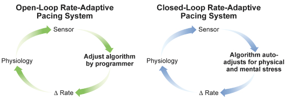
Sensors can also be classified as open-loop or closed-loop (Fig. 9.1). All commercially available sensors are open-loop sensors to some extent, in that the parameter being sensed requires input externally to optimize sensor response, and the sensor is unable to react appropriately to stimuli that do not affect the specific sensor. Conversely, a closed-loop system ideally does not require external input or manipulation because intrinsic feedback to the sensor self-regulates its response.
Fig. 9.1 Open-loop and closed-loop sensors. In the open-loop design, the parameter detected by the sensor is translated to a change in rate by use of an algorithm. Altering or optimizing the sensor requires input by the clinician. The rate change that results from the sensor activation does not have any negative feedback effect on the parameter that is being sensed. In the closed-loop design, the physiologic parameter, ideally both physical and mental, detected by the sensor is translated to a change in rate by use of an algorithm. However, the rate change resulting from sensor activation results in a change in the physiologic parameter in the opposite direction, i.e., a negative feedback loop. For a true closed-loop sensor, clinician input should not be necessary; that is, the ideal physiologic parameter that responds proportionally to all forms of stress should not need external input or manipulation by the clinician.
The ideal closed-loop sensor should closely mimic the normal sinus node and not require external input for programming. To mirror normal sinus node function, the sensor should have an anticipatory increase in heart rate prior to activity, increase the heart rate in proportion to the intensity of activity, gradually allow heart rate to return to normal after cessation of activity, and respond to nonphysical exertion (emotion). These characteristics of the ideal sensor are summarized in Table 9.1.
Table 9.1 Characteristics of the ideal rate-adaptive sensor.
|
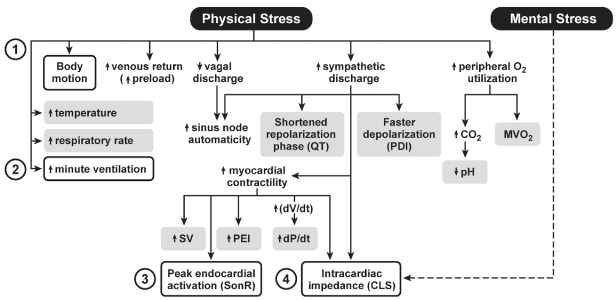
A variety of sensors appropriate for rate-adaptive pacing have been developed and clinically assessed; they are displayed in Fig. 9.2 as end-points of some physiologic response. Only a few of these sensors are clinically available. Others have previously been investigated and subsequently abandoned commercially. Even though some sensors may never have been clinically released as single-sensor rate-adaptive pacing systems, some iteration of the sensor technology may eventually be used for hemodynamic autoregulation in CRT or stand-alone implantable diagnostic devices.
Fig. 9.2 Physiologic responses that have been investigated or clinically used for rate adaptation of permanent pacemakers. The boxed terms represent the end-points used for rate adaptation. PDI, paced depolarization integral; PEI, pre-ejection interval; MVO2, myocardial oxygen consumption; SV, stroke volume.
Two varieties of sensors account for most rate-adaptive pacing systems worldwide. Activity sensing and minute ventilation have been the primary rate-adaptive pacing systems in the USA and have also been widely used throughout the world. Stimulus-T, or QT, sensing pacemakers as well as an impedance-based sensor have been used less extensively but are currently in use. In some markets outside the USA another type of accelerometer is used that is incorporated into the tip of the pacing lead, originally known as “peak endocardial accelerating.”
Activity Sensors
Piezoelectric Crystal (Vibration Sensor)
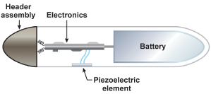
Activity-controlled pacing with vibration detection remains the most widely used form of rate adaptation because it is simple, easy to apply clinically, and rapid in onset of rate response (Fig. 9.3). The piezoelectric crystal is bonded to the inside wall of the pulse generator can. As the body moves and generates low-frequency vibrations that are transmitted to the torso, the piezoelectric crystal is slightly deformed. With the slight deformation the piezoelectric crystal produces a weak electrical current, which is then used as the basis of the algorithm to adjust the pacing rate.
Fig. 9.3 Schematic drawing of how an activity sensor using a piezoelectric crystal is positioned within the pulse generator. The piezoelectric sensor was bonded to the inside surface of the pacemaker can and senses tissue vibration from mechanical forces transmitted by the surrounding tissues.
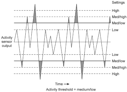
The generated electrical currents from the piezoelectric crystal are “counted” based on the size of the output and whether it is large enough to cross a specified threshold. The number of outputs counted, i.e., the number that will meet criteria to alter the heart rate, is therefore a function of both the “size” of the signal (in turn dependent on the extent of movement) and the sensitivity to which the sensor threshold is programmed (Fig. 9.4).
Fig. 9.4 Signals from a piezoelectric crystal. Various sized signals will be acted upon based on how the threshold of the sensor is programmed and whether a given signal or oscillation crosses the sensor threshold.
(Redrawn from Medtronic, Adapta Technical Manual, pp. 2–15, with permission.)
Accelerometer (Acceleration Sensor)
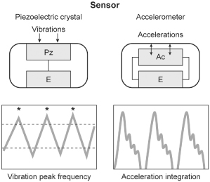
The main difference between the piezoelectric crystal sensor and the accelerometer relates to the way in which the sensor is mounted within the pacemaker as well as the way in which the signal is utilized by the pacemaker. As opposed to being bonded to the inside of the pulse generator can, the accelerometer is suspended from the hybrid circuitry by a cantilever beam (Fig. 9.5). Movement that is perpendicular to the plane of the sensor generates an electrical signal that is then used to alter the pacing rate. Instead of counting signals above a certain threshold like a piezoelectric crystal, the accelerometer integrates the voltage that arises from the piezoelement. The pacemaker then differentially “weights” deflections of large amplitude, which allows a more proportional rate response to a given level of exertion to be achieved (Fig. 9.6).
Fig. 9.5 Schematic drawing of how an activity sensor using an accelerometer is positioned within the pulse generator. The accelerometer is mounted on the hybrid circuitry of the pacemaker and is structurally insulated from the pacemaker can, i.e., independent of the mechanical forces of the surrounding tissue but dependent on patient motion. Signals can be processed by “peak counting” or acceleration integration. Acceleration integration achieved with the accelerometer allows all signals to be used to determine the level of rate response, because there is no amplitude threshold that must be exceeded.
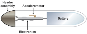
Fig. 9.6 Schematic comparison of how signals are processed in a piezoelectric crystal sensor vs. accelerometer-based sensor. The piezoelectric crystal will count any signal that crosses a given threshold. The accelerometer sensor integrates the voltages of the signals that come from the sensor element.
The ability to respond to anterior/posterior motion allows accelerometer-based systems to respond more appropriately to specific activities, such as cycling. For example, the typical cyclist may not generate much vibratory sensation above the trunk level, which could result in a rate-adaptive pacemaker that incorporates a piezoelectric crystal having a limited response during the activity. Another advantage of the accelerometer is improved specificity of sensor response, i.e., it results in fewer inappropriate responses. For example, a vibration sensor will usually result in a greater rate increase when walking down stairs than walking up stairs because more vibration is generated walking down a flight of stairs.
Rhythmic body motion such as that produced by walking or bicycle riding is typically in the range of 1–8 Hz. Non-exercise-related vibrations that arise from such sources as riding in a car or from nonspecific skeletal muscle noise are often >10 Hz. The accelerometer, which limits analysis of signals to the 1–10 Hz range, should be more specific in its response to activity.
There have been other variations of activity sensors but none has had the clinical success of the accelerometer.
Although accelerometers overcome some of the difficulties with piezoelectric crystal sensors, some problems remain. With prolonged duration activity, the amount of acceleration remains constant, but the physiologic demand for a higher heart rate increases. The extent of acceleration may be similar climbing uphill or moving downhill, but with considerably different requirement for increase in heart rate. Strenuous isometric exercise typically results in an increase in sinus rate, but will not be proportionately increased with accelerometer-based rate-adaptive pacing. In addition, neither vibration nor acceleration sensors will respond to non-movement-based exertion such as emotion or fever.
The overall experience with activity sensors has been very positive and even though accelerometer-based activity sensors now dominate the market and have theoretical and real advantages in some patients, the potential superiority of accelerometer-based technology is difficult to substantiate.1
Minute Ventilation Sensors
Minute volume (respiratory rate × tidal volume) has an excellent correlation with metabolic demand. There is a near-linear relationship between minute ventilation and heart rate below approximately 70% of VO2max.2 At higher workloads, minute ventilation increases more rapidly and this has to be taken into account in minute ventilation pacing algorithms to prevent an inappropriately high pacing rate.
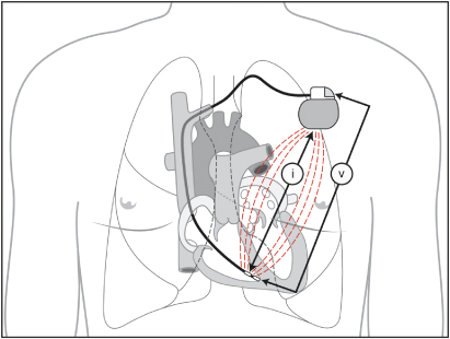
For the purpose of rate-adaptive pacing minute volume measurement is accomplished as follows. Every 50 ms (20 Hz) the device will drive a current waveform between the pacemaker and the ring electrode (320 mA). The device then detects the resulting voltage between the lead tip and indifferent electrode on the header of the can (Fig. 9.7). When both current and voltage are known, transthoracic impedance can be measured between the ring electrode and the pacemaker can. Because transthoracic impedance varies with respiration and its amplitude varies with tidal volume, the impedance measurement can be used to determine respiratory rate and tidal volume, which in turn can be used to alter pacing rate.
Fig. 9.7 The pacemaker sends a current (i) between the ring electrode and the pacemaker can. The sensor detects voltage (v) modulations between the tip electrode and the indifferent electrode on the pacemaker header that occur as a result of changes in transthoracic impedance.
Although the sensor has performed well clinically and the long-term reliability of the minute volume sensor has been excellent, the initial rate response of early minute volume sensors, i.e., at the onset of exercise, compared with an acceleration sensor, was often slower but subsequent generations of the sensor have improved the initial rate response. Inappropriate activation of a minute ventilation sensor is possible with coughing, abnormal breathing patterns, e.g., Cheyne–Stokes breathing, and at times by upper extremity movement. Inappropriate activation of a minute ventilation sensor may also occur when the patient is connected to some electrocardiogram (ECG) monitors that are also capable of documenting ventilatory frequency.3
SonR Sensor (Previously Called Peak Endocardial Acceleration Sensor)
In healthy persons, the autonomic nervous system adjusts cardiac output to meet hemodynamic and metabolic requirements. Even in persons with chronotropic insufficiency, the autonomic nervous system controls the performance of the heart through changes in myocardial contractility.
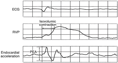
SonR utilizes a microaccelerometer inside a hermetically sealed capsule incorporated in the tip of the pacing lead (Fig. 9.8). The microaccelerometer measures the amplitude of mechanical vibrations that are generated by the myocardium during the isovolumetric contraction phase of the cardiac cycle. The signal obtained is directly related to contractility of the myocardium and peak-to-peak values of the signal are measured, i.e., peak endocardial acceleration (PEA) (Fig. 9.9). An algorithm calculates the pacing rate based on the variation of the peak endocardial signals against a dynamic reference value.4
Fig. 9.8 Peak endocardial acceleration pacing system. The sensor is a microaccelerometer housed inside a rigid, perfectly hermetic capsule within the distal portion of the lead. An associated electronic circuit preprocesses the signal to ensure its correct transmission through the catheter. The rigidity of the capsule allegedly makes the sensor totally insensitive to ventricular pressures and to fibrosis on the lead tip, so that the sensor is sensitive only to the inertial forces generated by myocardial movement.
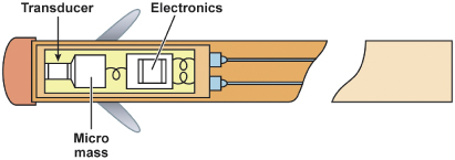
Fig. 9.9 Simultaneous electrocardiogram (ECG), right ventricular pressure (RVP) curve, and peak endocardial acceleration (PEA) waveform. The PEA is represented by the peak-to-peak value of the endocardial acceleration signal measured inside a time window containing the isovolumic contraction phase.
(Reproduced with permission from Sorin Biomedica.)
Multiple studies have shown the sensor to be stable and reliable. In fact, as the lead becomes more fibrosed at the lead–myocardial interface there is even better transmission of myocardial signals, further improving sensor function.
Given the ability to detect early changes in contractility, the sensor has been investigated in patients with malignant vasodepressor syncope. Given the potential ability to react with a change in pacing rate prior to any systemic symptoms from a fall in heart rate or blood pressure (Fig. 9.10), SonR has been shown in small studies to have potential advantages in this group of patients.5,6
Fig. 9.10 Blood pressure (BP), heart rate (HR) and peak endocardial acceleration (PEA) measurements from a patient undergoing tilt testing for presumed neurocardiogenic syncope. The PEA increases dramatically at approximately 11 min. The patient subsequently has typical symptoms accompanied by a decrease in BP and HR approximately 7 min later. Reacting to the earlier increase in PEA has been shown in some patients to prevent or minimize the subsequent vasodepression.
Stay updated, free articles. Join our Telegram channel

Full access? Get Clinical Tree


