Fig. 25.1
Robotic mitral valve replacement—PLA General Hospital Beijing: robotic instruments are inserted into the thorax as shown in this illustration and as described in Chap. 24 (Fig. 24.3). As sutures are withdrawn through the working port, they are organized on individual clamps, assuring each has the correct orientation. The most leftward suture has been passed through the mitral valve annulus at 11 o’clock and withdrawn through the port and organized using a clamp. Progressive left to right sutures correlate to counterclockwise placement of annular sutures and are organized similarly. Thereafter, sutures are passed through the prosthetic valve sewing ring. The valve is then lowered and positioned in the annulus with sutures tied extra-corporeally
At ECU surgeons place the first sutures at the right and left fibrous trigones. Thereafter, sutures are inserted along the anterior annulus. Posterior annular sutures then are placed, beginning at the left trigone and moving counterclockwise toward the posterior annulus. Subsequent suture placement proceeds clockwise from the right trigone posteriorly to completion. Again, we recommend that supra-annular pledgeted sutures for mechanical valve implantation. We use commercial suture guides to maintain meticulous organization to ensure correct needle placement through the valve-sewing ring (Fig. 25.2).
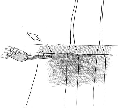
Fig. 25.2
Robotic mitral valve replacement—East Carolina Heart Institute: after instrument trocars (LA left instrument arm, RA right instrument arm, C carbon dioxide catheter) are inserted, we generally pass the camera through the incision working port. Thereafter adhesive Gabbay-Frater™ Suture Guides (SG) (Deknatel-Teleflex, Inc. Limerick, PA) are placed along the lateral chest wall. Here, sutures are organized in separate slots as they are with drawn from the working port
Starting on the left side of the exteriorized sutures, sutures are passed serially through the sewing ring. Figure 25.3 shows the sewing-cuff needle passage technique used at ECU that enables facile suture separation when tying them through a limited incision. After all sutures have been placed around the valve and checked to assure of proper alignment, the valve prosthesis is lowered through the working port (Fig. 25.4). After proper seating, each suture can be tied either with the knot-pushing instrument, shown in Chap. 24 (Scanlan International, Minneapolis, MN), or a similar one.
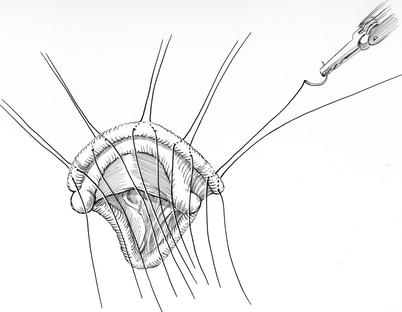
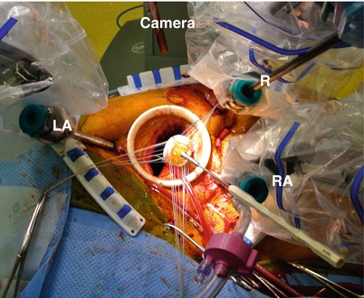
Fig. 25.3
Sewing-ring suture passage technique: suture-bearing needles are passed through the sewing prosthetic valve cuff at an angle, such that they are spaced 1:1 on the cuff bottom with respect to the mitral annulus. By angling needles toward each other when a suture is placed sutures emerge close together on the atrial (top) side. This makes it easier to separate sutures from each other and facilitates tying them
Fig. 25.4


Prosthetic valve insertion: after all sutures have been placed through the valve sewing cuff and checked for accurate placement, the valve holder is removed and the prosthesis is passed through the working port. When using a bioprosthesis, we leave the center template in place as this device “cinches together” the valve struts and prevents suture entrapment. After the three sutures at each strut have been tied, the template is removed and strut position checked. Thereafter, all other sutures are tied. LA left instrument arm, RA right instrument arm, R robotic retractor
Stay updated, free articles. Join our Telegram channel
Full access? Get Clinical Tree
