Previous right thoracotomy
Severe liver dysfunction
Bleeding disorders
Pulmonary hypertension (Fixed PAS >60 Torr)
Significant aortic valve disease
Coronary artery disease requiring surgery
Recent myocardial ischemia (<30 days)
Recent stroke (<30 days)
Severely calcified mitral valve annulus
Patients with poor lung function undergo preoperative pulmonary testing to ascertain whether they will tolerate single lung ventilation. Should patients not be able to tolerate isolation, cardiopulmonary bypass is instituted earlier for pulmonary deflation and intra-thoracic access. In the presence of severe chronic obstructive pulmonary disease, we still prefer to repair patients using a sternotomy. In the presence of severe fixed pulmonary hypertension, especially with an impaired right ventricle, we tend to use a sternotomy so that we can provide optimal myocardial protection.
As we will describe below, the trans-esophageal echocardiogram remains the gold standard for perioperative mitral surgery planning. It is important to correlate the dynamic echocardiographic anatomy and the intra-operative pathology using the Carpentier functional classification. In patients over 40 years old, and/or with a strong family history and/or symptoms of coronary disease, coronary angiography is recommended; although we often use computed tomographic angiography as a screening test.
In the past only symptomatic patients with 3+ or 4+ mitral regurgitation and ruptured/elongated posterior leaflet chords were referred for surgery. With the advent of safe, effective minimally invasive and robotic mitral operations, more asymptomatic patients with moderate to severe regurgitation are being referred earlier. This is especially true for patients who have begun to develop even mild left ventricular dysfunction (EF = 0.50) or dilatation. Moreover, the presence of early atrial fibrillation indicates that significant detrimental changes are in progress. In order to improve long-term survival, there is clear evidence that patients with ruptured chords and a flail leaflet segment should be repaired in that long-term survival may be compromised. Patients with significant regurgitant mitral valves, who are either asymptomatic or in class 1 or 2 heart failure, have a better a long-term survival than those repaired after more advanced failure ensues.
Intra-operative Trans-esophageal Echocardiographic Planning
We believe that three-dimensional (3-D) trans-esophageal (TEE) echocardiography is essential to plan both the simple and complex robotic mitral repairs. Although these operations can be done without this capability, the best pathologic valve definition is determined by a complete 3-D echo study, which also can provide reconstructive modeling. For topographic and dynamic nomenclature, we use Carpentier’s functional mitral insufficiency classification, which is based on leaflet motion characteristics: normal leaflet motion = Type 1, exaggerated (prolapse) leaflet motion = Type 2, and restricted leaflet motion = Type 3. Type 1 and 2 pathologies most commonly lend themselves to robotic mitral repairs, although ischemia related restriction (Type 3b) could be amenable to correction using these methods. As mentioned earlier, Type 3a rheumatic restriction is more difficult to treat using repair techniques.
Chapter 4 in this book details our methods for obtaining and reconstructing 3-D TEE images, which are acquired in the operating room just prior to beginning the repair operation. Briefly, we echo measure all leaflet segments (P1-P3, A1-A3) with particular attention to the length of A2 as well as the height (annulus to coapting edge) of posterior leaflet segments. Next, the direction of each jet (leak) is mapped with both 2-D and 3-D studies. We have been able to define the exact direction and size of each regurgitant jet with 3-D TEE. Next, mobility and level of prolapse is determined for each Type II regurgitant lesions. Any regions of leaflet restriction are determined, and finally, commissural coaptation points with any associated leaks are defined.
We measure the planar angle between the aortic and mitral valve. If this angle is more acute than 120° then there is a greater chance of systolic anterior motion of the anterior leaflet (SAM) after the repair. This is especially true either with high (>2-cm) posterior leaflet segments (particularly at P1 and P2) or in the presence of an anterior leaflet A2 segment length that is greater than 3-cm. Finally, the annular diameter, septal thickness at the outflow tract, and coaptation point to septal (C Sept) distances are measured. Either individually or collectively these measurements can influence the level of anterior leaflet to septal approximation during systole. When possible papillary muscle and chordal anatomy are defined in relation to ventricular size and cardiac contractility. Lastly, any annular or leaflet calcium should be determined, even though this problem can be elusive even with the best echo techniques and technologies.
After the above data have been acquired, a 3-D valve model is constructed from digital measurements. This static model can be imported directly to the da Vinci™ operating console via a program called TilePro™, providing surgeon visualization during the valve reconstruction. Any dynamic echocardiographic or angiographic images can be imported in the same way for the surgeon’s real-time review during the operation. It is our wish to continue to develop advanced real-time 3-D echocardiographic modalities that will enable more surgeons to perform complex mitral valve repairs with more engineering accuracy. Our experience of comparing echocardiographic, direct linear, and band sizer measurements of A2 has shown an excellent correlation between all three lengths. From these data we have developed nomogram for annuloplasty band sizing (Table 24.2). In most cases these correlations have allowed us to rely on TEE measurements alone to select the best band size for implantation.
Table 24.2
Echo-based annuloplasty banda sizing
Anterior leaflet (A2) length | Band size |
|---|---|
20-mm or < | #28 |
22-mm | #30 |
24-mm | #32 |
26-mm | #34 |
28-mm | #36 |
30-mm or > | #38 |
The daVinci ™ Robotic Surgical System
Robotic systems consist of tele-manipulators with end effectors, or micro-instruments, that are controlled remotely from a surgeon’s operating console. Currently, the da Vinci ™ surgical system is the only robotic system approved and available for to perform intra-cardiac surgical procedures. The latest version is the da Vinci™ SI HD (high-definition) surgical system, which was commercialized first in 2009. This system is comprised of an operating console, an electronic vision cart, and a surgical instrument cart. Figure 24.1 shows the overall operating room arrangement with end effector instruments used in robotic mitral valve surgery. For mitral repair surgery the instrument cart should be positioned (Fig. 24.2) along the left side of the patient with the overarching instrument arms entering the right chest. Individual instrument trocars and arms are inserted through specific intercostal spaces as shown in Figs. 24.3 and 24.4. After the two instrument arms, the 3-D camera, and the dynamic retractor have been inserted, the surgeon works from two hand driven robotic sensors that transmit digital instructions to the end effectors of each instrument (Fig. 24.5). A clutching mechanism enables constant re-adjustment of surgeon hand-positions to maintain an optimal ergonomic attitude with respect to the visual field.
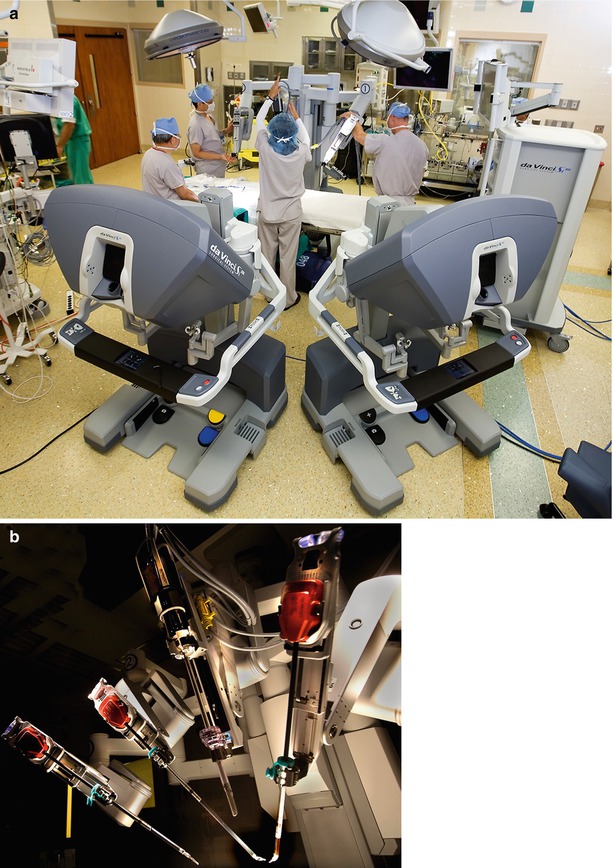
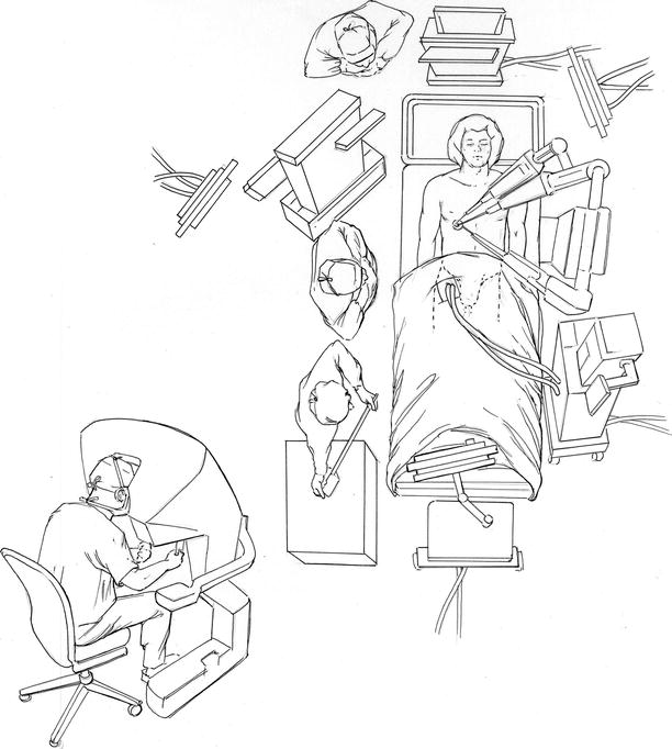
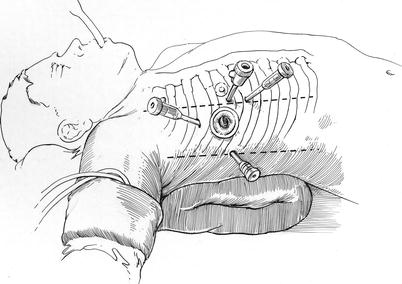
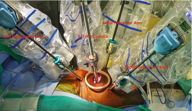
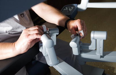
Fig. 24.1
(a) Robotic operating room and instrument cart: the operating room for robotic mitral valve surgery is generally arranged in this fashion. The instrument cart is positioned along the left side of the operating table. The vision cart is placed at the foot of the table, and two surgeons operating consoles are shown. (b) The instrument cart is comprised of three instrument arms with end effector tips. One of these arms is reserved for the dynamic intra-atrial retractor. The high-definition 3-D camera arm is also shown
Fig. 24.2
Operating room set-up: this illustration shows the exact position of the instrument cart, vision cart, and operative console during robotic mitral valve surgery. Moreover, the locations of the anesthesia and echocardiographic teams as well as cardiopulmonary bypass pump are shown
Fig. 24.3
Placement of robotic instrument trocars: robotic instrument and camera trocars are shown: instrument arms are inserted through trocars placed in the 3d (left arm) and fifth (right arm) intercostal spaces (ICS). The camera port is inserted through either an anterior fourth ICS trocar or the 4-cm fourth ICS working port (mini-thoracotomy), which is more lateral and in the same ICS. The dynamic retractor is placed through a sub-mammary fifth ICS trocar inserted in the mid-clavicular line
Fig. 24.4
Robotic instrument deployment: this illustration shows the instrument arms inserted through the trans-thoracic trocars and ready to begin the mitral valve operation. The left and right instruments arms as well as 3-D high definition camera and atrial retractor are engaged. A soft tissue retractor placed in the working-port obviates then need for rib spreading. Carbon dioxide (CO2) is insuflated into the thoracic cavity via the right instrument arm side port
Fig. 24.5
Robotic hand controls: the operating (console) surgeon uses these two micro-switched hand controls to affect ergonomic orientation and deployment of the end effector instrument tips. The action of instrument tips either can be scaled with relationship to hand motions or used real-time 1:1. Moreover, a clutching mechanism allows the surgeon to reorient the hands intermittently to the most comfortable position. During hand re-orientation the instrument tips remain static and only become reactivated upon releasing the clutch. This action maintains both the surgeon’s hands and instrument tips in the best orientation in relation to a variable operative topography
In addition, this system offers a dual-console capability (Fig. 24.6), which enables surgeon training and the potential for collaboration during complex cases. In addition, the robotic EndoWrist ™ instruments have seven degrees of ergonomic freedom, which allow surgeons ideal dexterity using both dominant and non-dominant hands (Fig. 24.7). The wrist-like articulations at the ends of micro-instruments bring the pivoting action into the plane of the operative field, improving dexterity in tight spaces and allowing truly ambidextrous suture placement. The dynamic left atrial retractor provides ideal exposure of the mitral valve and is very easy to reposition (Fig. 24.8). This ability is absolutely necessary to allow full intra-atrial access and exposure for both mitral valve surgery and concomitant MAZE procedures for atrial fibrillation.
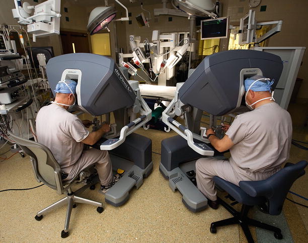
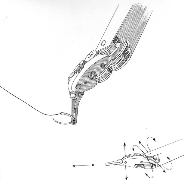
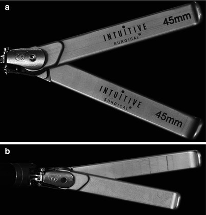
Fig. 24.6
Dual operating consoles: The daVinci SI™ system has the capability to have two operating consoles tethered together, allowing either an assistant surgeon to work with a primary operator or use of the auxiliary console for teaching. When two surgeons are working together, instrument controls can be exchanged back and forth. Moreover, the non-operating console has dynamic pointers that are helpful for teaching. Lastly, using Tile-Pro™ software, diagnostic images and hemodynamic data can be transmitted into the visual field of each console
Fig. 24.7
Robotic instrument “wrist”: the intrinsic elegance of the daVinci™ instruments relates to the ability to perform motion with six degrees of freedom (DOF), which is defined as the freedom of rigid body movement in three-dimensional space. The instrument arm and wristed end effectors are able to move forward/backward, up/down, and left/right in combination with rotation about three perpendicular axes, or pitch, yaw, and roll
Fig. 24.8
(a, b) Dynamic robotic atrial retractor: this device greatly facilitates both mitral and tricuspid valve surgery as well as cryo-maze ablations for atrial fibrillation. The retractor blades can be spread and rotated inside the right or left atrium to provide ideal valve exposure
Anesthesia and Cardiopulmonary Perfusion
Chapters 3 and 5 describe in detail anesthetic management, cardiopulmonary perfusion, and myocardial protection for robotic mitral operations. This chapter will only briefly reiterate these techniques. With the patient in the supine position, either a double lumen endotracheal tube or bronchial blocker is inserted. Then, the 3-D trans-esophageal echocardiographic probe is positioned and the studies described earlier are completed. For hemodynamic monitoring, a thermo-dilution Swan–Ganz™ pulmonary artery catheter (Edwards Lifesciences, Irvine, Calif) is placed via either the subclavian or right internal jugular vein. All intra-vascular cannulations for cardiopulmonary perfusion are done under TEE guidance using the Seldinger guide-wire technique.
While the right neck and shoulder regions are draped for the above instrumentation, our anesthesiologists pass a thin-walled (15-Fr or 17-Fr) Bio-Medicus™ cannula (Medtronic, Minneapolis, MN) via the right internal jugular vein (double-puncture method) into the distal superior vena cava. Thereafter, the patient is placed in a 30° right chest elevated position, prepared, and draped for the operation. Thereafter, the right femoral artery is cannulated using either a 17 or 19-Fr Bio-Medicus™ cannula. For inferior vena caval drainage either 23 or 25-Fr RAP™ femoral venous cannula (Estech, San Ramon, CA) is then passed over a guide-wire into the right atrium. Vacuum-assisted venous drainage is used in all of these operations. Following the left atriotomy and mitral valve exposure, a weighted sucker is placed in the left superior pulmonary vein to scavenge any remaining intra-atrial blood. Carbon dioxide is insufflated continuously through the right robotic arm side-port. At the end of the operation the left atrium is closed by the console surgeon, using running 4-0 PTFE suture, and the heart is de-aired by inflow filling, while ventilating the lungs and applying suction to the aortic root vent.
To monitor adequate limb perfusion during cardiopulmonary bypass, oxygen saturation levels are measured in each leg using the Invos™ System (Somanetics Inc., Troy, MI) When a significant drop in arterial saturation levels occurs in the cannulated leg, we place a wire-directed 5-Fr catheter rapidly into the distal femoral artery and connect it to the arterial perfusion circuit. This generally returns arterial blood saturations toward that of the uninvolved leg. By using this perfusion rescue method for our robotic cases, we have had no ischemia related complications.
Aortic Occlusion and Myocardial Protection
Chapter 5 details techniques for both endo-balloon and trans-thoracic cross-clamp aortic occlusion. We prefer the latter method as it has been proven to be safe, reliable, economic, and simple to apply. For myocardial protection we use a systemic blood inflow temperature of 28 °C with cold aortic root cardioplegia. We place the cardioplegia catheter either via endoscopic or direct vision. In our early cases we used intermittent cold blood cardioplegia. Most recently we have used crystalloid Bretschneider’s HTK solution as the cross clamp times can be extended between infusions. Also, this method helps to reduce the chance of introducing aortic root air, which can occur with multiple infusions. We have used retrograde cardioplegia rarely as the majority of non-rheumatic mitral valve patients have a competent aortic valve and non-flow limiting coronary arteries. When infusing cardioplegia, the dynamic retractor should be lowered to avoid aortic valvular incompetence and assure the best myocardial protection.
Robotic Mitral Valve Repair Toolbox
Instruments
It is very important to select the appropriate instrument for each specific robotic repair task. We generally use only four specialty instruments to perform the actual robotic mitral repair (Fig. 24.9). To grasp thickened myxomatous leaflet tissue, we prefer Resano (8-mm) Endowrist ™ forceps rather than Debakey tipped instruments. The former forceps distribute the grasping force over a larger leaflet area and have smooth teeth that are spaced widely. One should never handle either leaflet or atrial tissue with needle holders as the crushing power will tear and destroy them. Figure 24.10 shows the instrument that we use to shape and apply the cryoprobe when performing concomitant robotic CryoMaze ablations to treat atrial fibrillation. The rounded opening between the tips fit snuggly around the probe, allowing the operator to maintain excellent contact with atrial tissue.
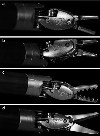

Fig. 24.9
(a–d) Robotic instrument tips (end effectors): these are the main robotic instruments used for mitral valve surgery. (a) Large needle holders. (b) Suture-cut™ Needle holders. (c) Resano tissue forceps. (d) Curved scissors
Fig. 24.10
Robotic probe forceps: these specially designed forceps are used in cryo-maze atrial fibrillation ablations. The tips have a rounded center that is used to mold and apply the round cryoprobe to atrial tissue. Moreover, the tips have atraumatic teeth that can be used to manipulate atrial wall safely when applying the probe
Most sutures are placed using large SutureCut™ Endowrist™ needle drivers. These needle drivers have great gripping power, especially when angling the needles. In this latter circumstance the force vector is altered to put maximum torque on the needle holder. By placing angled needles, where there is maximal needle driver surface contact, one can pass them easily through tough tissue and soft calcium easily. This needle-driver configuration minimizes inadvertent rotation when placing each suture. The SutureCut™ needle holders have a cutting surface along the posterior portion of the instrument. This has been a great advantage in robotic mitral valve surgery, as the console surgeon does not have to rely on the patient-side assistant to cut sutures. This instrument should be used for interrupted sutures; however, when selecting a running suture line, we prefer to switch to the (non-cutting) large need driver. This instrument exchange avoids inadvertent cutting of the running suture. Because of the intrinsic strong gripping strength, large needle drivers are used to remove annular calcium.
Stay updated, free articles. Join our Telegram channel

Full access? Get Clinical Tree


