4 Right-Sided Valvular Disease
Background
Tricuspid Valve Structure and Function
• There is great variability in leaflet and commissural morphology, chordal, and papillary muscle support.
• The anterior papillary muscle is the largest and arises from the moderator band in the right ventricle (RV).
• The tricuspid annulus is apically displaced relative to the mitral valve. It is supported medially by the right fibrous trigone and is thinner posteriorly and laterally.
• Tricuspid annular plane systolic excursion (TAPSE) toward the RV apex is reflective of right ventricular (RV) systolic function (normal 23 mm, range 15-31 mm).
Pulmonic Valve Structure and Function
• The pulmonic valve (PV) is similar to the aortic valve in its semilunar structure and area (normal area 2-4 cm2), with lunula, nodulus of Arantii, and associated sinuses of Valsalva and sinotubular junction.
• Typically, the PV has thinner leaflets, which are termed anterior, left posterior, and right posterior.
Overview of Echocardiographic Approach
• Right-sided valvular assessment uses a similar echocardiographic approach to that used for assessment of the mitral and aortic valves.
• The most efficient examination strategy begins with 2D imaging (structure), followed by CF Doppler mapping (flow, function), followed by PW or CW Doppler (quantitation).
• 3D data sets (including color flow) are easily acquired in real time, but best manipulated after examination or off-line.
• Compared with left-sided valvular assessment, imaging may be more difficult owing to more anterior (far-field) location of right-sided valves and acoustic shadowing from calcified or prosthetic aortic and mitral valves (Box 4-1).
Anatomic Imaging
Standard Scan Planes for Tricuspid and Pulmonic Valves
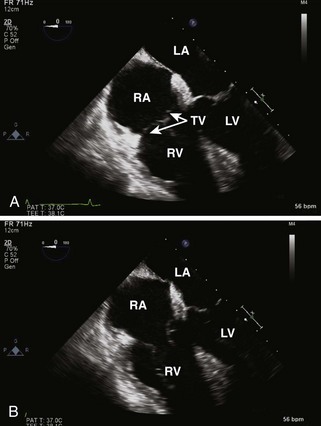
• Midesophageal (ME) four-chamber view allows assessment of TV and RA, RV, IAS, IVS, and adjacent left heart structures (Figure 4-1).
• The TV septal leaflet is seen medially, with either the anterior or the posterior leaflet seen laterally.
• Transesophageal echocardiography (TEE) probe insertion, which brings the coronary sinus into view, most likely displays the posterior TV leaflet.
• TEE probe withdrawal, which brings the RA appendage into view, most likely displays the anterior TV leaflet.
• The tricuspid annular dimension can be measured in this view (normal 28 mm, range 20-40 mm). TAFS and TAPSE can be measured to assess RV function.
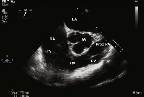
• ME RV inflow-outflow view displays RA, TV, RV, PV, and PA, all “wrapping around” a centered aortic valve, seen in short axis (Figure 4-2).
• The TV anterior leaflet appears medially and the TV posterior leaflet appears laterally, but there is some variability to this typical pattern.
• The PV leaflets are seen between the RV and the proximal PA, generally in long axis, in the far right portion of the video display. The leaflets are often not distinctly seen.
• CF Doppler allows assessment of a TR jet in the RA or a pulmonic regurgitation (PR) jet in the RV.
• Spectral Doppler assessment of a TR jet is often better in this view, owing to a more parallel alignment with the ultrasound beam.
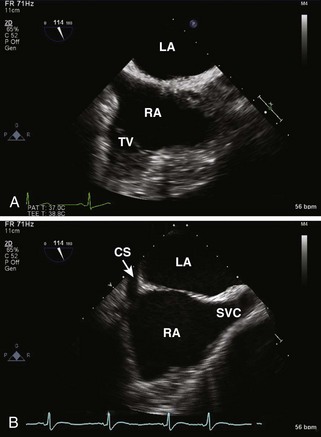
• Modified ME bicaval view displays the TV in addition to the RA, LA, IAS, SVC, and coronary sinus (Figure 4-3).
• This view is seen with slight counterclockwise probe rotation and a TEE probe angle greater than that needed for the bicaval view (typically 100-140 degrees).
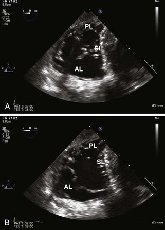
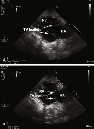
• Transgastric (TG) RV Midpapillary short axis view is acquired with counterclockwise probe rotation beginning with a transgastric LV midpapillary short axis view. It often demonstrates the leaflets of the TV when the TEE probe is withdrawn or anteflexed slightly (Figure 4-4).
• TG RV inflow view displays the TV in long axis as well as portions of the RA and the RV (Figure 4-5).
• This view is usually obtained with the probe turned slightly to the patient’s right (clockwise) and a probe angle of 90 to 110 degrees.
• The inferior free wall appears in the near field of the display and the anterior free wall is seen in the far field.
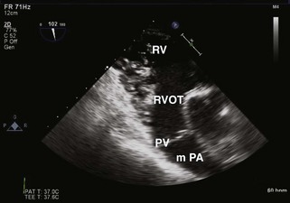
• TG RV outflow view displays the PV in long axis, with the TV, RV, RA, LA, and proximal PA in other orientations (Figure 4-6).
• This view is acquired by slight counterclockwise probe rotation and using a probe angle of 130 to 145 degrees.
• The right ventricular outflow tract (RVOT) and PV appear in the mid-far field, usually parallel to the ultrasound beam.
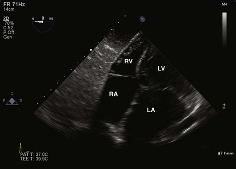
• Deep TG four-chamber view displays the RV and the other three cardiac chambers, much like the ME four-chamber view (Figure 4-7).
• Beginning with a deep TG four-chamber view, clockwise probe rotation will often show the RV, RA, and TV in the center of the image display.
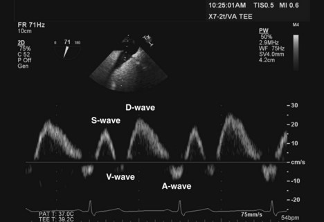
• TG HV view can be acquired from a TG probe location and allows measurement of HV flow velocity with PW Doppler, which is useful for TR quantification (Figure 4-8).
• Often best imaged from the RV short axis views by turning the probe to the right (clockwise), identifying an HV, and adjusting the multiplane angle to optimally align the direction of flow with the ultrasound beam.
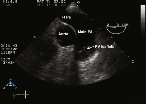
• ME ascending aortic short axis view is acquired with slight TEE probe withdrawal (Figure 4-9).
• This view displays the proximal ascending aorta in short axis, the adjacent proximal PA, its bifurcation, and the right PA.
• Alignment is ideal for spectral Doppler analysis of proximal PA flow or PV flow, especially when the valve is seen clearly.
• Upper esophageal (UE) aortic arch short axis view allows visualization of the PV in long axis as well as a significant portion of the main PA (Figure 4-10).
• This view of the PV may be improved by turning the probe slightly to the left (counterclockwise) and retroflexing the tip.
