Chapter 4 Respiratory system resistance
 Gas flow in the airway is a mixture of laminar and turbulent flow, becoming more laminar in smaller airways.


Elastic resistance, which occurs when no gas is flowing, results from only two of the numerous causes of impedance to inflation of the lung (listed in the previous chapter). This chapter considers the remaining components, which together are referred to as non-elastic resistance or respiratory system resistance. Most non-elastic resistance is provided by frictional resistance to airflow and thoracic tissue deformation (both lung and chest wall), with small contributions from the inertia of gas and tissue, and compression of intrathoracic gas.1 Unlike elastic resistance, work performed against non-elastic resistance is not stored as potential energy (and therefore recoverable), but is lost and dissipated as heat.
Physical Principles of Gas Flow and Resistance
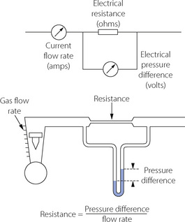
Gas flows from a region of high pressure to one of lower pressure. The rate at which it does so is a function of the pressure difference and the resistance to gas flow, thus being analogous to the flow of an electrical current (Figure 4.1). The precise relationship between pressure difference and flow rate depends on the nature of the flow which may be laminar, turbulent or a mixture of the two. It is useful to consider laminar and turbulent flow as two separate entities but mixed patterns of flow usually occur in the respiratory tract. With a number of important caveats, similar basic considerations apply to the flow of liquids through tubes, which is considered in Chapter 7.
Laminar Flow
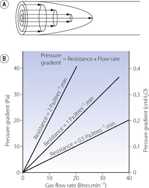
With laminar flow, gas flows along a straight unbranched tube as a series of concentric cylinders that slide over one another, with the peripheral cylinder stationary and the central cylinder moving fastest, the advancing cone forming a parabola (Figure 4.2A).
The advancing cone front means that some fresh gas will reach the end of a tube while the volume entering the tube is still less than the volume of the tube. In the context of the respiratory tract, this is to say that there may be significant alveolar ventilation when the tidal volume is less than the volume of the airways (the anatomical dead space), a fact that is very relevant to high frequency ventilation (page 473). For the same reason, laminar flow is relatively inefficient for purging the contents of a tube.
Quantitative relationships. With laminar flow the gas flow rate is directly proportional to the pressure gradient along the tube (Figure 4.2B), the constant being thus defined as resistance to gas flow:

In a straight unbranched tube, the Hagen–Poiseuille equation allows gas flow to be quantified:
By combining these two equations:
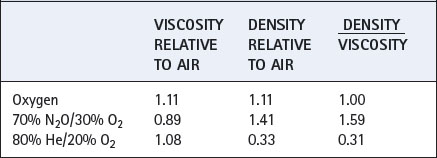
In this equation the fourth power of the radius of the tube explains the critical importance of narrowing of air passages. With constant tube dimensions, viscosity is the only property of a gas that is relevant under conditions of laminar flow. Helium has a low density but a viscosity close to that of air and will not therefore improve gas flow if the flow is laminar (page 46).
In the Hagen–Poiseuille equation, the units must be coherent. In CGS units, dyn.cm−2 (pressure), ml.s−1 (flow) and cm (length and radius) are compatible with the unit of poise for viscosity (dyn.sec.cm−2). In SI units, with pressure in kilopascals, the unit of viscosity is newton second.metre−2 (see Appendix A). However, in practice it is still customary to express gas pressure in cmH2O and flow in l.s−1. Resistance therefore continues to usually be expressed as cmH2O per litre per second (cmH2O.l−1.s).
Turbulent Flow
High flow rates, particularly through branched or irregular tubes, result in a breakdown of the orderly flow of gas described above. An irregular movement is superimposed on the general progression along the tube (Figure 4.3A), with a square front replacing the cone front of laminar flow. Turbulent flow is almost invariably present when high resistance to gas flow is a problem.
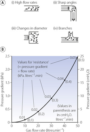
The square law relating driving pressure and flow rate is shown in Figure 4.3B. Resistance, defined as pressure gradient divided by flow rate, is not constant as in laminar flow but increases in proportion to the flow rate. Units such as cmH2O.l−1.s should therefore be used only when flow is entirely laminar. The following methods of quantification of ‘resistance’ should be used when flow is totally or partially turbulent.

k1 contains the factors of the Hagen–Poiseuille equation and represents the laminar flow component while k2 includes factors in the corresponding equation for turbulent flow. Mead & Agostoni2 summarised studies of normal human subjects in the following equation:


Reynolds’ Number
The property of the gas that affects Reynolds’ number is the ratio of density to viscosity. When Reynolds’ number is less than 2000, flow is predominantly laminar, whereas above a value of 4000, flow is mainly turbulent.3 Between these values, both types of flow coexist. Reynolds’ number also affects the entrance length, that is the distance required for laminar flow to become established, which is derived from:
Values for some gas mixtures that a patient may inhale are shown relative to air in Table 4.1. Viscosities of respirable gases do not differ greatly but there may be very large differences in density.
Respiratory System Resistance
Airway Resistance
This results from frictional resistance in the airways. In the healthy subject, the small airways make only a small contribution to total airway resistance because their aggregate cross-sectional area increases to very large values after about the eighth generation (see Figure 2.4). Overall airway resistance is therefore dominated by the resistance of the larger airways.
Gas flow along pulmonary airways is very complex when compared to the theoretical tubes described above, and consists of a varying mixture of both laminar and turbulent flow. Both the velocity of gas flow and airway diameter (and therefore Reynolds’ number) decrease in successive airway generations from a maximum in the trachea to almost zero at the start of the pulmonary acinus (generation 15). In addition, there are frequent divisions with variable lengths of approximately straight airway between. Finally, in large diameter airways entrance length is normally greater than the length of the individual airway. As a result of these purely physical factors laminar flow cannot become established until approximately the 11th airway generation. Predominantly turbulent flow in the conducting airways has two practical implications. First, the physical characteristics of the airway lining will influence frictional resistance more with turbulent than with laminar flow, so changes in airway lining fluid consistency (page 218) will have a significant effect. Second, gas mixtures containing helium (low Reynolds’ number) are more beneficial in overcoming increased resistance in large airways and of less benefit in small airway disease such as asthma.
Tissue Resistance
In 1955 Mount identified a component of the work of breathing which he attributed to the resistance caused by tissue deformation.4 D’Angelo et al5 subsequently described how, in anaesthetised and paralysed subjects, the viscoelastic ‘tissue’ component of respiratory resistance may be measured.
Figure 4.4 shows the ‘spring and dashpot’ model, which D’Angelo et al5 used to illustrate this component of respiratory resistance. Dashpots here represent resistance, and springs elastance (reciprocal of compliance). Upward movement of the upper bar represents an increase in lung volume, caused by contraction of the inspiratory muscles or the application of inflation pressure as shown in the diagram. There is good evidence that, in humans, the left hand dashpot represents predominantly airway resistance. The spring in the middle represents the static elastance of the respiratory system. On the right there is a spring and dashpot arranged in series. With a rapid change in lung volume, the spring is extended while the piston is more slowly rising in the dashpot. In due course (approx 2–3 seconds) the spring returns to its original length and so ceases to exert any influence on pressure/volume relationships. This spring therefore represents the time dependent element of elastance. While it is still under tension at end-inspiration, the combined effect of the two springs results in a high elastance of which the reciprocal is the dynamic compliance. If inflation is held for a few seconds and movement of the piston through the right hand dashpot is completed, the right hand spring ceases to exert any tension and the total elastance is reduced to that caused by the spring in the middle. The reciprocal of this elastance is the static compliance, which is therefore greater than the dynamic compliance. D’Angelo et al5 stress that the system shown in Figure 4.4 is only a simplified scheme to which many further components could be added; nevertheless the model accords well with experimental findings.
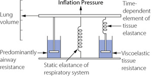
Fig. 4.4 The spring and dashpot model of D’Angelo et al.5 Inflation of the lungs is represented by the bar moving upwards. The springs represent elastance (reciprocal of compliance) and the dashpots resistance. The spring and dashpot in series on the right confers time dependence which is due to viscoelastic tissue resistance.
The time dependent change in compliance represented by the spring and dashpot in series could be due to many factors. Redistribution of gas makes only a negligible contribution in normal man, the major component being due to viscoelastic flow resistance in tissue.1,5 In anaesthetised healthy subjects tissue resistance is of the order of half of the respiratory system resistance,5 and seems to be largely unaffected by end-expiratory pressure or tidal volume.6 Tissue resistance originates from both lung and chest wall tissues with a significant proportion originating in the chest wall.6,7,8 The magnitude and importance of this component, particularly in lung disease, has often been underestimated and it is clearly important to distinguish airway resistance from that afforded by the total respiratory system. Separate measurement of tissue resistance is described below.
Inertance as a Component of Respiratory System Resistance
Respired gases, the lungs and the thoracic cage all have appreciable mass and therefore inertia, which must offer an impedance to change in direction of gas flow, analogous to electrical inductance. This component, termed inertance, is extremely difficult to measure, but inductance and inertance offer an impedance that increases with frequency. Therefore, although inertance is generally believed to benegligible at normal respiratory frequencies, it may become appreciable during high frequency ventilation (Chapter 32).
Factors Affecting Respiratory Resistance
In normal lungs respiratory resistance is controlled by changes in airway diameter mainly in small airways and bronchioles. This would be expected to alter only the airway component of respiratory resistance but animal studies suggest that contraction of bronchial smooth muscle also causes changes in tissue resistance. It is thought that airway constriction distorts the surrounding tissue sufficiently to alter its viscoelastic properties.9 Airway calibre may be reduced by either physical compression (due to a reversal of the normal transluminal pressure leading to airway collapse) or by contraction of the smooth muscle in the airway wall.
Volume-Related Airway Collapse
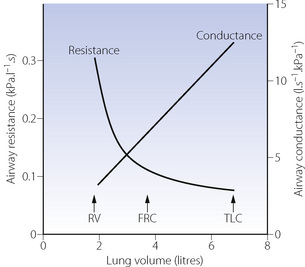
Effect of lung volume on resistance to breathing. Whenthe lung volume is reduced, there is a proportional reduction in the volume of all air-containing components, including the air passages. Thus, if other factors (such as bronchomotor tone) remain constant, airway resistance is an inverse function of lung volume (Figure 4.5) and there is a direct relationship between lung volume and the maximum expiratory flow rate that can be attained (see below). Quantifying airway diameter is difficult from these curves. It is therefore more convenient to refer to conductance, which is the reciprocal of resistance and usually expressed as litres per second per cmH2O. Specific airway conductance (sGaw) is the airway conductance relative to lung volume or the gradient of the line showing conductance as a function of lung volume (Figure 4.5). Because it takes into account the important effect of lung volume on airway resistance, it is a useful index of bronchomotor tone.
Gas trapping. At low lung volumes, flow-related airway collapse (see below) occurs more readily because airway calibre and the transmural pressure are less. Expiratory airway collapse gives rise to a ‘valve’ effect and gas becomes trapped distal to the collapsed airway, leading to an increase in residual volume and FRC. Thus, in general, increasing lung volume reduces airway resistance and helps to prevent gas trapping. This is most conveniently achieved by the application of continuous positive airway pressure (CPAP) to the spontaneously breathing subject or positive end-expiratory pressure (PEEP) to the paralysed ventilated patient (Chapter 32
Stay updated, free articles. Join our Telegram channel

Full access? Get Clinical Tree


