Chapter 32 Respiratory support and artificial ventilation
 Non-invasive ventilation may be used to increase airway pressure and support a failing respiratory system without the need for tracheal intubation or tracheostomy.


Non-Invasive Ventilation1,2
Negative Pressure Ventilation3
This requires the application of subatmospheric pressure to the trunk. It was first reported in 19294 and widely used for the following 30 years during polio epidemics. Enthusiasm for the technique has fluctuated since, but there continues to be interest in negative pressure ventilation for a small group of patients.5
Animal studies comparing negative and positive pressure ventilation show that lung perfusion is the same with both modes, but that ventilation is more evenly distributed and oxygenation better with negative pressure ventilation.6 Negative pressure ventilation continues to have a place in the management of respiratory failure due to neuromuscular disorders,3 central apnoeas,1 or in paediatric intensive care.5
Hayek oscillator is a form of cuirass that encircles the trunk and allows high frequency ventilation (see below) with a continuous negative pressure.7 It facilitates a wide range of tidal volumes, and some degree of control of the functional residual capacity (FRC). It may be used during surgery on the airway so avoiding the need for any form of tracheal tube.8
Non-Invasive Positive Pressure Ventilation1,2
Positive pressure ventilation may be delivered using soft masks that fit over the mouth and nose, the nose only, or with a clear plastic helmet over the entire head (sealed around the neck). Most ventilator systems used are pressure generators and so are ‘leak tolerant’; that is, flow automatically increases to compensate for a pressure drop due to gas leakage. With nasal ventilation, positive pressure in the nasopharynx normally displaces the soft palate anteriorly against the tongue, thus preventing escape of gas through the mouth. Adverse effects of nasal ventilation include eye irritation, conjunctivitis and facial skin necrosis. Helmet systems avoid these complications, but have a volume of around 10 litres which inevitably causes some rebreathing making hypercapnia a potential problem. The high volume in the helmet also results in a time delay when changing the pressure in the helmet to support ventilation or when sensing a spontaneous breath with pressure changes (see below).9
Techniques of ventilation are similar to invasive artificial ventilation. Ventilator modes that use patient triggering are better tolerated than controlled ventilation, particularly in awake patients, but both techniques are used. Pressure controlled ventilation or pressure support ventilation (PSV, see below) are commonly used, as is continuous positive airway pressure (CPAP). In bilevel positive airway pressure (bilevel PAP) the ventilator pressure steps between two preset values for inspiration and expiration, and, except for the terminology used to describe the pressures, is the same as PSV with CPAP.1
Ventilation may be provided continually during acute respiratory problems, or only at night for long-term respiratory disease.10 The use of nasal CPAP for treating the sleep apnoea hypopnoea syndrome has been described on page 275. In this case, benefit occurs simply be displacing the soft palate away from the posterior pharyngeal wall. Benefit in other respiratory diseases is more difficult to explain, but possible mechanisms include:2

 delivery of a higher inspired oxygen concentration by the use of a tight fitting facemask (page 206)


Clinical applications.2,11 NIV is now advocated for the treatment of acute respiratory failure from numerous causes, though outcome evidence supporting its use is variable as follows:
 Chronic obstructive pulmonary disease (COPD) exacerbations (page 409). NIV is now first line treatment for this situation, and improves survival, reduces the need for invasive ventilation and reduces the length of hospital stay. The case for long-term treatment of COPD remains controversial, with some benefits in some sub-groups only.12
 Cardiogenic pulmonary oedema may be successfully treated with NIV, reducing the need for tracheal intubation and improving mortality.13 The mechanism of this beneficial effect is explained on page 480.
 Acute lung injury (ALI). NIV instituted early in the course of ALI (Chapter 31) may reduce the need for tracheal intubation and improve gas exchange,14,15 but the evidence for improved survival is currently inconclusive.11
 Failure of weaning from invasive ventilation (page 474). NIV may be used to gradually wean patients from invasive ventilation, a strategy that is particularly useful in patients with COPD16 or obesity.17
Intermittent Positive Pressure Ventilation (IPPV)
Phases of the Respiratory Cycle
Inspiration. During IPPV, the mouth (or airway) pressure is intermittently raised above ambient pressure. The inspired gas then flows into the lungs in accord with the resistance and compliance of the respiratory system. If inspiration is slow, the distribution is governed mainly by regional compliance. If inspiration is fast, there is preferential ventilation of parts of the lungs with short time constants (Figure 3.7). Different temporal patterns of pressure may be applied, as discussed below.
Expiration. During IPPV, expiration results from allowing mouth pressure to fall to ambient. Expiration is then passive, and differs from expiration during spontaneous breathing in which diaphragm muscle tone is gradually reduced (page 63). Expiration may be impeded by the application of PEEP. In the past, expiration was sometimes accelerated by the application of a subatmospheric pressure, termed negative end-expiratory pressure (NEEP), though this technique is no longer used. Expiration to ambient pressure is termed zero end-expiratory pressure (ZEEP).
Time Course of Inflation and Deflation
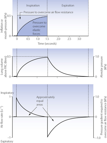
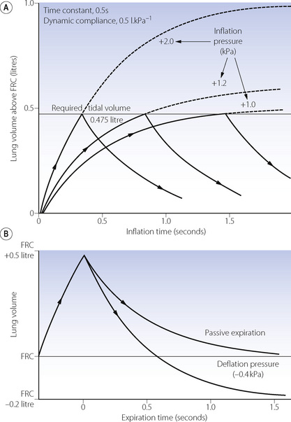
Equilibration according to the above equation usually takes several seconds. When the airway pressure is raised during inspiration, it is opposed by the two forms of impedance – the elastic resistance of lungs and chest wall (Chapter 3) and resistance to air flow (Chapter 4). At any instant, the inflation pressure equals the sum of the pressures required to overcome these two forms of impedance. The pressure required to overcome elastic resistance equals the lung volume above FRC divided by the total (dynamic) compliance, while the pressure required to overcome air flow resistance equals the air flow resistance multiplied by the instantaneous flow rate.
The effect of applying a constant pressure (or square wave inflation) is shown in Figure 32.1. The two components of the inflation pressure vary during the course of inspiration while their sum remains constant. The component overcoming air flow resistance is maximal at first and declines exponentially with air flow as inflation proceeds. The component overcoming elastic resistance increases with the lung volume. With normal respiratory mechanics in the unconscious patient, the change in lung volume should be 95% complete in about 1.5 seconds, as in Figure 32.1.
The approach of the lung volume to its equilibrium value is according to an exponential function of the wash-in type (see Appendix E). The time constant, which is the time required for inflation to 63% of the equilibrium value, equals the product of resistance and compliance. Normal values for an unconscious patient are as follows:


or

The time constant is the time that would be required to reach equilibrium if the initial inspiratory flow rate were maintained. It is sometimes more convenient to use the half-time, which is 0.69 times the time constant. The inflation curve is shown in full with further mathematical detail in Appendix E.
If expiration is passive and mouth pressure remains at ambient, the driving force is the elevation of alveolar pressure above ambient, caused by elastic recoil of lungs and chest wall. This pressure is dissipated in overcoming air flow resistance during expiration. In Figure 32.1, during expiration the alveolar pressure (proportional to the lung volume above FRC) is directly proportional to expiratory flow rate, and all three quantities decline according to a wash-out exponential function with a time constant which is again equal to the product of compliance and resistance.
The Effect of Changes in Inflation Pressure, Resistance and Compliance
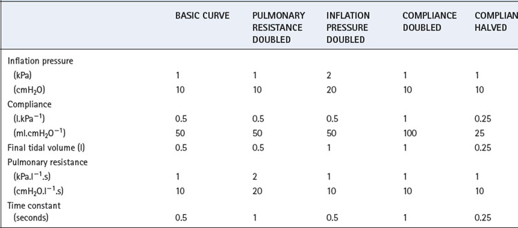
The heavy line in Figure 32.2 shows the inflation curve for the normal parameters of an unconscious paralysed patient as listed in Table 32.1. These are the same values that were considered above. The basic curve is a single exponential approaching a lung volume 0.5 litre above FRC with a time constant of 0.5 seconds.
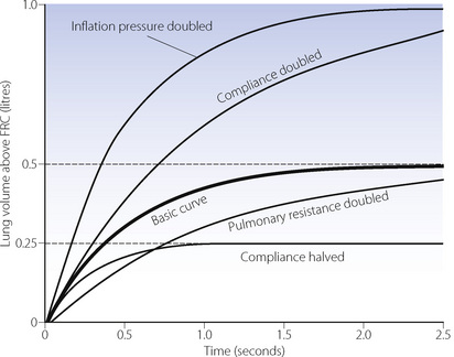
Fig. 32.2 Effect of changes in various factors on the rate of inflation of the lungs. Fixed relationships: final tidal volume achieved = inflation pressure × compliance; time constant = compliance × resistance. (See also Table 32.1.)
Changes in inflation pressure do not alter the time constant of inflation, but directly influence the amount of air introduced into the lungs in a given number of time constants. In Figure 32.2, each point on the curve labelled ‘inflation pressure doubled’ is twice the height of the corresponding point on the basic curve for the same time.
Effect of changes in compliance and resistance. If the compliance is doubled, the equilibrium tidal volume is also doubled. However, the time constant (product of compliance and resistance) is also doubled and therefore the equilibrium volume is approached more slowly (Figure 32.2). Conversely, if the compliance is halved, the equilibrium tidal volume is also halved and so is the time constant.
Changes in resistance have a direct effect on the time constant of inflation but do not affect the equilibrium tidal volume. Thus the effect of an increased resistance on tidal volume is through the reduction in inspiratory flow rate. Within limits, this can be counteracted by prolonging inspiration or by increasing the inflation pressure and the degree of overpressure (explained below). The effects, shown in Figure 32.2, apply not only to the whole lung but also to regions that may have different compliances, resistances and time constants (page 121).
Overpressure. Increasing the inflation pressure has a major effect on the time required to achieve a particular lung volume above FRC. In Figure 32.3, the lung characteristics are the same as for the basic curve in Figure 32.2. If the required tidal volume is 475 ml, this is achieved in 1.5 seconds with an inflation pressure of 10 cmH2O. However, the same lung volume is achieved in only 0.3 seconds by doubling the inflation pressure. The application of a pressure that, if sustained, would give a tidal volume higher than that which is intended, is known as overpressure; it is used extensively to increase the inspiratory flow rate and so to shorten the inspiratory phase. The use of a subatmospheric pressure to increase the rate of passive expiration is similar in principle but is complicated by airway trapping (Figure 32.3B).
Deviations from true exponential character of expiration. It is helpful to assume that the patterns of air flow described above are exponential in character, as this greatly assists our understanding of the situation. However, there are many reasons why air flow should not be strictly exponential in character. Air flow is normally partly turbulent (see Chapter 4) and therefore resistance cannot be considered as a constant. Furthermore, as expiration proceeds, the calibre of the air passages decreases and there is also a transition to more laminar flow as the instantaneous flow rate decreases. Approximation to a single exponential function is nevertheless good enough for many practical purposes.
Alternative Patterns of Application of Inflation Pressure
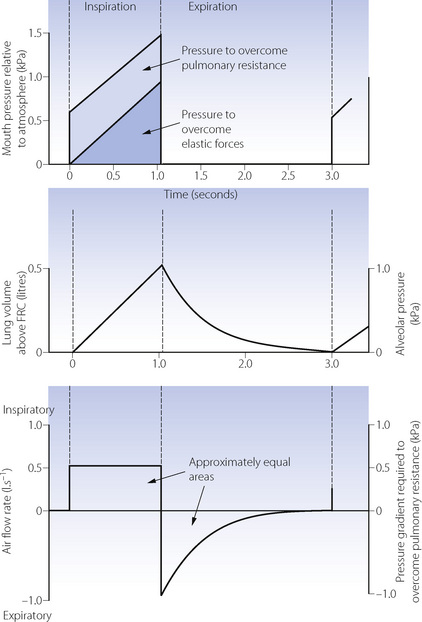
Constant flow rate ventilators are extensively used, and Figure 32.4 shows pressure, volume and flow changes in a manner analogous to Figure 32.1.
Control of Duration of Inspiration
Three methods are in general use.
The Inspiratory to Expiratory (I:E) Ratio
Gas redistribution during an inspiratory hold reduces the dead space (page 130) and so results in a lower Pco2 for the same minute volume. This permits the use of a lower peak inflation pressure.


Clinical Use of IPPV
The previous section classifies ventilators according to the method of gas flow generation – for example, constant flow or constant pressure generators – based on the mechanism by which the ventilator worked. Most ventilators in clinical use in the developed world are now electronically controlled. These allow accurate control of gas pressure and flow throughout the ventilator circuit, and can normally perform as either flow or pressure generators, usually with a variety of inspiratory flow patterns. In addition, they have given rise to a whole host of previously impossible ventilatory techniques, a majority of which are dependent on the ventilator responding appropriately to the patient’s own respiratory efforts.
Interactions Between Patient and Ventilator
For many years there have been ventilators in which the inspiratory phase could be triggered with a spontaneous breath, and mechanical ventilators could be modified to facilitate a mandatory minute volume of ventilation, as described below. Electronic ventilators continuously monitor tidal volume, whether generated by the patient (spontaneous breath) or artificially (ventilator breath). With this information available it is a simple task to achieve, by electronic means, a predetermined minute volume, number of breaths, etc. by introducing extra ventilator breaths when necessary. The challenge for ventilator design in recent years has been the speed and sensitivity with which ventilators can sense, and respond to, the patient’s own respiratory efforts in order to synchronise ventilator and spontaneous breaths. Without this synchronisation, a patient with any reasonable spontaneous respiratory effort begins to ‘fight’ against the ventilator18 leading to discomfort, poor gas exchange and cardiovascular disturbance.
There are two ways by which a ventilator may detect the onset of a spontaneous breath.19
Ventilatory Modes in Common Use
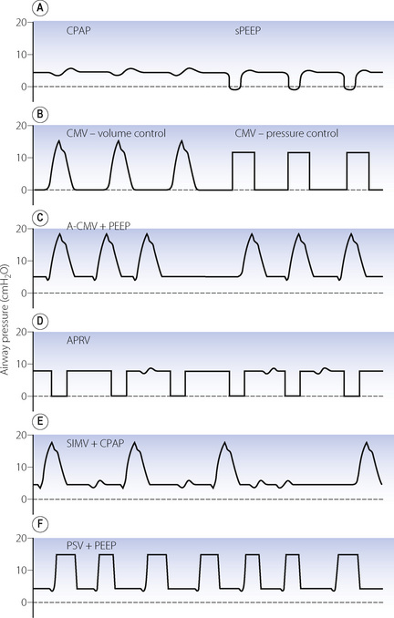
In addition to control mode ventilation (CMV), there are now a range of ventilation patterns. Many of these are essentially the same but have different nomenclature owing to their development by rival ventilator manufacturers. Those in common use are described below and shown graphically in Figure 32.5.
Mandatory minute volume (MMV). Introduced in the 1970s, this was a simple technique for controlling the volume of artificial ventilation so that the total of spontaneous and artificial ventilation did not fall below a preset value. If the patient was able to achieve the preset level of MMV ventilator breaths did not occur. Achievement of the preset MMV by a rapid, shallow respiratory pattern commonly seen in intensive care patients was a major disadvantage of MMV. Electronic ventilators allow MMV to be used, and can co-ordinate the mandatory breaths with patient respiration to a greater degree than the original mechanical technique, including varying both the inspiratory pressure and timing to suit individual patient requirements.20
Assist-control ventilation or synchronised IPPV (Figure 32.5C). This was one of the earlier ventilatory modes that depended on patient triggering of ventilator breaths. It is essentially the same as volume preset IPPV except that breaths are triggered by the patient, normally as a result of reduced circuit pressure. A maximum time delay between breaths is incorporated, following which a breath will be generated by the ventilator if spontaneous triggering has ceased. There is no provision for spontaneous breathing between ventilator breaths.
Airway pressure release ventilation (Figure 32.5D).21 This ventilation mode differs significantly from all other forms of positive pressure ventilation and is essentially the reverse of IPPV. It consists of maintaining the breathing system at an upper airway pressure level (Phigh), which is intermittently released to a lower airway pressure level (Plow), causing the patient to exhale to FRC. The pattern of the imposed breaths is similar to that of reversed I:E ratio. The patient is able to breathe spontaneously throughout the entire respiratory cycle, but most of the time this will be during Phigh when inspiration will start from a lung volume greater than FRC. Artificial breaths are thus within the conventional tidal range set by his FRC, while spontaneous inspirations are usually within his inspiratory reserve. More frequent and longer periods at Plow lead to a greater minute volume, and so improved elimination of carbon dioxide, and a lower mean airway pressure, but are also associated with greater likelihood of pulmonary collapse in injured lungs and, as a consequence, worsening of oxygenation.
Synchronised intermittent mandatory ventilation (SIMV) (Figure 32.5E). Intermittent mandatory ventilation was introduced in the 1970s, followed a few years later by the ability to synchronise ventilator breaths with the patient’s own respiratory effort as described above. The essential feature of SIMV is to allow the patient to take a spontaneous breath between artificial breaths. This confers three major advantages. First, a spontaneous inspiration is not obstructed by a closed inspiratory valve and this helps to prevent the patient fighting the ventilator. The second advantage is the facilitation of weaning, which is considered below. Thirdly, the patient is able to breathe spontaneously at any time during prolonged ventilation; this may prevent respiratory muscle atrophy and helps to reduce the mean intrathoracic pressure. Most ventilators now provide SIMV as a normal feature with either pressure or volume controlled breaths and it is used extensively, often in conjunction with pressure support ventilation (see below).
Pressure support ventilation (PSV) (Figure 32.5F).22 In this system a spontaneous inspiration triggers a rapid flow of gas that increases until airway pressure reaches a preselected level. Flow sensing by the ventilator is also then able to detect when the spontaneous inspiration ends, at which point the pressure support ceases, and expiration occurs. The purpose is not to provide a prescribed tidal volume, but to assist the patient in making an inspiration of a pattern that lies largely within his own control. The level of support may be increased until the pressure is sufficient to provide the full tidal volume (maximal pressure support) and may be gradually reduced as the patient’s ventilatory capacity improves. The amount of pressure support provided does seem to be inversely related to the work of breathing.
High Frequency Ventilation23
High frequency ventilation may be classified into the following three categories:
Stay updated, free articles. Join our Telegram channel

Full access? Get Clinical Tree


