which is a function of the acquisition time  . One acquisition consists of a set of projection images
  with
with  the coordinates of the 2D flat panel for the projection image acquired at time
  .
.
In dynamic tomography, the spatial distribution of tissues changes during the acquisition due to patient movements so the sought CT  is a function of space and time, i.e.,
  with
with  the field-of-view and
  the voxel intensity at point
  and time
  . Assuming a monochromatic beam, no scattering and an ideal flat panel, the relationship between
  and
and  is given by the Beer-Lambert law
with  the intensity of the X-ray source and
  the straight line segment going from the X-ray source to the flat panel pixel with coordinates
  .
.
is a function of space and time, i.e., with the field-of-view and the voxel intensity at point and time . Assuming a monochromatic beam, no scattering and an ideal flat panel, the relationship between and is given by the Beer-Lambert law(14.1)
the intensity of the X-ray source and the straight line segment going from the X-ray source to the flat panel pixel with coordinates .Reconstructing  from an acquisition
  is the inverse problem of tomography. Because the dynamic tomography
  is a 3D+t function and the set of cone-beam projection images
  is a 2D+t function, the reconstruction of
  is only possible based on a model of the breathing motion during the cone-beam acquisition.
from an acquisition is the inverse problem of tomography. Because the dynamic tomography is a 3D+t function and the set of cone-beam projection images is a 2D+t function, the reconstruction of is only possible based on a model of the breathing motion during the cone-beam acquisition.14.2.1 Static Cone-Beam Reconstruction
The simplest solution is to assume that the scanned object is static during acquisition, i.e.,  . The acquisition protocol is then designed to acquire enough projection images for the reconstruction of the 3D cone-beam CT image from the 2D+t sequence. Many solutions have been proposed to the problem of cone-beam CT reconstruction for circular trajectories but none of them is exact since the acquisition does not satisfy Tuy’s data sufficiency condition [57]. So far, the preferred algorithm for circular cone-beam CT has been Feldkamp, Davis and Kress (FDK) algorithm [15], the popularity of which stems from its simplicity and its efficiency. The reader is referred to the extensive literature on the subject for its mathematical description and details on its implementation, e.g., [21]. Briefly, the FDK algorithm is a filtered backprojection algorithm. The filtered projections are obtained with a ramp filter applied to the weighted projection images
 where
where  is a 2D weighting function which depends on the scanner geometry,
  is the unit vector of the flat panel coordinate system orthogonal to the rotation axis of the scanner and
  is the dot product. This formula converts the measured projection values
  to attenuation values using Eq. 14.1, weights the attenuation images with a 2D function
  and applies a ramp filter in the direction
  . The two integrals correspond to the Fourier transform and its inverse in the direction
  . The final solution is obtained with the weighted backprojection of the filtered projections
where  is a 3D weighting function which depends on the scanner geometry and
  the projection function, i.e.,
  are the coordinates of the projection of point
  at angle
  in the coordinate system of the flat panel.
. The acquisition protocol is then designed to acquire enough projection images for the reconstruction of the 3D cone-beam CT image from the 2D+t sequence. Many solutions have been proposed to the problem of cone-beam CT reconstruction for circular trajectories but none of them is exact since the acquisition does not satisfy Tuy’s data sufficiency condition [57]. So far, the preferred algorithm for circular cone-beam CT has been Feldkamp, Davis and Kress (FDK) algorithm [15], the popularity of which stems from its simplicity and its efficiency. The reader is referred to the extensive literature on the subject for its mathematical description and details on its implementation, e.g., [21]. Briefly, the FDK algorithm is a filtered backprojection algorithm. The filtered projections are obtained with a ramp filter applied to the weighted projection images is a 2D weighting function which depends on the scanner geometry, is the unit vector of the flat panel coordinate system orthogonal to the rotation axis of the scanner and is the dot product. This formula converts the measured projection values to attenuation values using Eq. 14.1, weights the attenuation images with a 2D function and applies a ramp filter in the direction . The two integrals correspond to the Fourier transform and its inverse in the direction . The final solution is obtained with the weighted backprojection of the filtered projections(14.2)
is a 3D weighting function which depends on the scanner geometry and the projection function, i.e., are the coordinates of the projection of point at angle in the coordinate system of the flat panel.The breathing of lung patients is one of the main sources of motion in the field-of-view, together with cardiac motion [47]. One solution is to ask the patients to hold their breath during acquisition [5, 56, 60] (Fig. 14.1). However, the rotation speed of cone-beam CT scanners attached to the gantry of linear accelerators is at maximum 1 rpm which generally requires interrupted acquisitions for lung cancer patients. Moreover, in the context of IGRT, this solution is only useful when the breath-hold is reproduced during the radiation delivery. It is often preferred to let the patient breath freely during treatment and, consequently, during the cone-beam CT acquisition as well for consistency of tumor position between image guidance and treatment.
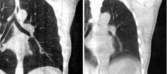
Fig. 14.1
Cone-beam CT images of the same patient using static cone-beam CT image reconstruction. Left Reconstruction from breath-hold acquisition of 95 projection images. Right Reconstruction from free-breathing acquisition of 670 projection images
14.2.2 Breathing Artifacts
Breathing motion impacts static cone-beam CT reconstruction because projection images are not consistent with static objects in the field-of-view. The backprojection of FDK algorithm (Eq. 14.2) implies that the impacted region encompasses every part of the field-of-view which superimposed on a part that moved during cone-beam acquisition in one or more projection images. The movement results in streaks tangential to the moving object in the X-ray directions which are typical of inconsistent or missing data. The periodicity of breathing motion tends to blur out the streaks near the moving parts, resulting in blurred moving objects, e.g., the diaphragm in Fig. 14.1.
The consequences of breathing artifacts in cone-beam CT for IGRT have not been fully investigated yet. In [17], the authors argue that blurred cone-beam CT images are generally sufficient for the localization of the tumor when registered on a corresponding reference image, e.g., the blurred 3D CT average computed from a conventional 4D CT. Another contradictory study [42] has obtained a significant difference between static and motion-corrected cone-beam CT with up to 5 mm difference on average between tumor localization with static and motion-corrected cone-beam CT. Moreover, improved image quality is beneficial for adaptive RT requiring (automatic) segmentation, deformable registration and dose accumulation. Anyhow, breathing artifacts were deemed preoccupying enough to trigger many investigations in the past few years on respiratory motion correction techniques for cone-beam CT. Two of them are described in the following: respiration-correlated cone-beam CT and motion-compensated cone-beam CT.
14.3 Respiration-Correlated Cone-Beam CT
Respiration-correlated cone-beam CT is very similar to conventional respiration-correlated CT described in Part I of the book. It is assumed that breathing motion is periodic, i.e., that the patient regularly recovers the same position during data acquisition. This periodicity is described with the phase or the amplitude of a respiratory signal which is typically one-dimensional. Respiration-correlated cone-beam CT consists in selecting projection images acquired at corresponding positions in the respiratory cycle using the respiratory signal. The selected subset of projection images is then used to reconstruct the 3D cone-beam CT image of the respiratory phase using a static reconstruction algorithm (Sect. 14.2.1). Repetition of the process at successive respiratory phases results in a 4D cone-beam CT image describing the respiratory motion of the patient over one respiratory cycle (see Sect. 14.5.1 for its estimation). Table. 14.1 provides an overview of the literature on respiration-correlated cone-beam CT.
Table 14.1
Overview of the literature on respiration-correlated cone-beam CT with scanners attached to the gantry of a linear accelerator
Author | Year | Respiratory signal | Reconstruction algorithm |
|---|---|---|---|
2005 | Processing of projection images (Fig. 14.2) | FDK | |
2006 | External radiopaque marker tracked in projection images | FDK | |
Purdie et al. [38] | 2006 | Processing of projection images | FDK |
Dietrich et al. [14] | 2006 | Abdominal belt | FDK |
2006 | Infrared external marker | FDK | |
Lu et al. [30] | 2007 | Infrared external marker | FDK |
2008 | Infrared external marker | FDK, MKB, PICCS | |
2008 | Infrared external marker | FDK for tomosynthesis | |
Rit et al. [43] | 2009 | Processing of projection images | FDK, SART |
2009 | Processing of projection images | FDK, AAPC, MKB, PICCS, ASD-POCS | |
2010 | Processing of projection images | FDK | |
Santoro et al. [49] | 2010 | Infrared external marker | FDK for tomosynthesis |
2011 | Infrared external marker | FDK, PICCS, MKB |
The respiratory signal is a key component of respiration-correlated cone-beam CT which varies between studies (Table. 14.1). As in conventional CT, external devices can be used to record a signal which must be synchronized with the acquisition, e.g., thoracic belts with a pressure sensor or surfacic infrared markers with a dedicated camera. However, cone-beam CT has an advantage over conventional CT: the full field-of-view  is covered by the X-ray beam at every projection image. Therefore, the whole sequence of projection images contains distinct motion information and it has been proposed to extract the respiratory signal from projection images. The advantage is that the signal is based on the motion of internal structures, it is perfectly synchronized with the projection images and no additional hardware is required.
is covered by the X-ray beam at every projection image. Therefore, the whole sequence of projection images contains distinct motion information and it has been proposed to extract the respiratory signal from projection images. The advantage is that the signal is based on the motion of internal structures, it is perfectly synchronized with the projection images and no additional hardware is required.Fig. 14.2
Example of algorithm for respiratory signal extraction from projection images, the Amsterdam shroud [54, 64]. Top Each projection image is processed with a derivative filter in the  direction and projected horizontally by taking the sum in the
  direction. Bottom The process is repeated for each projection and produces the columns of a 2D image from which the respiratory signal can be extracted
direction and projected horizontally by taking the sum in the direction. Bottom The process is repeated for each projection and produces the columns of a 2D image from which the respiratory signal can be extractedAmong the solutions for the extraction of the respiratory signal from the projection images, the Amsterdam shroud [44, 54, 64] is now used clinically for the on-the-fly reconstruction of 4D cone-beam CT images. The method consists in sequentially applying basic processing filters on each 2D cone-beam projection image to obtain the 2D image called the Amsterdam shroud by its authors. The axes of the Amsterdam shroud are the projection index horizontally, i.e. time, and the cranio-caudal position vertically (Fig. 14.2). This processing allows to highlight the moving structures which are perpendicular to the cranio-caudal axis, mainly the diaphragm domes. The respiratory signal is clearly visible in this image and it can be extracted with a simple correlation between consecutive columns.
The selection of a subset of projection images for static reconstruction poses a data sufficiency problem in respiration-correlated cone-beam CT. Without modification of the acquisition protocol or the reconstruction algorithm, large angular gaps between consecutive projection images of the selected subset produce streak artifacts. The problem lies in the relation between the length of the breathing cycle and the rotation speed, and the frame rate of the flat panel has little influence on this matter. Two solutions have been investigated to handle this problem. First, the angular gaps can be decreased by modifying the acquisition with a slower rotation [30, 34, 54] or multiple rotations [33]. Otherwise, several authors have attempted to develop specific reconstruction algorithms to reduce the amount of artifacts (Table 14.1). A comparative study has recently shown that image improvement must be cautiously analyzed for clinical use [2].
Fig. 14.3
Coronal (top) and axial (bottom) slices at the isocenter of, from left to right, the 3D cone-beam CT [15], the end-exhale and the end-inhale frame of the respiration-correlated 4D cone-beam CT [54] and the motion-compensated cone-beam CT [45]. The patient was a lung cancer patient treated with stereotactic body radiotherapy [53]. A sequence of 1318 projection images acquired over  in 4 min was used with an imaging dose of about 2 cGy. The average respiratory period of the patient during the acquisition was 3.5 s
in 4 min was used with an imaging dose of about 2 cGy. The average respiratory period of the patient during the acquisition was 3.5 sRespiration-correlated imaging enables the estimation of breathing motion during treatment fractions of lung [52, 53] and upper-abdominal targets [7, 8]. The first clinical system for 4D cone-beam CT recommended a gantry rotation speed four times slower than regular 3D cone-beam CT and a dose per projection divided by four to maintain the same total dose per cone-beam acquisition [54]. These settings were a trade-off between acquisition time and image quality (Fig. 14.3). The increase in acquisition time, the decrease in image quality and the residual motion artifacts due to the incorrectness of the periodicity assumption have pushed for the development of motion compensation techniques.
14.4 Motion-Compensated Cone-Beam CT
Motion-compensated cone-beam CT is the domain of tomography which aims at finding the dynamic tomography  from the sequence of projection images
  using an estimate of the deformation of the objects in the field-of-view during acquisition. There are two challenges in motion-compensated CT reconstruction: (1) to estimate the deformation during the cone-beam acquisition and (2) to incorporate the estimate in the reconstruction. Table 14.2 provides an overview of the state-of-the-art on motion-compensated cone-beam CT for IGRT. The problem of motion estimation is described in the next section. This section briefly summarizes the different solutions to the reconstruction problem assuming a known motion estimate.


from the sequence of projection images using an estimate of the deformation of the objects in the field-of-view during acquisition. There are two challenges in motion-compensated CT reconstruction: (1) to estimate the deformation during the cone-beam acquisition and (2) to incorporate the estimate in the reconstruction. Table 14.2 provides an overview of the state-of-the-art on motion-compensated cone-beam CT for IGRT. The problem of motion estimation is described in the next section. This section briefly summarizes the different solutions to the reconstruction problem assuming a known motion estimate.Table 14.2
Overview of the literature on motion-compensated cone-beam CT with scanners attached to the gantry of a linear accelerator
< div class='tao-gold-member'>
Only gold members can continue reading. Log In or Register to continue
Stay updated, free articles. Join our Telegram channel
Full access? Get Clinical Tree
